
Renault Midlum Truck Wiring Diagrams Manual 2017 – Complete Electrical Schematics PDF
Original price was: $52.95.$34.95Current price is: $34.95.
Full Renault Midlum wiring diagrams manual, document 70203-06, dated 1/2017. Covers DXi4 variants with complete electrical schematics, CAN bus architecture, fuse and relay tables, connector pinouts, and equipment locations for professional diagnostics and repair.
Description
Renault Midlum Wiring Diagrams Manual – 2017 Edition
This is the complete wiring diagrams manual for Renault Midlum trucks, document number 70203-06, published January 2017. It contains the full electrical schematics, connector pinouts, fuse and relay tables, and component location diagrams needed to diagnose, repair and maintain the electrical systems on Midlum DXi4 variants. Every diagram is referenced to a sheet number and equipment code, so you can trace circuits from the power source through to the component without guesswork.
File Details
- Manual Type: Wiring Diagrams / Electrical Schematics Manual
- Brand: Renault Trucks
- Model: Midlum
- Document Number: 70203-06
- Edition: 1/2017
- Language: English (multilingual information notices included)
- Page Count: 300
- File Format: PDF
Chapters Covered
- Communication BUS Architecture
- Equipment Keys
- Summary of Diagrams
- Energy Production (Without and With ADR Equipment)
- ADR Control ECU
- Electrical Distribution (1/6 through 6/6)
- Vehicle Electronic Management (1/2 and 2/2)
- Main Information Display
- Tachograph
- FMS On-Board Management
- FMS + RAL On-Board Management
- OPTIFLEET Onboard Management
- Engine Electronic Management (1/2 and 2/2)
- Managing the Urea Supply
- Differential Lock
- 6AS800/6AS1000 Gearbox
- ALLISON 3000V Gearbox
- S2000 Gearbox
- Electrical Retarder
- EBS Braking System
- Air Suspension (Rear Electronic, Full Electronic)
- Air Production Management
- Door/Immobiliser Management
- Alarm
- Lighting and Signalling Management (1/3 through 3/3)
- Front Electric Windows, Sun-Roof
- Adjustable Heated Door Mirrors
- Comfort Accessories
- Radio
- AT 2000ST Independent Heating
- AT2000ST Independent Heating (ADR)
- Air Conditioning
- Body Builder Pre-Equipment Management
- Available Power Supplies (1/2 and 2/2)
- Trailer Connectors
- Diagnostic Socket
- CAN Bus Transfer Zones (J1587-1, J1939-1, J1939-2, J1939-ENG)
- Equipment Locations
- Fuse Tables
- Relay Tables
- Connectors
Communication BUS Architecture
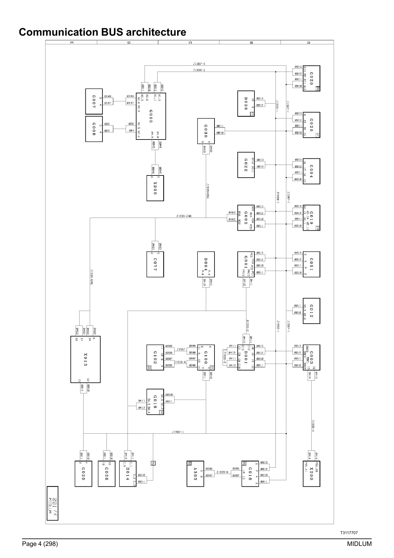
Opens with the network topology for the vehicle’s communication systems, showing how the ECUs, displays and control units interconnect across the CAN bus segments. Includes connector references and the J1587-1, J1939-1, J1939-2 and J1939-ENG bus transfer zones that link the vehicle management, engine management, body builder and diagnostic systems.
Electrical Distribution
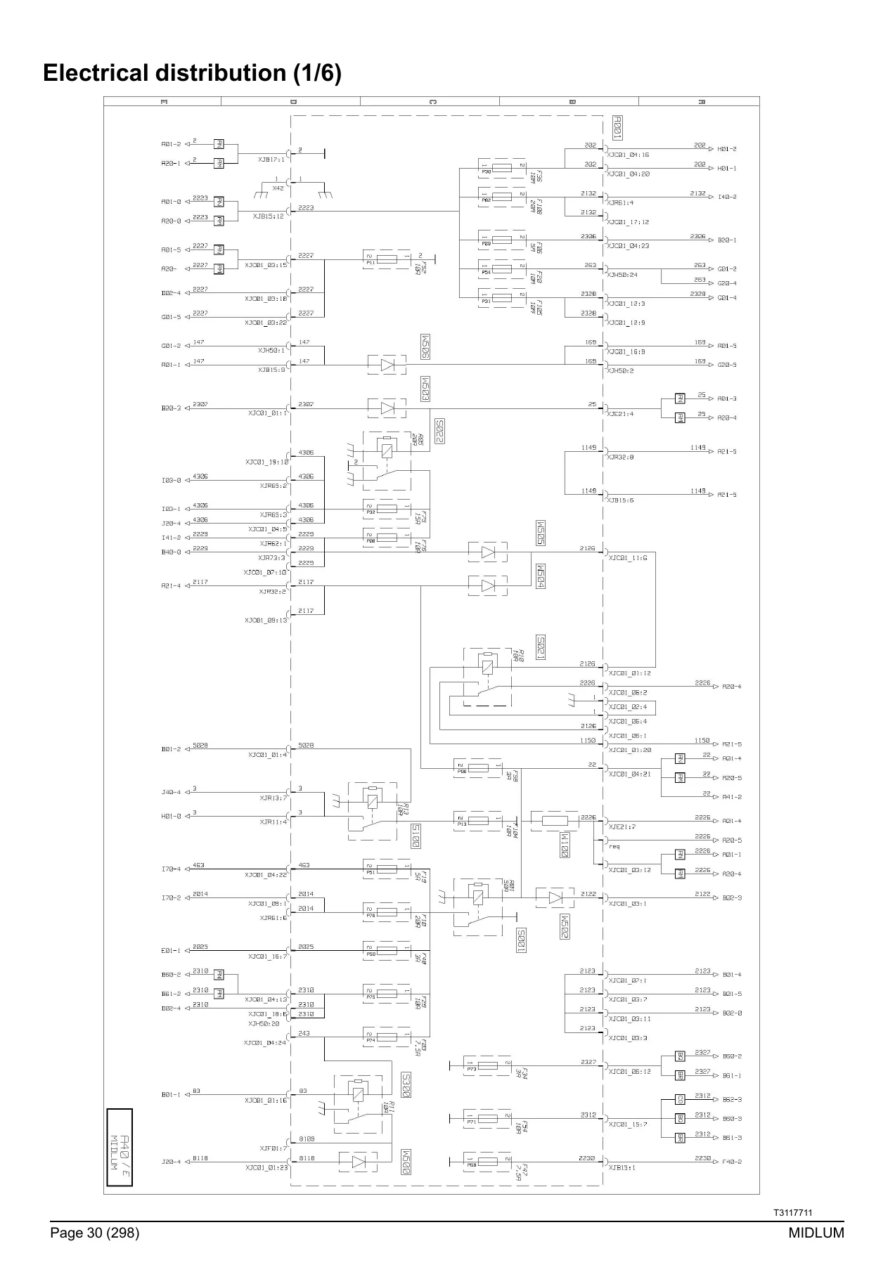
Six detailed sheets covering the fuse and relay distribution throughout the cab, from battery feed through master switch, ignition and accessory circuits. Each sheet shows the power supply relays, fuse ratings, and the circuits they protect, including after-ignition supplies, lighting circuits, and body builder feeds.
Vehicle and Engine Electronic Management
Circuit diagrams for the vehicle management control unit, engine management ECU, throttle pedal sensors, cruise control, PTO controls and the interaction between the VECU and EECU. Also covers the main information display, tachograph, and on-board management systems including FMS, FMS+RAL and OPTIFLEET.
Engine and Emission Systems
Diagrams for the DXi 5 and DXi 7 engine electronic management, including sensors, injectors, engine brake solenoid valves, air preheating and boost pressure control. The urea supply management chapter covers the pump module, heating resistors, metering solenoid valve and nitrogen oxide concentration sensor.
Transmission, Braking and Suspension
Covers the 6AS800/6AS1000 automated manual gearbox, ALLISON 3000V and S2000 automatic gearboxes, electrical retarder, EBS braking system with ABS/EBS trailer socket, and the air suspension variants for 4×2 and 4×4 configurations, including rear electronic and full electronic systems.
Cab and Body Systems
Door and immobiliser management, alarm system, lighting and signalling management across three sheets, front electric windows and sun-roof, adjustable heated door mirrors, comfort accessories, radio, independent heating and air conditioning.
Body Builder and Available Power Supplies
Body builder pre-equipment management with PTO controls, plus comprehensive tables of available power supplies for auxiliary equipment — including after master switch, after ignition, engine speed signals, PTO controls and lighting supplies. Also covers trailer connectors, diagnostic socket and all earth points.
Fuse, Relay and Connector Reference
Complete fuse tables for the electrical distribution box and for fuses outside the box, relay tables with ratings and circuit assignments, and connector pinout tables for the dashboard harness, chassis-cab connection and trailer sockets.
Equipment Locations
Photographic and diagrammatic location guides for components throughout the vehicle — dashboard controls, engine bay sensors, urea supply components, EBS modulators, air suspension valves, gearbox ECUs, and body builder connectors. Each location is cross-referenced to the relevant diagram sheet.
Why This Manual Matters
Electrical faults on commercial vehicles are rarely solved by guesswork. This manual gives you the actual circuit paths, connector pinouts and component locations for the Renault Midlum DXi4 range. Whether you are troubleshooting a CAN bus communication error, replacing a sensor, installing body builder equipment, or tracing a short in the lighting circuit, the correct diagram saves hours of diagnostic time and prevents damage to expensive ECUs.
What You Can Do With It
- Trace circuits from battery to component using sheet references and equipment codes
- Identify fuse and relay assignments for every circuit in the cab and chassis
- Diagnose CAN bus faults using the network topology and bus transfer zone diagrams
- Locate sensors, actuators and ECUs using the equipment location chapters
- Wire auxiliary equipment correctly using the available power supply tables
- Read connector pinouts for the dashboard harness, chassis-cab interface and trailer sockets
- Understand the interaction between VECU, EECU, EBS, air suspension and body builder systems
IMAGES PREVIEW
Instant PDF Delivery
This Renault Midlum wiring diagrams manual is delivered as a PDF download immediately after purchase — no shipping, no waiting. You can view it on any device, print individual sheets for the workshop, and keep the complete manual on hand for every diagnostic session. The 2017 edition covers the DXi4 variants listed in the coverage table, giving you a current and accurate reference for the electrical systems on these trucks.
Reviews
There are no reviews yet.