Rohde Schwarz FSQ26 Signal Spectrum Analyzer Service Manual Repair Guide PDF
Original price was: $85.00.$21.95Current price is: $21.95.
Complete factory service manual for Rohde & Schwarz FSQ Signal Analyzer series including FSQ3, FSQ8, FSQ26, FSQ31, and FSQ40 models. Professional technical documentation covering performance testing, adjustment procedures, module replacement, troubleshooting, and firmware updates for these precision RF spectrum analyzers (10 MHz to 40 GHz frequency range). Includes detailed circuit diagrams, calibration procedures, spare parts lists, and comprehensive repair instructions for RF/microwave test equipment technicians and service engineers.
Description
Rohde Schwarz FSQ26 Signal Spectrum Analyzer Service Manual Repair Guide PDF DOWNLOAD
DESCRIPTION
This official Rohde & Schwarz FSQ Service Manual provides comprehensive technical documentation for the complete FSQ Signal Analyzer series, covering installation, performance verification, calibration, troubleshooting, and repair of these professional-grade RF/microwave spectrum analyzers. This extensive 279-page manual is essential for test equipment technicians, metrology engineers, and service professionals maintaining precision measurement instruments in laboratories, production facilities, and calibration centers.
Instrument Overview
The Rohde & Schwarz FSQ Signal Analyzer series represents professional-grade RF and microwave spectrum analysis equipment designed for demanding test and measurement applications. These precision instruments combine exceptional frequency coverage, dynamic range, and measurement accuracy for applications in telecommunications, aerospace, defense, broadcast, and electronics manufacturing.
FSQ Series Model Coverage:
R&S FSQ3 (Order No. 1155.5001.03)
- Frequency Range: 10 MHz to 3.6 GHz
- Applications: General RF testing, wireless communications
R&S FSQ8 (Order No. 1155.5001.08)
- Frequency Range: 10 MHz to 8 GHz
- Applications: Extended RF coverage, microwave testing
R&S FSQ26 (Order No. 1155.5001.26)
- Frequency Range: 10 MHz to 26.5 GHz
- Applications: Microwave communications, satellite systems
R&S FSQ31 (Order No. 1155.5001.31)
- Frequency Range: 10 MHz to 31 GHz
- Applications: Advanced microwave testing (tested as FSQ40 with frequency limit)
R&S FSQ40 (Order No. 1155.5001.40)
- Frequency Range: 10 MHz to 40 GHz
- Applications: Millimeter-wave testing, advanced radar systems
Key System Features
Advanced Measurement Capabilities:
- Wide frequency coverage from 10 MHz to 40 GHz (model-dependent)
- High dynamic range for sensitive measurements
- Low phase noise performance for precision analysis
- FFT bandwidth options for time-domain analysis
- I/Q baseband input capability (Option B71)
- I/Q bandwidth extension (Option B72)
- External mixer support for extended frequency range (Option B21)
RF Performance Features:
- Electronic attenuator (Option B25) for extended dynamic range
- Preamplifier (Option B25) for improved sensitivity
- RF attenuator with precision step control
- Frequency counter accuracy < 1×10⁻⁹
- Third-order intercept optimization
- Harmonic distortion measurement
- IF image frequency rejection
- Display linearity verification
Modular Architecture:
- Frontend module for RF signal processing
- Synthesizer board (A110) for frequency generation
- IF filter module (A130) for selectivity
- Detector board (A120) for signal detection
- Microwave converter units (A160) for frequency conversion
- Front module controller (A90) for user interface
Available Options
Option FSQ-B4 / FSP-B4:
- OCXO (Oven-Controlled Crystal Oscillator)
- Enhanced frequency stability
- Improved reference accuracy
Option FSQ-B10 / FSP-B10:
- External generator control interface
- Automated test system integration
Option FSU-B9:
- Tracking generator functionality
- Amplitude modulation capability
- Frequency modulation
- I/Q modulation support
Option FSU-B20:
- Flash disk storage expansion
Option FSU-B21:
- External mixer capability
Option FSU-B23:
- Additional measurement functions
Option FSQ-B25:
- Electronic attenuator for extended dynamic range
- Preamplifier for improved sensitivity (26.5 GHz)
Option FSQ-B71:
- I/Q baseband input
- Demodulation analysis
Option FSQ-B72:
- I/Q bandwidth extension
- Enhanced time-domain analysis
Comprehensive Manual Contents
CHAPTER 1: PERFORMANCE TEST
Complete verification procedures for all specifications:
Basic Performance Tests:
- IF Image Frequency Rejection – Verifies image suppression
- IF Rejection – Confirms intermediate frequency rejection
- Nonlinearities – Tests third-order intercept performance
- Harmonic Distortion – Measures harmonic content
- FFT Bandwidth – Verifies time-domain analysis accuracy
- Level Accuracy Bandwidth Switching – Tests level accuracy across bandwidth changes
- Bandwidth verification and shape factor measurement
- Noise Display – Background noise level verification
- Frequency Response – Flatness across frequency range
- Level Accuracy – Absolute amplitude measurement accuracy
- Display Linearity – Ensures accurate visual representation
- RF Attenuator – Step accuracy verification
- IF Gain Switching – Confirms proper gain transitions
- Reference Level Switching – Validates reference level changes
- Phase Noise – Measures local oscillator phase noise performance
Option B25 Tests (Electronic Attenuator/Preamplifier):
- Noise Display with Preamplifier
- Level Accuracy with Preamplifier
- Frequency Response with Preamplifier
- Level Accuracy with Electronic Attenuator
- Frequency Response with Electronic Attenuator
- Nonlinearities with Electronic Attenuator
- Third-Order Intercept with Electronic Attenuator
- RF Attenuator verification with B25
- Electronic Attenuator standalone test
Option B9 Tests (Tracking Generator):
- TG Output Level verification
- TG Frequency Response flatness
- TG Amplitude Modulation accuracy
- TG-I/Q Modulation performance
- TG Frequency Modulation linearity
Option B71 Tests (I/Q Baseband Input):
- I/Q compensation frequency response
- Baseband input characteristics
- Demodulation accuracy
Option B72 Tests (I/Q Bandwidth Extension):
- Extended bandwidth verification
- Time-domain analysis performance
Option B21 Tests (External Mixing):
- External mixer interface verification
- Extended frequency range testing
Detailed Test Equipment Requirements: All tests include specific required equipment:
- Frequency counter (Advantest R5361B with Option 23)
- Signal generators (R&S SMP03/04, SMHU)
- Power meters and sensors (Agilent 11667B, Anritsu K240C, RNA)
- 50-Ohm terminations and attenuators
- Phase noise test equipment
- Calibration standards
Performance Test Reports:
- Complete FSQ performance test report forms (pages 1.73-1.97)
- Option FSQ-B71 test report (pages 1.98+)
- Option FSQ-B25 test report (pages 1.87+)
- Option FSU-B9 test report (pages 1.84+)
CHAPTER 2: ADJUSTMENT
Comprehensive calibration and adjustment procedures:
Manual Adjustment Procedures:
- Password Access – Service mode entry (page 2.2)
- Reference Frequency Adjustment – OCXO calibration
- Calibration Signal Level – Internal reference adjustment
- Level Accuracy Adjustment – Multi-point amplitude calibration
- Frequency Accuracy Adjustment – Frequency reference correction
- Power Reference Adjustment – Power measurement calibration
Automatic Adjustment Functions:
- Module Data Adjustment – Automated calibration after module replacement
- Frequency Response Correction – Flatness compensation
- Required measuring equipment and accessories listed
- Step-by-step adjustment sequences
CHAPTER 3: REPAIR
Detailed troubleshooting and module replacement:
Function Description:
- Block Diagram Analysis (pages 5.5, 5.21)
- Instrument Design overview
- Component interaction explanation
Module Function Descriptions:
RF Section:
- Electronic Attenuator (Option B25)
- Function description (page 3.2)
- Replacement procedure (page 3.73)
- RF Attenuator (A40)
- Function explanation (page 3.2)
- Replacement instructions (page 3.36)
- Preamplifier (Option B25)
- Operation principles (page 3.2)
- Service procedures
Frontend & Signal Path:
- RF Frontend module
- Function details (page 3.3)
- Replacement procedure (page 3.40)
- Microwave Converter Unit (A160)
- Operation principles (page 3.4)
- Replacement instructions (pages 3.45, 3.51)
- IF Filter (A130)
- Selectivity function (page 3.5)
- Replacement procedure (page 3.44)
- Detector Board (A120)
- Signal detection principles (page 3.6)
- Replacement instructions (page 3.43)
Synthesizer & Reference:
- Synthesizer (A110)
- Frequency generation (page 3.41)
- Replacement procedure
- OCXO (Option FSQ-B4)
- Frequency reference (page 3.8)
- Replacement instructions (page 3.63)
- Calibration Signal generator
- Internal reference (page 3.8)
User Interface:
- Front Panel components (page 3.9)
- Keyboard replacement (page 3.24)
- LC Display (LCD)
- Function (page 3.9)
- Replacement (page 3.22)
- Front Module Controller (A90)
- Interface control (page 3.9)
- Replacement (page 3.15)
- Key/Probe Board (A80)
- Function (page 3.10)
- Replacement (page 3.38)
- Vol/Phone Board (A191)
- Audio interface (page 3.38)
System Components:
- Motherboard (A10)
- System control (page 3.10)
- Replacement (page 3.33)
- Power Supply unit
- Function (page 3.10)
- Replacement (page 3.28)
- DC/AC Converter
- Replacement (page 3.22)
- Fan cooling system
- Replacement (page 3.29)
Storage & Interface:
- Hard Disk drive
- Replacement (page 3.20)
- Floppy Disk Drive
- Replacement (page 3.27)
- Flash Disk (page 3.11)
- External Mixer interface (page 3.11)
- External Generator Control (FSQ-B10)
- Replacement (page 3.65)
Connectors & Hardware:
- RF INPUT Connector
- Cable W1 replacement (page 3.30)
- Connector replacement (page 3.31)
- RF-INPUT module (page 3.32)
- Lithium Battery
- Replacement procedure (page 3.17)
- Front Cover removal (page 3.26)
- Switching Membrane (page 3.24)
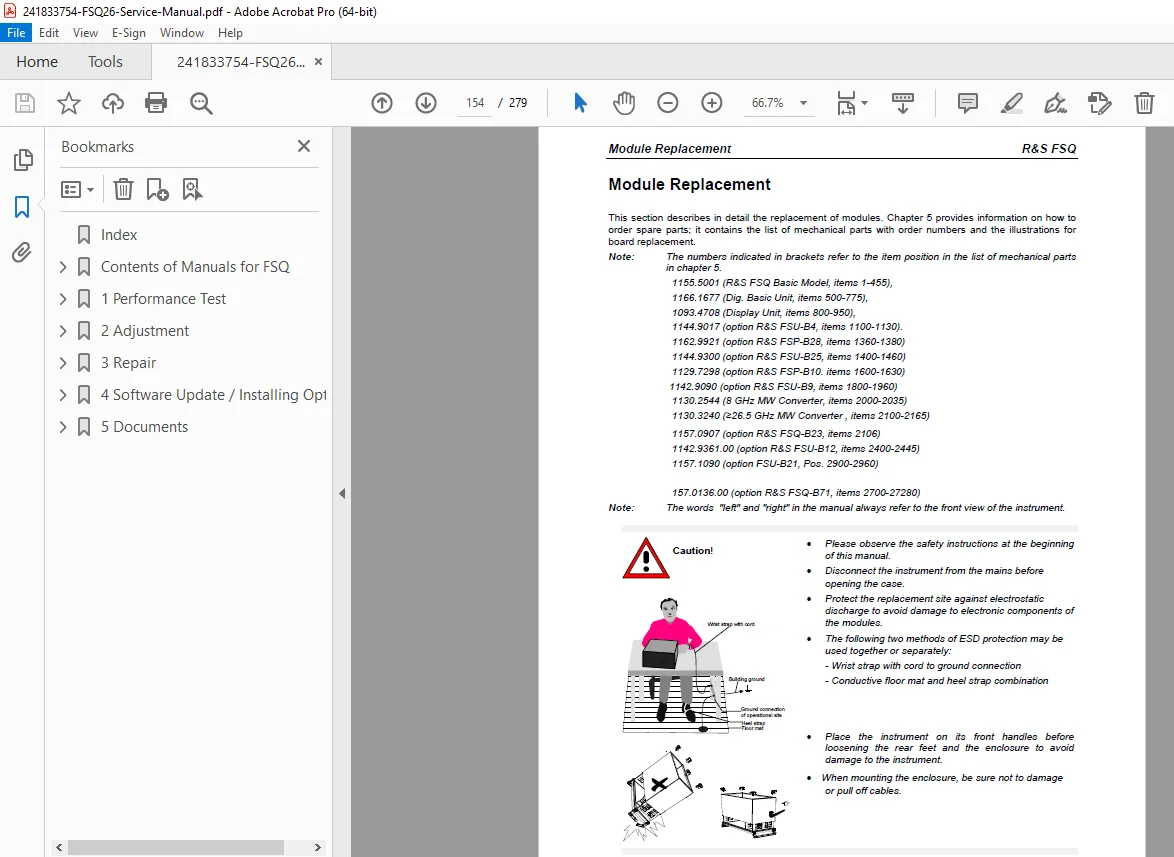
Module Overview & Replacement:
- Complete module layout diagram (page 3.14)
- General replacement procedures (page 3.12)
- Required tools and precautions
Troubleshooting Procedures:
- Boot Problems diagnostics (page 3.77)
- Switch-on Problems (page 3.76)
- RF Converter troubleshooting (page 3.102)
- Error Messages:
- “DETECTOR access failed!” (page 3.82)
- “LOUNL” error (page 3.102)
- Systematic fault isolation
- Test equipment requirements (page 3.75)
CHAPTER 4: FIRMWARE UPDATE / INSTALLATION OF OPTIONS
Software and hardware expansion:
Firmware Update Procedures:
- Update process overview (page 4.1)
- Software installation steps
- Version compatibility
Option Installation:
- Complete option list (page 4.3)
- FSU-B9 tracking generator installation (page 4.3)
- Hardware option retrofitting procedures
- Software option activation
- Post-installation verification
CHAPTER 5: DOCUMENTS (ANNEX)
Complete technical documentation:
Circuit Documentation:
- Block Circuit Diagrams (pages 5.5, 5.21)
- Detailed system architecture
- Signal flow illustrations
- Component interconnections
Mechanical Documentation:
- Mechanical Drawings (page 5.5)
- Physical dimensions
- Mounting specifications
- Connector locations
Spare Parts Information:
- Complete Spare Parts List (page 5.7)
- Part numbers and descriptions
- Ordering Procedures (page 5.2)
- Refurbished Modules availability (page 5.2)
- Express service information
Electrical Documentation:
- Power Cables specifications (page 5.3)
- Wiring diagrams
- Connection schematics
Required Test Equipment
This manual specifies precision test equipment for verification:
Frequency Reference:
- Advantest R5361B Frequency Counter with Option 23
- Accuracy requirement: < 1×10⁻⁹
- Frequency range: up to 10 MHz
Signal Sources:
- R&S SMP03 (1035.5005.03) – for FSQ40 testing
- R&S SMP04 (1035.5005.04) – 1 MHz to 3.6 GHz
- R&S SMHU (0835.8011.52) – Low phase noise source
- Phase noise @ 640 MHz: < -100 dBc/Hz @ 100 Hz
- Phase noise: < -115 dBc/Hz @ 1 kHz
- Phase noise: < -127 dBc/Hz @ 10 kHz
Power Measurement:
- Agilent 11667B Power Splitter
- Anritsu K240C Power Sensor
- RNA Power Meter
Terminations & Attenuators:
- Precision 50-Ohm terminations
- Calibrated attenuators for various frequency ranges
Safety and Compliance
Safety Requirements:
- Equipment returned for repair must use original or ESD-protective packing
- Safety tests mandatory after component replacement
- Visual inspection, PE conductor test, insulation resistance, leakage current measurement
- Functional testing required
- Connections must comply with IEC 950 / EN 60950
- Lithium battery handling precautions
- Proper battery disposal procedures (environmental-friendly recycling)
- Battery must not be exposed to high temperatures or fire
- Only use specified R&S replacement batteries
Quality Assurance:
- Certificate of Quality included
- R&S® registered trademark of Rohde & Schwarz GmbH & Co. KG
- Manufactured in Federal Republic of Germany
- Spare Parts Express Service available
Support Resources
Technical Support:
- List of R&S representatives worldwide
- Service and repair contact information
- Spare parts ordering procedures
- Express service availability
Who Should Use This Manual?
- RF/Microwave test equipment technicians
- Calibration laboratory engineers
- Metrology specialists
- Electronics production test engineers
- Telecommunications equipment technicians
- Aerospace/defense test engineers
- Broadcast engineering staff
- Research laboratory technical staff
- Rohde & Schwarz authorized service centers
Manual Features
✓ Official Rohde & Schwarz factory service manual
✓ 279 pages of comprehensive technical documentation
✓ 5 complete chapters plus technical annex
✓ Multi-model coverage (FSQ3, FSQ8, FSQ26, FSQ31, FSQ40)
✓ Detailed performance test procedures with equipment lists
✓ Step-by-step adjustment protocols
✓ Module-level repair instructions
✓ Complete circuit diagrams and block diagrams
✓ Mechanical drawings and dimensional data
✓ Comprehensive spare parts lists
✓ Troubleshooting flowcharts
✓ Option installation procedures
✓ Firmware update instructions
✓ Test report templates included
This service manual provides test equipment technicians with complete factory-level technical knowledge for maintaining, calibrating, and repairing Rohde & Schwarz FSQ Signal Analyzer series instruments to original manufacturer specifications.
FILE DETAILS
Manual Name: Rohde & Schwarz FSQ Signal Analyzer Service Manual
Models Covered: R&S FSQ3, FSQ8, FSQ26, FSQ31, FSQ40
Year: 2005 (Updated May 2005)
Manual Quality: Excellent – Clear text, detailed diagrams, professional formatting
Number of Pages: 279 pages
File Format: PDF
File Size: 2.3 MB
Language: English
Publication Number: 1155.5047.82-05-1
Publisher: Rohde & Schwarz GmbH & Co. KG, Test and Measurement Division
Country of Origin: Federal Republic of Germany