
Rolls-Royce Aquapilot AzT US 105 FP Control System Service Manual – Work No. 514-P829
Original price was: $44.95.$26.95Current price is: $26.95.
Complete Rolls-Royce Aquapilot Control System Service Manual for the AzT US 105 FP azimuth thruster. Covers steering, propeller RPM control, CANMAN processes, alarms, tuning, wiring and part lists. Work No. 514-P829, serials 65863-65865.
Description
Rolls-Royce Aquapilot AzT US 105 FP Control System Service Manual
This is the full Aquapilot Control System Service Manual for the Rolls-Royce AzT US 105 FP azimuth thruster, issued under Work No. 514-P829 and covering serial numbers 65863, 65864 and 65865. It is the ND (New Design) document set from Rolls-Royce Oy Ab in Rauma, Finland, and it is the reference volume for maintaining, adjusting, tuning, troubleshooting and repairing the complete Aquapilot control chain – from the bridge control head and panel down to the azimuth thruster control unit in the thruster room. The manual runs to 337 pages of service data, wiring information, block diagrams and part lists, and is written in English.
File Details
- Manual type: Service Manual (ND document)
- Brand / manufacturer: Rolls-Royce Oy Ab, Rauma, Finland
- Model: AzT US 105 FP (Aquapilot Control System)
- Work No.: 514-P829
- Serial Nos. covered: 65863, 65864, 65865
- Revision: A, dated 06.06.2011 – New ND document
- Language: English
- Page count: 337 pages
- File format: PDF
Chapters Covered
The manual is organised into 22 top-level sections, each with its own sub-sections and drawing references. The chapter list below reflects the manual’s own structure:
- 1. General Information – contents of the Aquapilot Service Manual, general rules, terminology, warnings and cautions, safety information, disposal and scrapping, spare parts ordering, global support network
- 2. Control System Data – general electrical specifications
- 3. Maintenance, Check Lists – general maintenance instructions, maintenance programme for the control system, maintenance programme for the Aquapilot control lever
- 4. Settings and Adjustings – Hand Held Terminal (HHT), tuning instruction, AZT thrust angle feedback and zero angle setting
- 5. Alarms and Trouble Shooting – list of alarm points, serial link I/O unit alarm indications, descriptions of alarm points
- 6. Aquapilot Control System Description – Aquapilot for AZT with FPP and clutch HyTu
- 7. Aquapilot Steering
- 8. Secondary Steering
- 9. Control Head Lever Synchronizing – Aquapilot ND lever synchronization
- 10. Propeller RPM Control
- 11. Maintenance Control System – maintenance control switch
- 12. Thrust Direction and RPM Indication – thrust direction and speed indication, operation description for FPP, configuration switches and figures
- 13. CANMAN Processes – TURNCONT, THRUST, COMMAND, CS_MODE_4, AQP2, SLIO, LT_D_5, SPECIAL, PANELS2, LOGICS, CLUTCH and SUPERVIS (ACU11/ACU12/ACU13) process block diagrams
- 14. Azimuth Thruster Control Unit – ACU dimensions, assembly, wiring
- 15. Bridge Interface Unit – BIU dimensions, assembly, wiring
- 16. AZT and Hydraulic Instrumentation – transmitter boxes, instrument cables, sin-cos potentiometers
- 17. Control Voltage Power Supply – DC main supply, AC power supply, battery change-over
- 18. Interface to Other Control Systems – autopilot interface, DP system interface, functional description
- 19. General Arrangement and Dimension Drawings – control system GA, Aquapilot control head, TDI-11 and TDI-12, ACP, BCP, CanOpen connections, power supply units
- 20. Installation, Storage – electric installations, storage instructions, storing of the Aquamaster propulsion unit, electric motors
- 21. Interconnection Diagrams – cabling instructions, cable list, overview diagram, bus cables, control cables, data cables, alarm cables, power cables
- 22. Part Lists
What this adds up to for a working technician is a single-source control system reference. The Aquapilot AzT US 105 FP is a digital follow-up (FU) steering and RPM control system built around a CANOpen fieldbus, with the main CCN02 application processor sitting inside the Azimuth Thruster Control Unit (ACU) and communicating with the bridge through Bridge Interface Units (BIU) over a CAN Slio bus. This manual explains that architecture end-to-end and then hands you the practical material needed to service it: process block diagrams for every CANMAN application, calibration routines for the analogue and digital I/O, tuning tables for steering speed, thrust and dimmer curves, alarm descriptions with operation capability and recovery steps, mechanical zero-angle setting procedures for the azimuth feedback transmitters, and the full interconnection and cable reference so you can trace a fault from the bridge lever to the valve coil in the thruster room.
What You Can Do With This Manual
The Aquapilot control system is not a simple electrical panel – it is a distributed network of levers, panels, interface units, controllers, sensors and hydraulically actuated steering gear, and faults can sit anywhere along that chain. This manual gives you the diagnostic and adjustment material to work that chain methodically:
- Set and calibrate steering feedback – mechanical azimuth zero-angle alignment at the transmitter box, plus the electrical zero-point setting routines for the ATC feedback transmitter B3, the digital TDI-11 thrust direction transmitter B4 and the analogue TDI-A1 sin-cos transmitter B14, all performed at terminal strip X2.
- Tune the Aquapilot loop – unlinearity correction tables for the control lever, RPM request tables, asymmetric steering tables, dimmer correction tables and the follow-up turning speed tables (PWM-CWMIN, PWM-CCWMIN, PWM-CWMAX, PWM-CCWMAX) for AZT1, AZT2 and AZT3.
- Configure nodes and buses – panel bus IDs and Aquapilot bus IDs via DIP switches and rotary switches, CAN bus bit rates, SLIO bus bit rates and node names through the Hand Held Terminal.
- Calibrate I/O with the HHT – analogue input and output channel calibration, digital channel polarity, numeric calibration of channels, simulation and watching of internal process signals, and table editing for function curves and ramp delays.
- Diagnose and clear alarms – every alarm point is listed with where it lives, what the unit can still do while the alarm is active, and how to get off the alarm, covering SLIO failures, steering and pitch sensor failures, command failures, supply voltage faults, AQP thrust and steering faults, panel faults, bus A/B failures, clutch and lubrication pressure/temperature alarms and hydraulic pump faults.
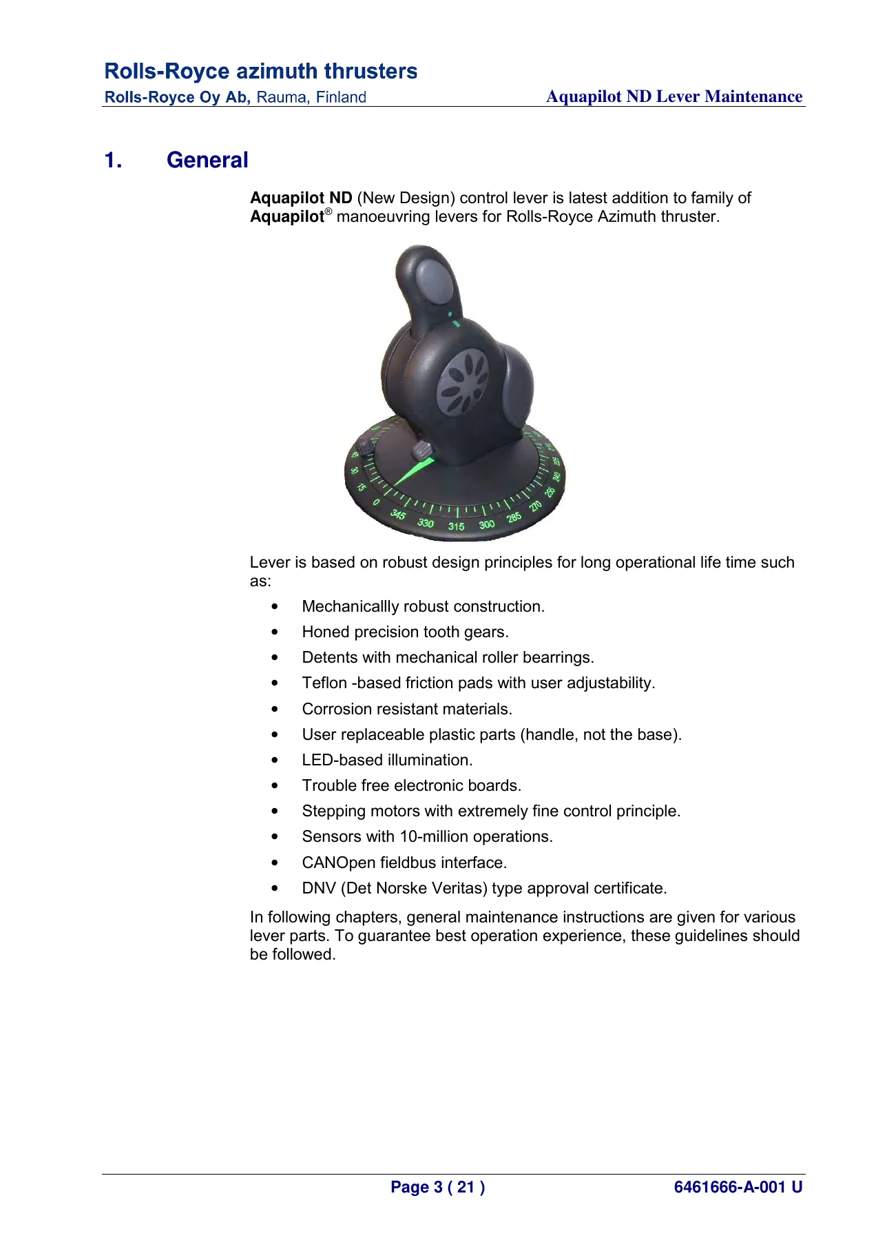
- Service the Aquapilot ND lever – removal of the lever housing, internal lubrication with MOLYDUVAL AERO 92 grease, replacement of the inner scale ring, replacement of the thrust grip, and a maintenance responsibility chart with spare part codes.
- Understand and service the TDI – configuration switch settings, encoder type selection, dimmer selection, RPM display and thrust bar scaling, RPM scaling rotary switches, error codes and connection terminal assignments.
- Work the interfaces – autopilot 4-20 mA angle reference, DP system handshake and 4-20 mA set value, azimuth feedback signals, and the interlocking conditions that must be met before a thruster is ready for DP or autopilot control.
- Wire and install – cabling instructions with classification society requirements, cable tag decoding, gland sizes, voltage drop calculation for 24 VDC circuits, power cable current tables and cable lists for every bus, control, data, alarm and power cable in the system.
Why This Manual Matters
Aquapilot azimuth thruster control systems are tuned, calibrated and configured – not simply repaired. A steering feedback transmitter set a few degrees off, an RPM table left at the wrong breakpoint, or a follow-up lever that has not been recalibrated after a control station change-over can all produce handling behaviour that looks like a hardware failure but is actually a setup problem. Working without the correct procedure wastes time, risks damaging sensors during calibration, and can leave a vessel operating with degraded control margins. This manual supplies the actual values, terminal numbers, table breakpoints and step-by-step procedures rather than generic advice, so adjustments stay within the tolerances the system was designed for.
IMAGES PREVIEW
Instant Delivery
The Rolls-Royce Aquapilot AzT US 105 FP Control System Service Manual is delivered as an instant PDF download – no shipping, no waiting, no physical book to lose in the engine room. Read it on a laptop at the control desk, on a tablet in the thruster room, or print the specific diagrams and tables you need for the job in front of you. Once purchased, the file is yours to keep and reference whenever the vessel needs attention.
Reviews
There are no reviews yet.