
Rolls-Royce MW 200 H / CU 81 U3 High Pressure Hydraulic Deck Machinery Use and Maintenance Manual – PDF
Original price was: $39.95.$23.95Current price is: $23.95.
Complete use and maintenance manual for the Rolls-Royce MW 200 H / CU 81 U3 high pressure hydraulic deck machinery – combined mooring winches and cable lifter units built for DSME newbuildings H5289 and H5290. Covers mechanical, hydraulic, installation, commissioning, adjustment and operating instructions.
Description
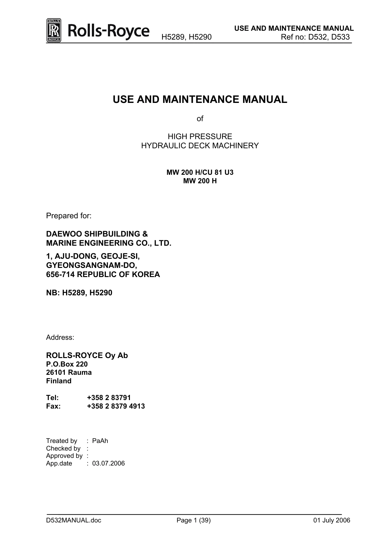
The Rolls-Royce MW 200 H/CU 81 U3 High Pressure Hydraulic Deck Machinery Use and Maintenance Manual is the full documentation package prepared by Rolls-Royce Oy Ab, Rauma, for Daewoo Shipbuilding & Marine Engineering Co., Ltd. It covers the combined hydraulic anchor/mooring winch and cable lifter units installed on newbuildings H5289 and H5290, together with the separate hydraulic mooring winches of the same MW 200 H family. Everything a superintendent, chief engineer or deck machinery technician needs to install, commission, adjust, operate, maintain and troubleshoot these winches is contained in this one document.
File Details
- Manual type: Use and Maintenance Manual (high pressure hydraulic deck machinery)
- Brand / supplier: Rolls-Royce Oy Ab, Rauma, Finland (Rauma Winches / Rauma Brattvaag)
- Equipment: MW 200 H/CU 81 U3 combined mooring winch / cable lifter unit and MW 200 H hydraulic mooring winches
- Prepared for: Daewoo Shipbuilding & Marine Engineering Co., Ltd., Geoje-si, Republic of Korea
- Newbuilding numbers: H5289, H5290
- Technical specification no.: 50048-05
- Work no.: 514-D532
- Language: English
- Page count: 162 pages
- File format: PDF
- Approval date shown: 03.07.2006
Chapters Covered
- General – technical specification 50048-05, painting scheme and pretreatment of steel surfaces, spare part list, instructions for ordering spare parts, service representatives
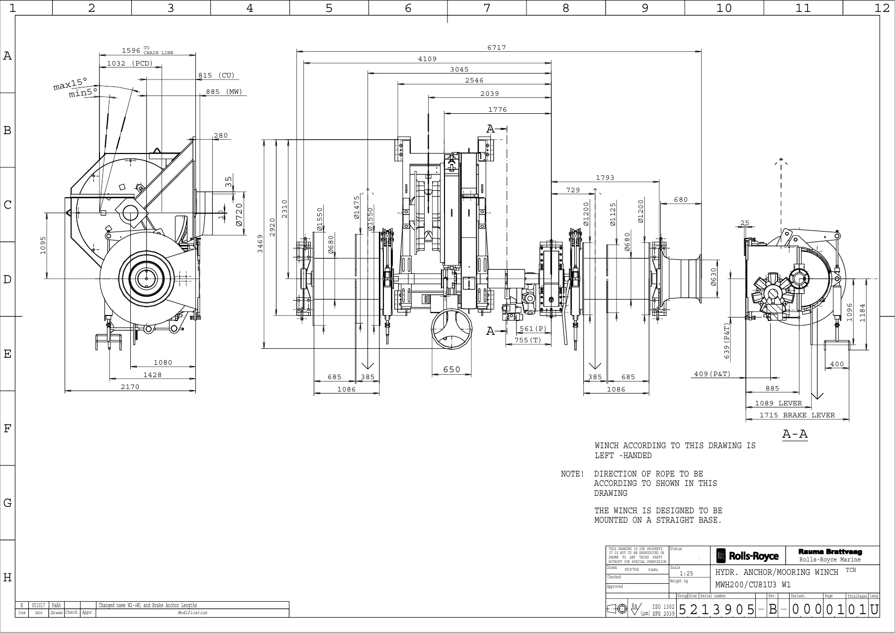
- Dimensional drawings – general arrangement, hydraulic anchor/mooring winch W1 and W2 footprints, hydraulic mooring winches M1, M2, M3, M4 and M5 with footprints, bell mouth, remote control stands fore/aft and mid, brake test kit
- Assembly drawings and part lists – cable lifter unit assembly left handed and right handed, brake assembly CU, claw clutch assembly CU, claw clutch assembly MW, pinion line assembly, mooring assemblies 7K and 11KK and M4/M5, gear case assembly left handed and right handed, brake assembly MW
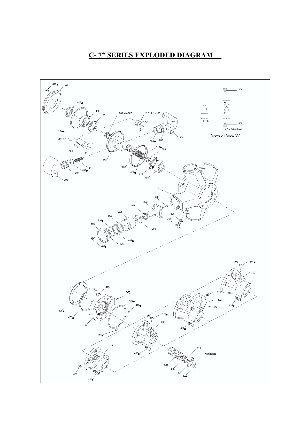
- Hydraulic drawings – hydraulic assembly drawings for W1/W2 and the mooring winches, hydraulic schemes, winch valve 32P–F324, winch valve bolt torque instructions, SAE flange pressure line, SAE flange return line, check valve H9, ball valve H8, pressure reducing valve H5, shuttle valve H6, spare part drawing of HMC270 motor and pages for HMC hydraulic motor
- Mechanical instructions – storage instructions for electric and hydraulic instruments, installation and start-up of deck machinery, winch foundations, anchoring plates and brake band support, bell mouth, welding, protective bars, start-up of winches, recommended lubricants, oil quality and change instruction, maintenance and trouble shooting for the mechanical part of winches
- Hydraulic instructions – installation and commissioning of hydraulic equipment, cleaning and flushing of pipes, pressure test, oil filling, starting of electric motors, bleeding, adjustment of system, flushing of hydraulic pipes, flushing report example, commissioning checklist, recommendations for hydraulic oils, adjustment instructions for winch valve and local control valve, maintenance intervals at 50 hours, 12 weeks and 52 weeks, service instruction for the Oldham coupling, service instruction for rotation change of the hydraulic motor
- Mechanical instruction drawings – main shaft line alignment, anchoring plate mounting for CU and MW, assembly of brake support and chain stripper, CU brake adjusting, MW brake adjusting, checking brake lining wear, rope end fastening on drum, removing brake lining, fastening brake lining, lubrication instruction for mooring winch and CU, lifting instructions for mooring winch and cable lifter
- Instructions for use – cable lifter unit operation including lowering the anchor by motor, dropping the anchor with the manually operated band brake and with the band brake hydraulics, heaving the anchor, and hydraulic mooring winch operation including local control, operation with drum, operation with warping end, speed range selector, start-up in cold conditions and action in case of black-out
Read as a whole, the document is not simply a set of parts lists. It walks through the entire life of the equipment: how the units are lifted and stored before installation, how the deck foundations are levelled and how the anchoring plates for the band brakes are positioned and welded so the brakes actually open correctly, how the hydraulic piping is flushed and pressure tested, how the winch valve is set and the pressure relief values adjusted, and finally how the winches are driven in normal service – locally from the winch control valve or remotely from the control stands on both ship sides. The brake chapter is unusually detailed: it explains in plain terms what happens to brake band clearance, lining wear and even speed control when the brake anchor plate is welded in the wrong place, which is one of the most common installation faults on this type of machinery.
Equipment and Systems Covered
The manual documents the combined mooring winch / cable lifter unit MW 200 H/CU 81 U3 with one cable lifter, two mooring drums and one warping end, and the MW 200 H mooring winches with two or three mooring drums plus warping end. Cable lifter duties, mooring drum duties and warping end duties are given separately, along with the oil supply each unit needs from the central power unit and the working pressure in the operating line. On the hydraulic side the document covers the winch valve assembly, the pressure reducing valve, shuttle valve, check valve and ball valve, the SAE flange connections for pressure and return lines, and the HMC hydraulic motor including its exploded views, parts identification, performance data and fault diagnosis tables.
Mechanical coverage includes the open reduction gear of the windlass with its steel cover, the closed oil bath / splash lubricated gear case of the mooring winch, brake bands, brake linings, brake pins, claw clutches, pinion line, main shaft line alignment, mooring and warping end assemblies, and the slide bearings in the rope drums and cable wheels. The lubrication schematics list every grease nipple position, the quantity of lubricant, and whether the interval is 4 weeks / 8 operating hours or 2 weeks / 4 operating hours, so nothing has to be guessed at during routine greasing.
Why This Manual Matters on Board
Deck machinery of this class is unforgiving. A band brake that has been set up against a badly positioned anchoring plate will drag, overheat and wear linings far faster than designed, and on the cable lifter it will also make speed control difficult when the anchor is being lowered. A claw clutch that opens under load because the foundation was not levelled within tolerance can put a mooring line or an anchor cable into free run. The instructions in this manual are written to prevent exactly those situations – levelling limits, stopper plate installation, clutch alignment, brake support adjustment, flushing cleanliness targets and pressure settings are all stated with the figures required rather than left to judgement.
For the hydraulic side, the commissioning sequence is given step by step: cleaning and flushing of pipes, the filtration grade and cleanliness class that must be reached before flushing can be stopped, oil filling through the return filter, momentary starting of electric motors to confirm rotation, and bleeding at the lowest possible pressure with the claw clutches disconnected. Adjustment of the winch valve covers both the mooring winch and the combined mooring winch / cable lifter version, so the pressure relief valve and the automatic speed range selection valves can be set correctly for each duty.
Troubleshooting is handled in two places. The mechanical section lists the symptoms a crew actually reports – unusual running sound from the gearing, abnormal vibration of the winch, oil leakage from the gear case, a band brake that will not hold, a band brake that drags or shakes, a connecting clutch that opens when the winch is loaded, metal swarf coming out of a slide bearing – with the checks and remedies for each. The hydraulic motor section adds a separate fault diagnosis table covering a motor that will not run, a motor running in the wrong direction, a fall in motor speed, shaft seal leakage, oil leakage and abnormal noise.
Above all, this is a working document rather than a brochure. It includes the actual installation instruction drawings for main shaft line alignment, anchoring plate mounting, brake support and chain stripper assembly, brake adjusting, brake lining wear limits, rope end fastening on the drum, brake lining removal and refitting, lubrication schematics and lifting instructions for both the mooring winch and the cable lifter. The operating chapter then ties it together with the procedures used day to day: lowering the anchor by motor, dropping the anchor on the manually operated band brake or on the band brake hydraulics, heaving the anchor, hauling and paying out on the mooring drum, working the warping end, choosing the speed range, warming the winches in cold conditions and what to do in a black-out.
If you are responsible for the installation, commissioning, survey, maintenance or safe operation of these Rolls-Royce / Rauma hydraulic deck machinery units, this manual gives you the procedures and the numbers in one place instead of scattered across drawings and separate instruction sheets.
Get the Complete Rolls-Royce MW 200 H/CU 81 U3 Manual
With this manual on hand you can set up the winch foundations and stopper plates correctly, position and weld the brake anchoring plates so the band brakes open evenly, adjust the brake support and lining clearance to specification, flush and pressure test the hydraulic piping to the cleanliness class required, fill and bleed the system, set the winch valve pressure relief and two-speed changeover values, carry out the 50-hour, 12-week and 52-week maintenance routines, replace brake linings with the correct bonding and riveting method, and diagnose the faults that stop a winch working. Correct procedures and the right specifications are what keep these units holding load and lasting between surveys.
IMAGES PREVIEW
Delivery is instant – the moment your order is complete you can download the PDF and open it on a laptop, tablet or phone at the winch, in the engine room or in the office. Print the pages you need for the job in hand and keep the rest on file. No shipping, no waiting, no paperwork.
Reviews
There are no reviews yet.