
Rolls-Royce MW 315 HA / CU 122 U3 Hydraulic Deck Machinery Use and Maintenance Manual – Mooring Winches, Cable Lifters & Power Packs
Original price was: $67.95.$44.95Current price is: $44.95.
Complete Rolls-Royce use and maintenance manual for the MW 315 HA / CU 122 U3 hydraulic deck machinery package — mooring winches W1–W2 and M1–M10, cable lifters, HP3-3×131 power packs, hydraulic schematics, electrical drawings, and full maintenance procedures. 229-page PDF.
Description
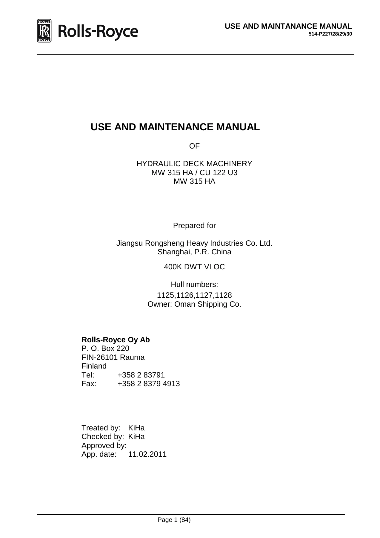
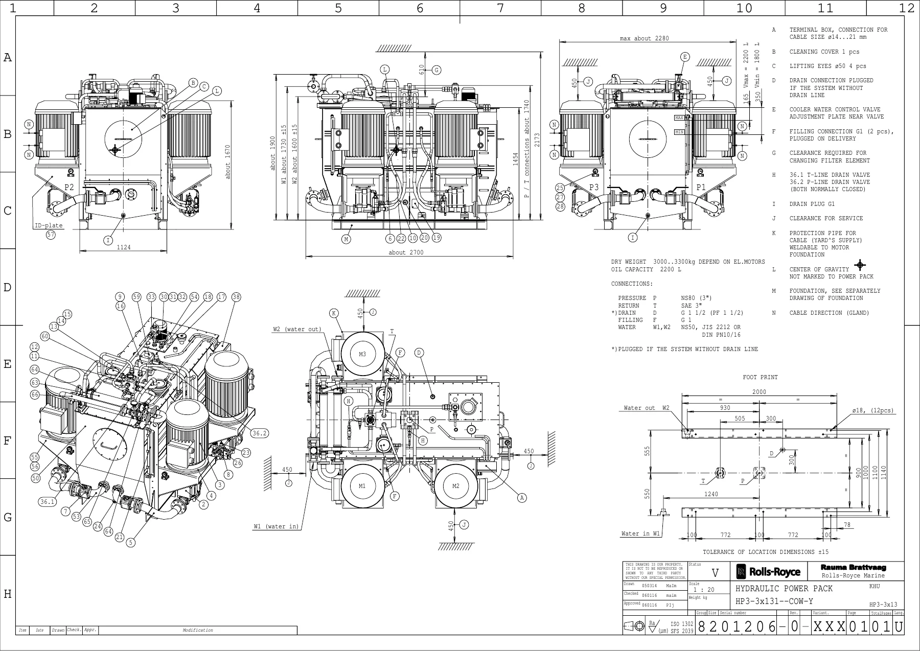
This is the complete Use and Maintenance Manual for the Rolls-Royce MW 315 HA / CU 122 U3 hydraulic deck machinery package supplied for the 400K DWT VLOC newbuildings constructed at Jiangsu Rongsheng Heavy Industries Co. Ltd. (Shanghai, P.R. China) for Oman Shipping Co. The manual covers the combined mooring winch/cable lifter units W1–W2 (type MW315HA/CU122U3), the ten mooring winches M1–M10 (type MW315HA), the forward and aft hydraulic power packs (type HP3-3×131), the NP12 chain stoppers, the RCS12 remote control stands, and all associated hydraulic, electrical and mechanical systems. Whether you are commissioning a new installation, troubleshooting a hydraulic fault, adjusting brake bands, or ordering spare parts, this manual provides the procedures, diagrams, and specifications you need.
File Details
- Manual type: Use and Maintenance Manual
- Brand: Rolls-Royce (Rolls-Royce Oy Ab, Rauma, Finland)
- Primary model: MW 315 HA / CU 122 U3
- Equipment type: Hydraulic deck machinery — mooring winches and cable lifters
- Work number: 514-P227-28-29-30
- Technical specification: 90792-03
- Date: 11.02.2011
- Language: English
- Page count: 229 (PDF file pages)
- File format: PDF
- Prepared for: Jiangsu Rongsheng Heavy Industries Co. Ltd., Shanghai, P.R. China
- Vessel: 400K DWT VLOC — Hull numbers 1125, 1126, 1127, 1128; Owner: Oman Shipping Co.
Chapters Covered
The manual opens with a warnings and cautions page that must be read before any work is attempted, then proceeds through spare parts, technical specifications, and the full set of mechanical, hydraulic, and electrical drawings before detailing installation, operation, maintenance, and troubleshooting.
- 1. General Statement: Warnings and Cautions
- 2. General / Spare Parts
- 3. Technical Specification
- 4. Mechanical Dimension and Foundation Drawings
- 5. Hydraulic Drawings
- 6. Electric Drawings
- 7. General & Mechanical Instructions
- 8. Instructions on the Hydraulic Equipment
- 9. Electric Instructions
- 10. Mechanical Instruction Drawings
- 11. Mechanical Assembly/Component Drawings
- 12. Instructions for Use
- 13. Maintenance and Trouble Shooting
Safety, Installation and Commissioning (Chapters 1 & 7)
Chapter 1 sets out the safety responsibilities and warnings that apply to all work covered by the manual. Chapter 7 provides detailed storage instructions for electric and hydraulic instruments — covering storage place, air quality, temperature limits, means of storage, and lifting. It then walks through installation and start-up of the deck machinery: lifting procedures, storage and protection before start-up, winch foundations and levelling requirements, anchoring plates and brake band support (including specific procedures for the CU cable lifter and MW mooring winch), bell mouth installation, welding precautions, protective bars, and the start-up sequence for winches. Lubricant recommendations and oil quality/change instructions are also included, along with a trouble-shooting guide for the mechanical part of the winches.
Hydraulic Equipment (Chapter 8)
This is the core technical section for the hydraulic system. It covers pipe material selection, cutting, laying, cleaning, painting, and pressure testing, plus pump unit installation, pipe flushing, oil filling, motor starting, bleeding, and system adjustment. The flushing procedure is detailed with flow rates, oil temperature targets, filtration grades (10 µm or better), and ISO 4406 cleanliness targets (class 18/13). Hydraulic oil recommendations are given for three climate groups (variable winter conditions, variable conditions, and tropical), with viscosity grade, viscosity index, pour point, and maximum operating temperature for each. Adjustment instructions for the HP3 power pack are provided, including pressure compensator and relief valve setting procedures. Maintenance intervals are laid out for the first 50 hours, routine checks, 12-week and 52-week service intervals. A dedicated section covers the tube oil cooler — installation, start-up, operation, cleaning and inspection intervals, mechanical and chemical cleaning of the tube side, and step-by-step assembling/disassembling procedures with O-ring replacement guidance. The chapter closes with trouble shooting for the oil cooler.
Electric Equipment (Chapter 9)
Installation instructions for electric equipment cover installation and fitting inspections, switching on the supply, connections (with warnings about thermistors and heatsinks), electroconductive bolt fittings and clamping moments, groundings, heating, protection during building onboard ship, and readjustments. Cabling instructions cover supply and motor cables, control and heating circuits (<250 VAC), and instrumentation/measuring circuits (<24 VDC). Cable and motor insulation checks are detailed for motor cables, mains cables, and motor windings. Installation instructions for the electric motor cover transport, ventilation, condensation drain, transmission elements, alignment (angular and parallel), electrical connection, insulation resistance, direction of rotation, and Y/D starting. Maintenance instructions cover cleaning, bearings (including regreasing schedules by frame size and speed), bearing seals, dismantling, and assembly. A faults table maps mechanical and electrical symptoms to possible causes. Repair instructions and spare parts guidance are also included.
Mechanical Drawings and Assemblies (Chapters 4, 5, 10, 11)
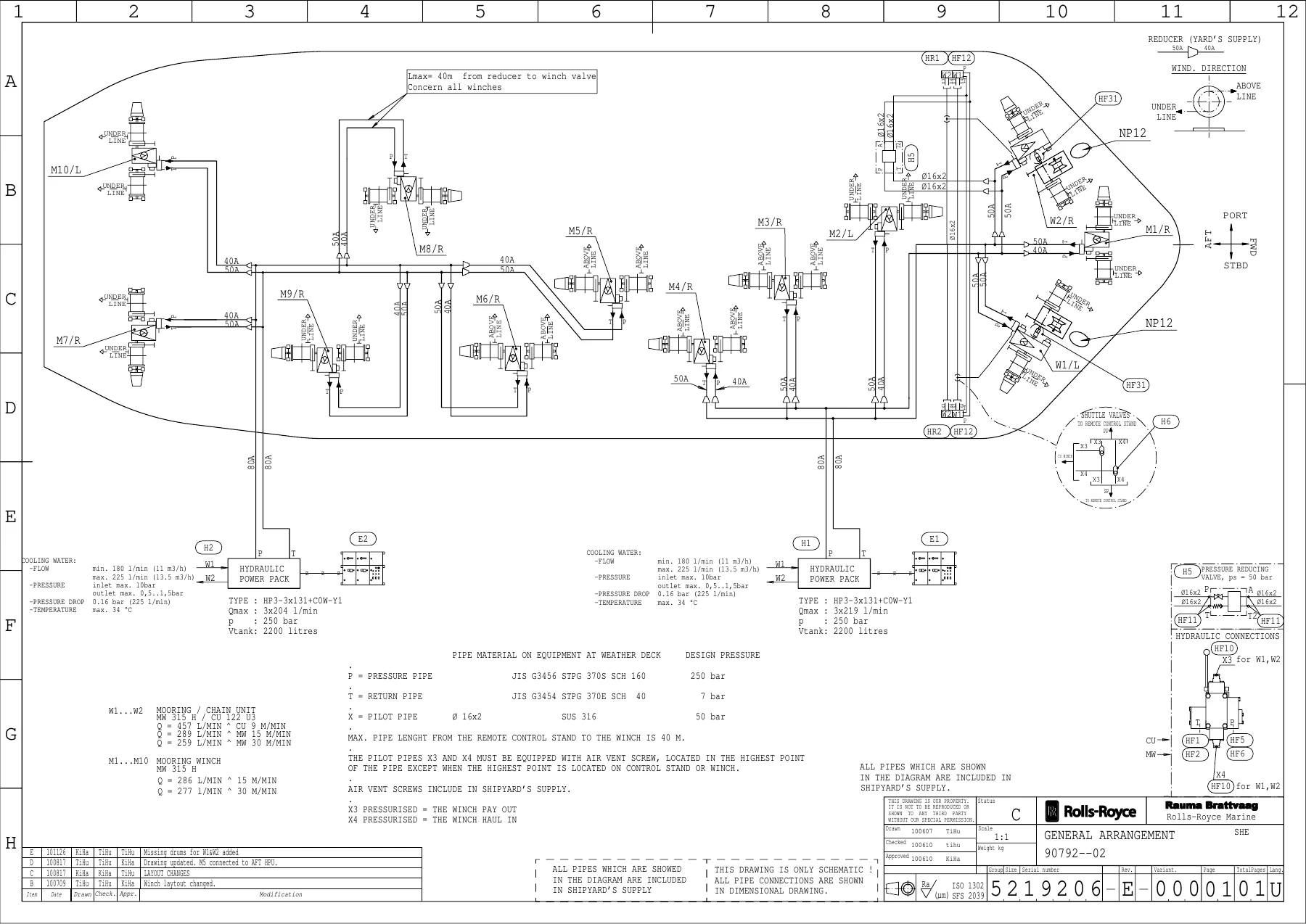
The manual contains an extensive set of engineering drawings. Chapter 4 provides mechanical dimension and foundation drawings for each winch variant (W1, W2, M1 through M10), bell mouth, chain stopper, and additional jack bolt instructions for the windlasses. Chapter 5 covers hydraulic drawings including the general arrangement (5219206), welding flanges for JIS pipes, hydraulic assemblies for W1/W2 and M1/M2, hydraulic diagrams for auto-tension winches, power pack hydraulic diagrams, oil cooler drawings, remote control stand, shuttle valve, pressure reducing valve, hose assembly, and assembly drawings for the direction valve, return block, base block, two-speed valve, and pressure block. Chapter 10 lists mechanical instruction drawings for main shaft line alignment, anchoring plate mounting, brake support and chain stripper assembly, brake adjusting, rope end fastening, brake lining wear checking/removal/fastening, and lubrication schemas. Chapter 11 contains the mechanical assembly/component drawings for the cable lifter unit, cable lifter brake, pinion line, claw clutch, mooring assembly, gear case (left- and right-handed), mooring winch brake, and mooring winch claw clutch — each with part lists.
Instructions for Use (Chapter 12)
Chapter 12 provides operating procedures for the cable lifter unit (lowering the anchor by motor, dropping the anchor with the manually operated band brake, dropping with the band brake hydraulics, and heaving the anchor), the hydraulic auto-tension mooring winch (local and remote control, operation with drum and warping end, mooring auto-tension, speed range selector, start-up in cold conditions, and in case of black-out), and the hydraulic power pack (starting and stopping).
Maintenance and Trouble Shooting (Chapter 13)
The final chapter consolidates maintenance instructions for the mechanical part, bolt fittings to be checked by torque spanner, trouble shooting for the mechanical part of winches, maintenance instructions for hydraulic equipment (first 50 hours, routine, 12-week, 52-week), oil cooler maintenance, trouble shooting for the oil cooler, and electric motor maintenance.
What This Manual Enables You To Do
With this manual on hand you can commission the Rolls-Royce MW 315 HA / CU 122 U3 deck machinery package from scratch — level foundations, align shafts, install brake anchoring plates correctly, flush hydraulic pipes to ISO cleanliness targets, fill and bleed the system, and adjust the power pack pressure compensators and relief valves. You can operate the cable lifter and mooring winches safely, including the auto-tension mode, and you can diagnose and repair faults across the mechanical, hydraulic, and electrical systems. The manual’s detailed parts lists and exploded drawings let you identify and order the correct spare parts, while the maintenance schedules keep your equipment within specification.
The value of having the correct procedures and specifications cannot be overstated on equipment of this class. A brake anchoring plate welded in the wrong position can destroy brake linings and impair speed control; hydraulic pipes flushed to an inadequate cleanliness level can fail pumps and motors; incorrect bolt torque can lead to leaks or structural failure. This manual gives you the manufacturer’s own numbers and methods, not guesswork.
IMAGES PREVIEW
Your manual is delivered as an instant PDF download — no shipping, no waiting. Access it on any device: laptop, tablet, or smartphone. Print the pages you need for the workshop or deck, and keep the full manual on file for future reference. Whether you are a marine engineer, deck officer, shipyard technician, or fleet maintenance manager, this manual is an essential reference for the Rolls-Royce MW 315 HA / CU 122 U3 hydraulic deck machinery.
Reviews
There are no reviews yet.