
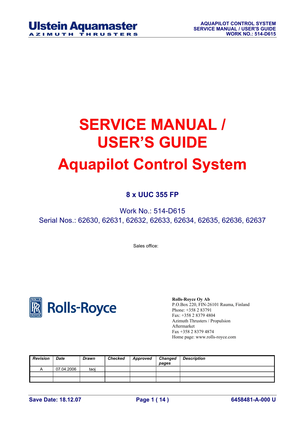
Rolls-Royce Ulstein Aquapilot UUC355 FP Service Manual and User Guide – 514-D615
Original price was: $34.95.$19.95Current price is: $19.95.
Complete Rolls-Royce Ulstein Aquapilot UUC355 FP service manual and user guide for Work No. 514-D615, covering Aquamaster azimuth thruster control systems across eight units (AQM1-AQM8). Includes tuning instructions, alarm descriptions, wiring diagrams, interconnection diagrams and full part lists.
Description
Rolls-Royce Ulstein Aquapilot UUC355 FP Service Manual and User Guide
This Rolls-Royce Ulstein Aquapilot UUC355 FP Service Manual and User Guide is the technical documentation set issued for Work No. 514-D615, covering the Aquapilot control system installed across eight Aquamaster azimuth thruster units. The manual is written for the service engineer, commissioning technician and vessel technical superintendent who needs the reference material behind the Aquapilot steering, thrust and alarm functions on these thrusters.
Everything inside this Aquapilot UUC355 FP service manual is built around the delivered configuration: eight thruster nodes (AQM1 through AQM8), their individual Aquamaster Control Units (ACU11-ACU18), the Bridge Control Units (BCU9029.01 and BCU9029.02), the wheelhouse panels (ACP01O, ACP02O, ACP03O), the Aquapilot control heads and the Thrust Direction Indicators. The setting, tuning and calibration procedures in this Aquapilot service manual are presented unit by unit, so the technician can work directly on the node in front of them rather than interpreting a generic description.
File Details
- Manual type: Service Manual and User Guide
- Brand: Rolls-Royce / Ulstein Aquamaster
- System: Aquapilot Control System – UUC 355 FP
- Work No.: 514-D615
- Serial Nos.: 62630, 62631, 62632, 62633, 62634, 62635, 62636, 62637
- Language: English
- Format: PDF
- Revision code visible: 6458481-A-000 U (index pages)
Chapters Covered
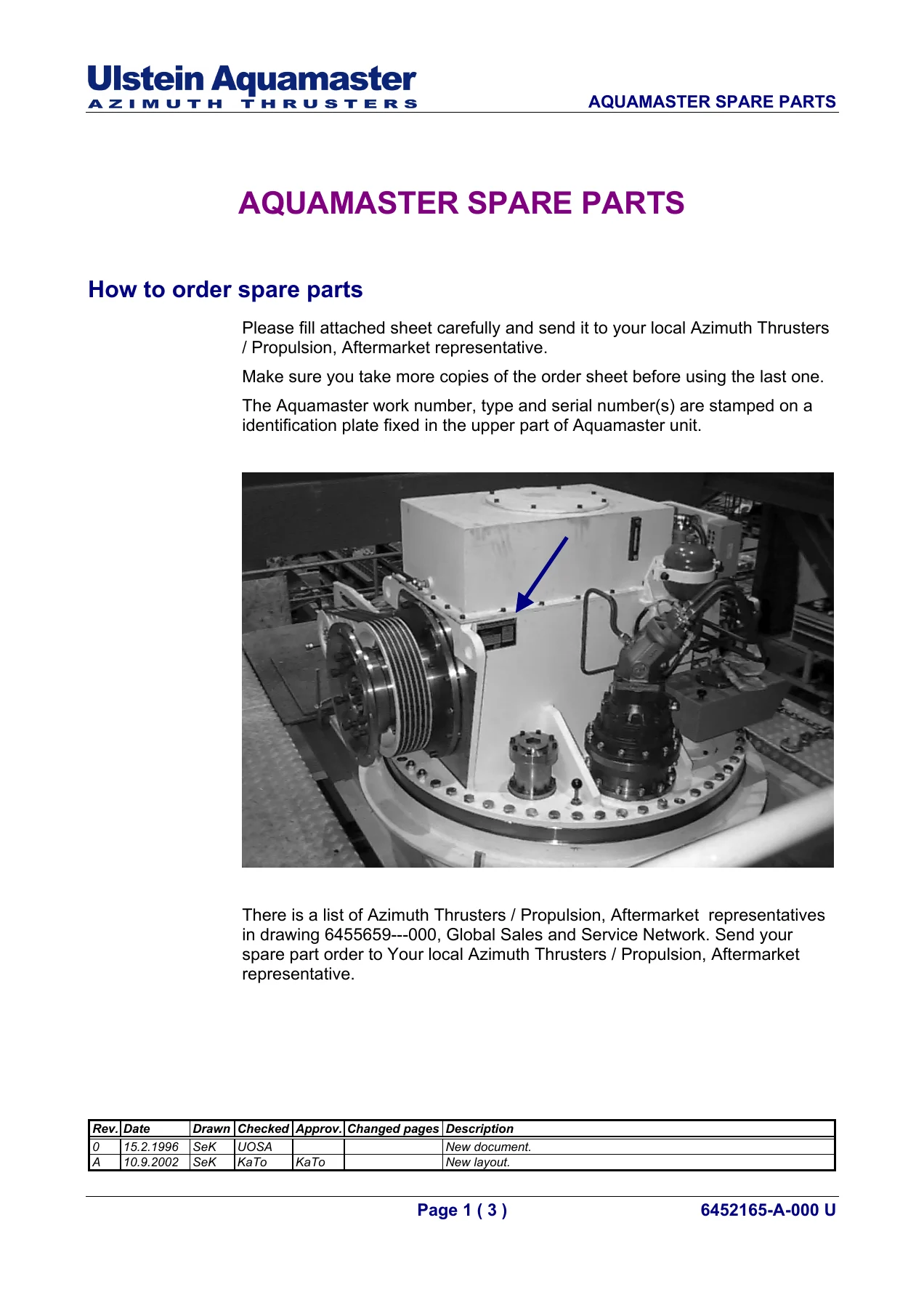
- 1. General Information – Contents of the Aquapilot service manual, general rules, terminology, warnings and cautions, safety information, electrical specifications, product disposal and scrapping, ordering spare parts, global support network
- 2. Maintenance, Check Lists – General instructions for maintenance, maintenance programme for control system
- 3. Settings and Adjustings – Hand Held Terminal (HHT), tuning instructions, Aquamaster thrust angle setting for TDI, Aquamaster thrust angle setting for feedback
- 4. Alarm and Failure Indications – Serial link I/O unit alarm indications, description of alarms, I/O list, failure history via HHT terminal, FMEA worksheet
- 5. Control Devices – Aquamaster control panels ACP01O and ACP01OD, ACP02O, ACP03O, Aquamaster steering by Aquapilot, thrust power control by Aquapilot, feeling point of the Aquapilot control lever, thrust direction and speed indication, local turning and RPM control, draining pump control
- 6. Interface to Other Control Systems – Sin-cos potentiometer for azimuth feedback, interlocking signals
- 7. CANMAN Applications, ACU – Command, feedback, turn control, thrust, CCO, alarm applications AQM1 through AQM8
- 8. CANMAN Applications, BCU – Supervis applications AQM1 through AQM8, AQP, panels, logical, command
- 9. Aquamaster and Hydraulic Instrumentation – Hydraulic unit X8, lubrication unit X9, expansion tank X5, shaft brake XB1 and XB2, gravity tank X108, draining pump unit, transmitter box X2, connection boxes
- 10. GA / Dimension / Assembly / Wiring Diagrams – General arrangement, ACU dimension and assembly drawings, BCU9029.01 and BCU9029.02 drawings and circuit diagrams, ACP drawings and wiring diagrams, Aquapilot control head dimension, assembly and wiring diagrams, HHT interface panel, TDI dimension drawing, maintenance controller, draining pump starter, cables with connector
- 11. Installation, Storage – Electric installations, storage instructions, storing of Aquamaster propulsion unit, electric motors
- 12. Interconnection Diagrams – Overview diagram, control cables, plug connector cables, power cables, alarm cables, bus cables, data cables for thrust direction control and indicators, data cables for HHT, cabling instructions
- 13. Part List – Full bill of materials and part lists for the UUC 355 delivery
Taken as a whole, this Aquapilot UUC355 FP service manual gives the technician a complete working picture of the control chain – from the wheelhouse control head and bridge panels, through the CAN bus, into the ACU and out to the steering gear, hydraulic unit and feedback transmitters. The settings and tuning chapters are the practical core, and the wiring, interconnection and part list sections back them up with the drawings needed when a cable, board or potentiometer has to be identified or replaced.
What This Rolls-Royce Aquapilot Service Manual Enables You to Do
With this Aquapilot UUC355 FP service manual in hand, a trained technician can carry out the full commissioning and calibration sequence for each of the eight thruster nodes. That includes zero-offset and linearity correction of the Aquapilot control head, setting of the clutch engage and disengage values, the RPM request curve, and the dimmer adjustment table for each BCU. It also covers the ACU-side tuning: engine room control enable, RPM request curve, local control turning values, steering feedback setting, and the remote control turning valve parameters with their minimum and maximum command values.
The alarm and failure chapters let you work through the diagnostic path in a structured way. You can read the serial link I/O status LEDs, look up alarm and interlock descriptions by tag, and use the Hand Held Terminal to pull up the last fifty system messages to establish a failure history. The FMEA worksheet and I/O list support that work with the underlying signal-level detail.
Because this document is a service manual and user guide combined, it also serves as the operating reference for the Aquapilot control head – steering direction control, thrust power control through the vertical lever tilt, the feeling point of the lever, and the local turning and RPM controls used during maintenance.
Systems and Components Documented
- Aquamaster azimuth thrusters AQM1 through AQM8
- Aquamaster Control Units ACU11 through ACU18
- Bridge Control Units BCU9029.01 and BCU9029.02
- Aquamaster Control Panels ACP01O, ACP01OD, ACP02O, ACP03O
- Aquapilot control head AQP-DB
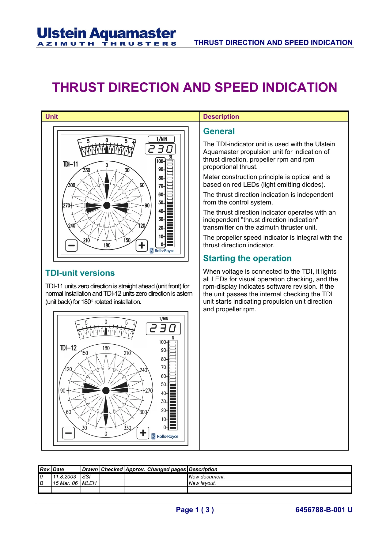
- Thrust Direction Indicators TDI-11 and TDI-12
- Hand Held Terminal (HHT) and HHT interface panel HIP006
- Hydraulic unit X8, lubrication unit X9, expansion tank X5, gravity tank X108
- Shaft brakes XB1 and XB2, draining pump starter
- Sin-cos potentiometer azimuth feedback, feedback transmitter B3, TDI transmitter B4
- Maintenance controller MCH.01, local control panel for maintenance pump
How the Manual is Organised
The Aquapilot service manual opens with general rules and terminology, then moves into maintenance and check lists with a defined inspection and lubrication programme for the control system. The settings and adjustings chapter introduces the Hand Held Terminal and its menu structure – I/O calibration, parameters, signals, function curves and ramp delays, watch, log and bus signals – which is the tool used throughout the tuning sections that follow.
From there the manual is split by subsystem: control devices at the operator level, interfaces to other control systems, then the CANMAN applications for the ACU and BCU, and finally the hydraulic and instrumentation drawings, GA and dimension drawings, installation and storage instructions, interconnection diagrams and the part list. Because each section carries its own drawing and revision references, a technician working on a specific node can go straight to the relevant subsection rather than searching through a combined chapter.
Delivery
IMAGES PREVIEW
This Rolls-Royce Ulstein Aquapilot UUC355 FP Service Manual and User Guide is delivered as an instant PDF download. There is no shipping and no waiting – the file is available immediately after checkout and can be opened on any device, viewed on screen, or printed for the workshop and the engine control room. Keeping a printed copy of the Aquapilot UUC355 FP service manual at the ACU cabinet and another in the bridge saves time on every fault, tuning adjustment and inspection.
Reviews
There are no reviews yet.