
Sabreliner NA-265 Series Structural Repair Manual NA-66-1032 Rev 10
Original price was: $37.95.$22.95Current price is: $22.95.
Sabreliner Corporation Structural Repair Manual Report NA-66-1032, Revision 10 (16 March 1990), covering approved airframe structural inspection, damage limits, and repairs for NA 265-40, -60, -60A, -60SC, -65, -70, -80, -80A, and -80SC airplanes.
Description
Sabreliner NA-265 Series Structural Repair Manual NA-66-1032 Rev 10
This download is the Sabreliner NA-265 Series Structural Repair Manual NA-66-1032 Rev 10 issued by Sabreliner Corporation as Report No. NA-66-1032. Original issue is dated 1 January 1967; Revision 10 is dated 16 March 1990. The manual is written to ATA Specification No. 100 and is intended for maintenance personnel who inspect, classify, and repair structure on NA 265 series airplanes. It is used together with the applicable maintenance manual and is not a spare-parts catalog.
Coverage includes airplanes built as NA 265-40 (S/N 282-1 and subsequent, including STC SA1674CE), NA 265-60 (S/N 306-1 and subsequent, including STC SA687NW), NA 265-65 (S/N 465-1 and subsequent), NA 265-70 (S/N 370-2 through -6, -8, and -9), and NA 265-80 (S/N 370-1 and -7, and 380-1 and subsequent, including STC SA847NW). Station diagrams, repair indexes, and damage charts also address the related NA 265-60A, -60SC, -80A, and -80SC configurations. Only installations made during manufacture are reflected. Changes made after delivery are not included.
File Details
- Manual type: Structural Repair Manual
- Brand / models: Sabreliner NA 265-40, -60, -60A, -60SC, -65, -70, -80, -80A, -80SC
- Document number: Report No. NA-66-1032
- Revision / date: Revision 10, 16 March 1990 (original issue 1 January 1967)
- Language: English
- Page count: 760
- File format: PDF
What Revision 10 Added
The 16 March 1990 revision notice lists the changes folded into this issue of the Sabreliner NA-265 Series Structural Repair Manual NA-66-1032 Rev 10: incorporation of Temporary Revision 89-1; an updated List of Effective Pages format; revised landing gear shock strut procedures; addition of Batts repair; Acres fastener sleeve kit numbers; a revised sealants table; a new main entrance door repair; a revised elevator balance procedure; revised windshield and window damage limits; overwing fairing delamination limits; and flaps sonic doubler repair. A later temporary sheet dated 29 September 2000 inserts Service Information Letter No. 57 at 51-30-00.
Airplane Measurement System
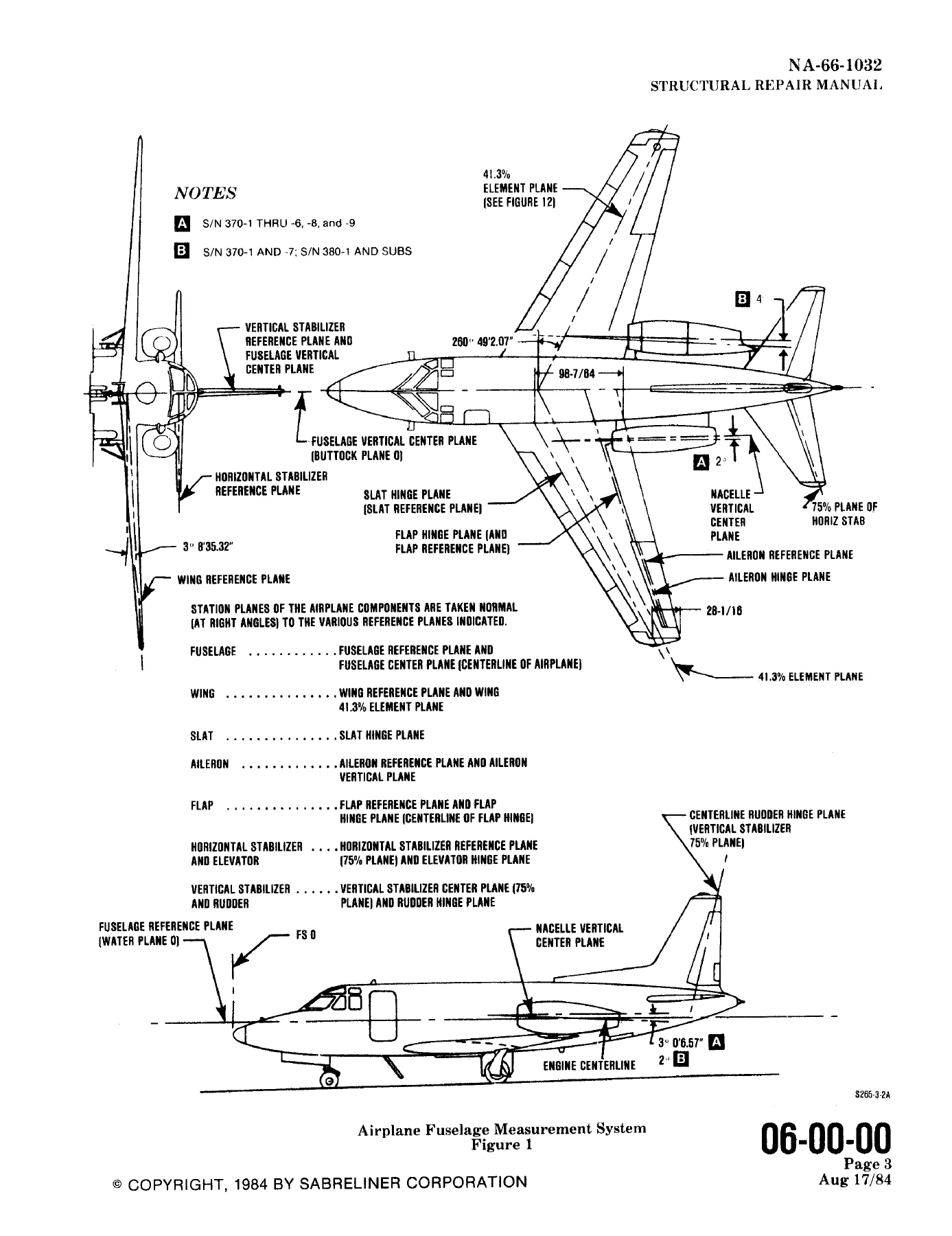
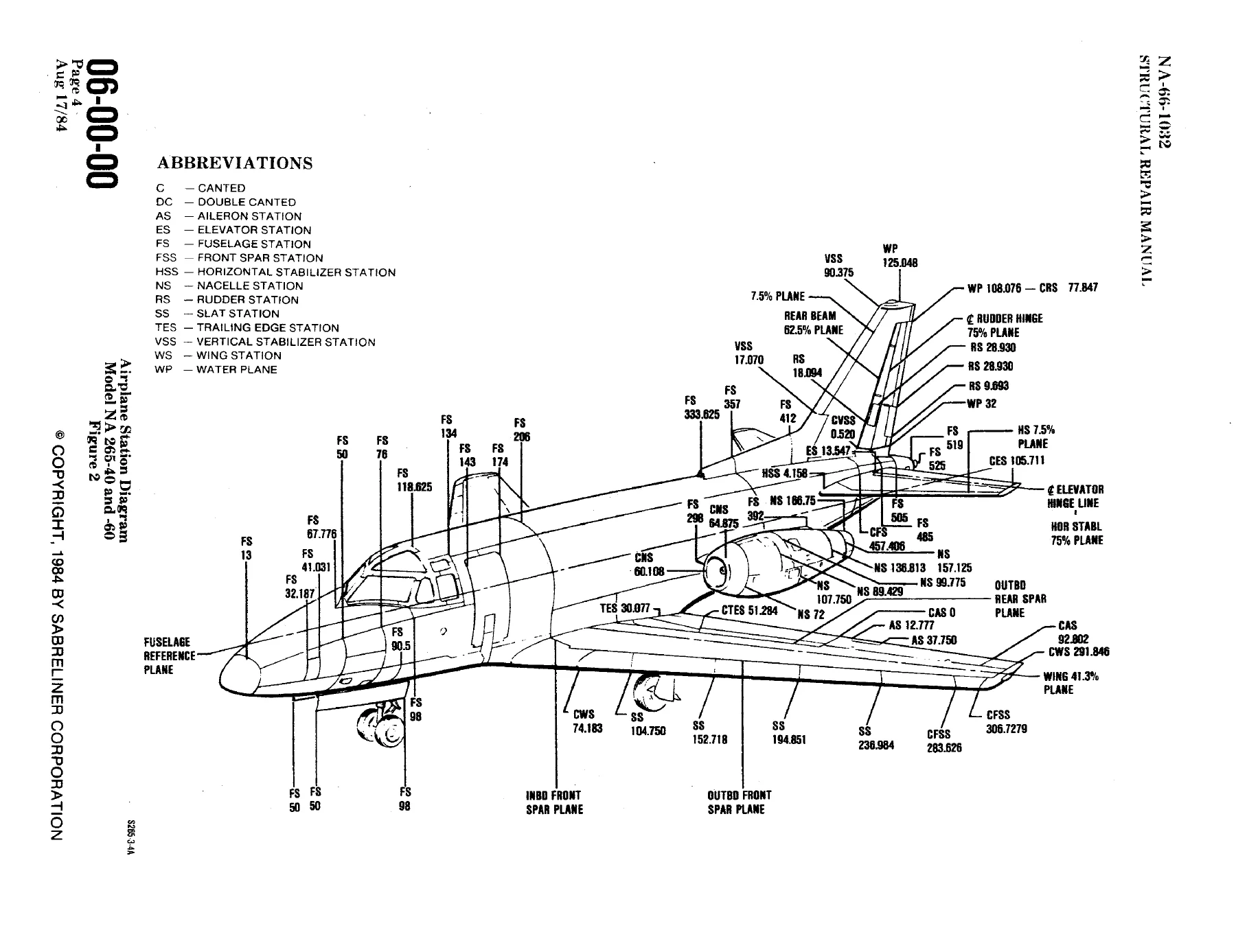
Chapter 6 explains how every repair location is defined. Fuselage stations run aft from station zero along the fuselage reference plane, identified on the airplane by two red flush-head screws on the right side at FS 142.375 and FS 443.125, each 2.375 in. below the reference plane. Buttock planes are parallel to the vertical center plane (positive left, negative right). Water planes are parallel to the reference plane (positive above, negative below). Wing stations are taken from the 41.3 percent element; the machined land for wing-tip attachment is given as wing station 293.158. Slat, flap, and aileron stations use their respective hinge or leading-edge planes. Empennage stations are taken from the 75 percent plane of the vertical or horizontal stabilizer, which coincides with the rudder or elevator hinge plane. Separate station diagrams are provided for the -40/-60, -60A/-60SC, -65, -70 (split by serial group), and -80/-80A/-80SC airplanes so a repair can be located without guessing which reference system applies.
Airframe Construction Covered by This Manual
Chapter 51 describes an all-metal airplane with full-cantilever wings and horizontal stabilizer and a semi-monocoque fuselage supporting an engine nacelle on each side above and aft of the wing. On NA 265-40, -60, -70, and -80 the wing box is front and rear spars, transverse ribs, and machine-milled upper and lower skins running tip to tip. Slats and leading edges are conventional rib-and-skin structure with chem-milled underslat skins. Trailing edges, flaps, and ailerons use beams, ribs, skins, and honeycomb sandwich panels. On NA 265-60A, -60SC, -65, -80A, and -80SC the leading edge and slats are replaced by an extended leading edge that adds a fuel tank, the trailing edge is new, Fowler-type flaps replace the earlier flaps, and the trailing edge houses hydraulically operated spoilers.
Vertical and horizontal stabilizers are cantilever beams, ribs, stringers, and skins; the vertical stabilizer trailing edge above the rudder is honeycomb. Rudders and elevators use a rear beam, forward stringers, ribs, skins, and honeycomb trailing edges. The fuselage uses four main longerons, secondary longerons, stringers, intercostals, conventional frames, and chem-milled aluminum skins. Nacelle construction differs by model: earlier airplanes use a main engine support beam, stainless-steel firewall, fairing doors, and an aluminum nose on an airfoil pylon; later -70 (S/N 370-1 and -7), -80, -80A, and -80SC nacelles bolt a nose section to the engine face and carry the thrust reverser in the aft fairing; the -65 uses upper and lower cowl doors and an aft fairing that contains blocker doors. The design concept stated in the manual is safe-life rather than fail-safe.
Chapters Covered
- Introduction — purpose, ATA format, model list, repair philosophy, part-number policy, revision method, and warning on non-Sabreliner approved parts
- Chapter 6 Dimensions and Areas — fuselage, wing, slat, flap, aileron, and empennage reference systems and station diagrams by model
- Chapter 32 Landing Gear — description; main and nose gear alignment inspection and procedures; wear and rebushing allowances; shock strut repair limits and procedures
- Chapter 51 Structures (standard practices) — type of construction; flight limits with restricted-life repairs and windshield damage; damage classification and causes; airframe and material inspection; load and buckle patterns; over-G, over-pressurization, and hard-landing inspection; overheat inspection with hardness and tension testing; airplane alignment and elevation checks; structural joint wear, rebushing, and Acres fastener sleeves; aerodynamic smoothness and filler; fuselage and nacelle sealing (pressuretight, fumetight, flame-resistant, faying-surface, exterior watertight); adhesive bonding and honeycomb filler repair; corrosion control (general airplane, speed brake and landing-gear doors, nacelles, battery compartment, wing tanks and magnesium, exterior); materials and fabrication; fastener torque, rivets (high-shear, driven pin, blind pull, Cherrymax, Cherrylock, CR-762, CCR-264, Chobert), mechanical fasteners (high-shear blind bolts, Jo-Bolts, Hi-Lock, screws, turnlocks, inserts); repair support and alignment; developing typical repairs with fastener and joint calculations and mechanical-property tables; typical examples (constant-thickness skin, crack, chem-milled skin); general repairs including secondary structure, negligible holes, honeycomb trailing edges, glass-fabric-reinforced plastic, and Batts repair; restricted-life conversions; negligible-damage rework for dents, scratches, nicks, corrosion, cracks, and holes
- Chapter 52 Doors — door repair indexes and skin-gap diagrams; main entrance door identification and stop inspection/repair (including earlier serials before S/B 3); landing-gear door allowable/negligible damage and repairs
- Chapter 53 Fuselage — master repair indexes by model group; negligible damage; forward, intermediate, and aft fuselage indexes; main-frame, auxiliary-structure, plates and skins, and attach-fitting repairs (including main landing-gear door beam, external-power receptacle, and speed-brake hinge hole elongation)
- Chapter 54 Nacelles and Pylons — structural identification by model; master and component repair indexes; negligible damage; nacelle-door replacement on specified models; auxiliary structure, plates and skins, and attach-fitting repairs
- Chapter 55 Stabilizers — horizontal stabilizer, elevator, vertical stabilizer, and rudder identification; master indexes and skin-gap tolerances; negligible damage; component repair indexes; elevator static balancing and balance procedure; rudder static balancing (0–5.25 in.-lb trailing-edge heavy on -40/-60/-60A/-60SC/-65; 0–5 in.-lb nose heavy on -70/-80/-80A/-80SC)
- Chapter 56 Windshields and Windows — master indexes; plastic windshields on NA 265-40 S/N 282-1 through -35 (P/N E-1117-1/-2) versus glass windshields on later -40 and remaining models (P/N 265-318202-13/-14); corner, eyebrow, and aft cockpit windows; cabin windows; negligible and one-time-flight damage limits; upper aft acrylic panel repair
- Chapter 57 Wings — box, leading edge, trailing edge, slats, ailerons, flaps, and spoilers by model group; master indexes and skin-gap diagrams; negligible damage and overwing fairing delamination limits on extended-tip models; rotating the wing; wing-tank sealing (groove injection, fueltight faying surface from -65°F to 200°F, joint splices, leak stop, fastener close-out, leak testing); stripping the wing; slat-track and flap-track maximum wear; flight-surface repairs including flaps sonic doublers
- Chapter 78 Exhaust — thrust-reverser identification and component locators; wear allowances for latch hooks, guide pins, drive links, and related hardware on specified models; deflector-door contact requirements; reverser repairs; support-cradle data for later -70/-80 family airplanes
Taken together, the Sabreliner NA-265 Series Structural Repair Manual NA-66-1032 Rev 10 gives the repairman station geometry, damage classification, negligible-damage charts, master repair indexes tied to Sabreliner drawing numbers and material callouts, typical-repair calculation methods, and illustrated repairs for doors, fuselage, nacelles, pylons, stabilizers, windows, wings, landing-gear structure, and thrust-reverser structure. Chapter 51 is the common toolkit; Chapters 32, 52 through 57, and 78 apply that toolkit to each airframe group.
Inspection and Repair Limits You Will Use
After a hard landing, over-G, or over-pressurization event the manual directs inspection of listed critical areas on fuselage and wing, model by model. Overheat work combines visual checks for buckles, canning, and primer discoloration with hardness and tension testing. Alignment work uses elevation-check diagrams with stated allowable differences between left and right points (examples printed on the diagrams include 1/4 in. and 1/2 in. limits at specified stations). Structural joints have allowable-wear and rebushing data plus Acres sleeve selection, length adjustment, grinding, and restricted-application rules.
Sealing coverage is specific: pressuretight and liquidtight joints, fumetight work in two temperature bands (-65°F to +225°F and 250°F to 400°F), flame-resistant sealing, removable-door sealing, faying-surface sealing, and exterior watertight sealing, plus wing-tank groove injection and fueltight faying-surface work. Negligible-damage figures define what may be blended or stop-drilled versus what must be repaired. Restricted-life repairs and flight limits with structural or windshield damage are stated so a temporary repair is not flown beyond the published envelope. Elevator and rudder balance procedures after structural work are included so control-surface mass properties are restored to the printed inch-pound limits.
Parts Policy Printed in the Manual
The introduction warns that only Sabreliner parts or Sabreliner-approved parts from approved sources are to be used. Government surplus, salvaged, or undocumented parts are called out as unsuitable even if they originated as Sabreliner hardware, because service history and hidden damage cannot be verified. This manual must not be used to identify spare parts by number; the Sabreliner Illustrated Parts Catalog is the source for complete part numbers. Numbers appearing here are identification aids only and are often incomplete.
Get the Manual and Start the Repair
With the Sabreliner NA-265 Series Structural Repair Manual NA-66-1032 Rev 10 a technician can locate a damaged skin, frame, door, nacelle, stabilizer, window, wing box, slat, flap, or thrust-reverser fitting by station, decide whether the damage is negligible, classify the repair, calculate fastener and joint strength from the Chapter 51 tables, apply the illustrated repair, restore sealing and aerodynamic smoothness, and rebalance control surfaces where required. Using the published damage limits, torque data, wear allowances, and model-specific indexes keeps the airplane inside the procedures Sabreliner Corporation issued for these NA 265 airframes. After payment the file is delivered as an instant PDF download—no shipping wait—viewable on any device and printable for the hangar bench.
Reviews
There are no reviews yet.