
Sakura DRS-601 Automatic Slide Stainer Service Manual 1993 English PDF
Original price was: $34.95.$19.95Current price is: $19.95.
Complete English service manual for the Sakura DRS-601 Automatic Slide Stainer (Control No. K16-010-00, dated April 20, 1993). Covers specifications, electric circuits, mechanical drive, water supply/drain, testing, adjustments, troubleshooting, disassembly and exploded views for the DRS-601.
Description
Sakura DRS-601 Automatic Slide Stainer Service Manual
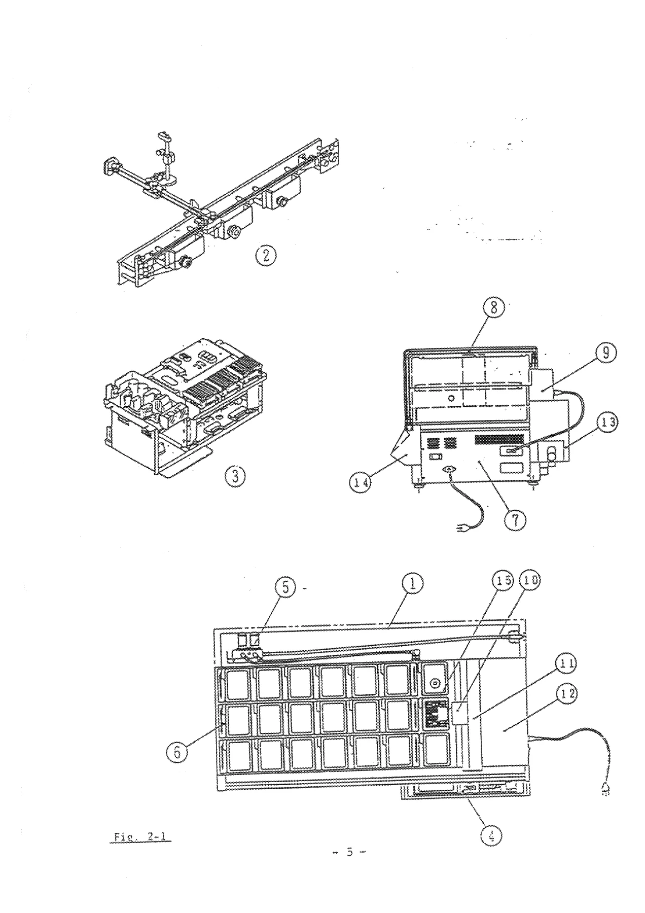
This is the English-language Service Manual for the Sakura DRS-601 Automatic Slide Stainer, issued April 20, 1993 under Control No. K16-010-00. It is the technical reference used for the ongoing maintenance, calibration, electrical diagnosis and mechanical repair of the DRS-601 slide stainer, covering the full instrument from the carrier drive system and motor control electronics down to the water supply circuit and exploded parts views.
File Details
- Manual type: Service Manual
- Brand: Sakura
- Model: DRS-601 Automatic Slide Stainer
- Language: English
- File format: PDF
- Page count: 160 pages
- Control No.: K16-010-00
- Date: April 20, 1993
Chapters Covered
- 1. Specifications — Components and Function, Electrical Specifications, Actuator, Input Keyboard, Display, External Dimensions, Weight, Environmental Conditions, Options
- 2. Outline — Main Construction, Control System (Power supply, Mother Board, Main Board, Switch Board, LCD Control Module, I/O Board, Motor Control Module, Motor Driver, Positioning Sensor, Rotation Detecting Sensor, Stepping Motor, Solenoid Valve, Fume Controller)
- 3. Operation Principal — Outline, Control of Carrier Movement, Carrier Movement between Stations, Carrier Up/Down Movement, Position Detection, Rotation Detection, Stepping Motor, Running-water Rinsing, Fume Controller
- 4. Electric Circuit — Power Supply Section, Mother Board, Main Board, Switch Board, LCD Control Module, I/O Board, MCM Board, Stepping Motor Driver, Positioning Sensor, Rotation Detecting Sensor
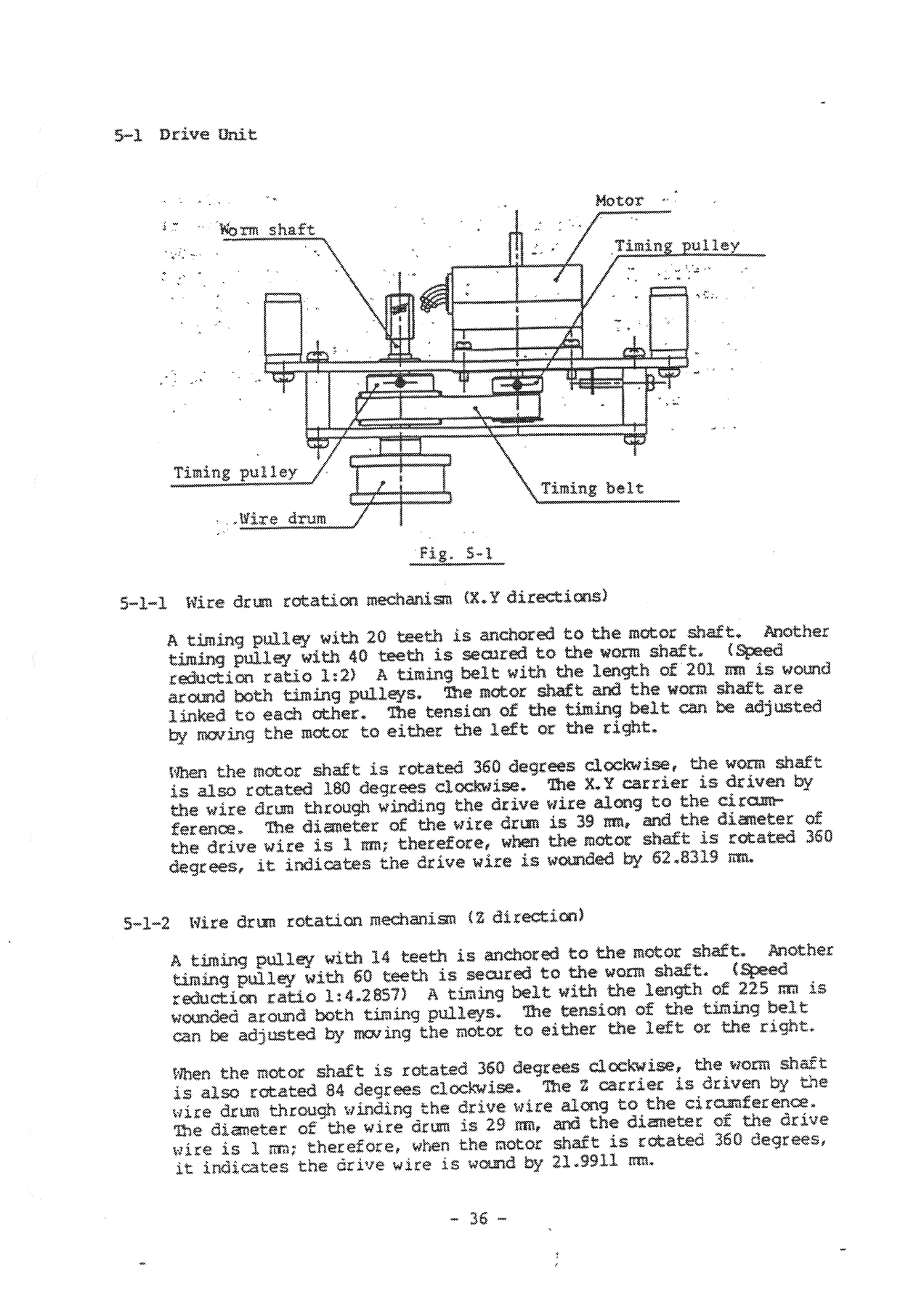
- 5. Mechanical and Water Supply/Drain Circuit — Drive Unit, Wire Drum Rotation Mechanism, Original Position and Proximity Detection, Coupling, Carrier Drive Mechanism (X/Y/Z), Pulley Rotation Detection Mechanism, Washing Container, Water Supply and Drain Circuits
- 6. Testing — System Test, Original Position Adjustment, Maximum Consumption Current, Key Switch Test, LCD Display Test, User RAM Test, Operational Performance Tests, Test Program Setting, User Program Initialization
- 7. System Alarm, Troubles, and Troubleshootings — Warning, Error Message, Error List, Error Numbers and Contents, Troubleshooting Guide
- 8. Adjustment — Instrument Level, Drive Unit, Timing Belt Tension, Worm Gear Backlash, Worm Shaft, Worm Wheel Shaft, Positioning Sensor Unit, Rotational Sensor Unit, Drive Wire Tension (X/Y/Z), Y Axis and Guide Roller Base and Z Axis Fixation, Carrier Position (Original Point), Electrical Components and Units, Board Rack, LCD Module Contrast
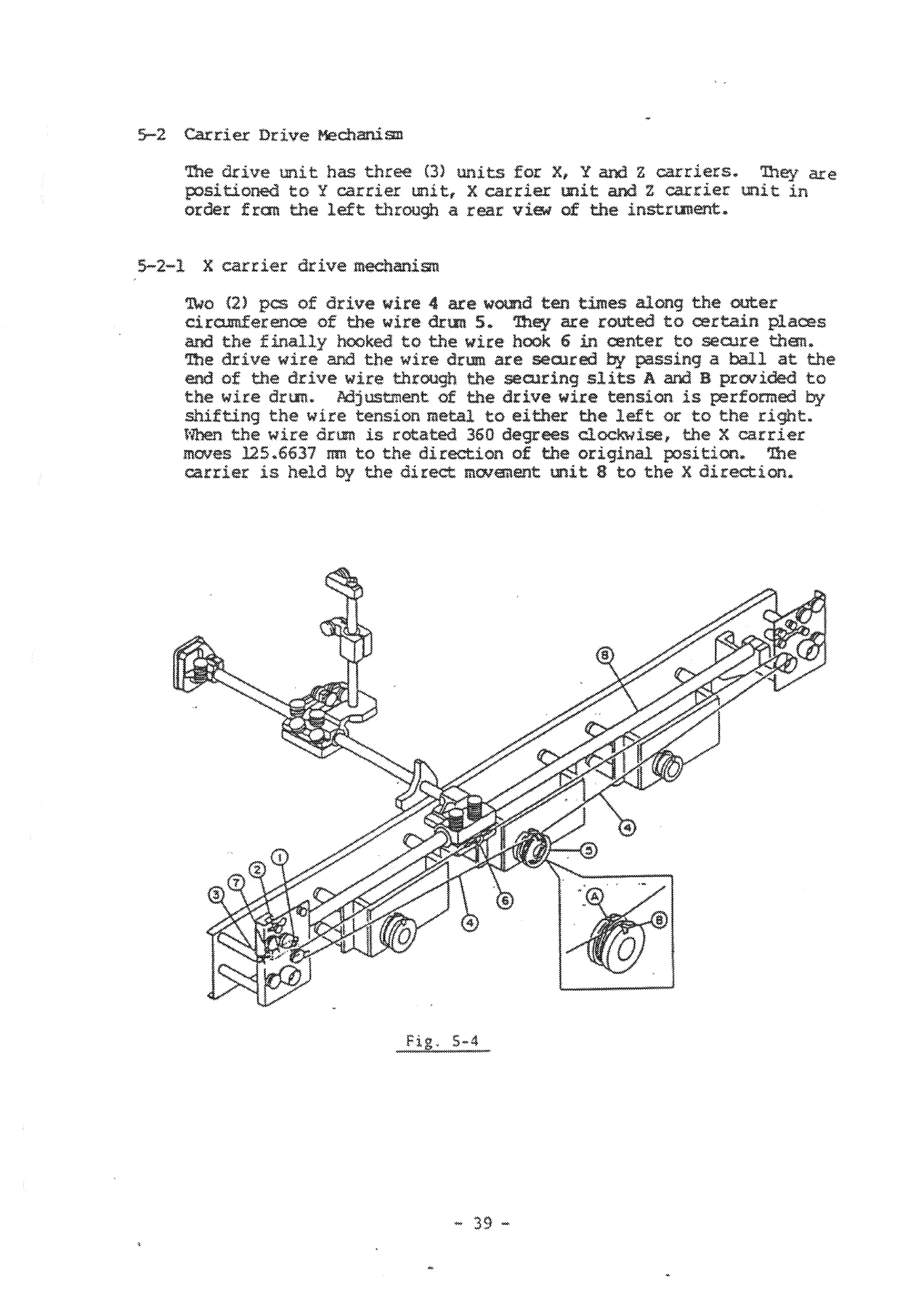
- 9. Disassembly, Assembly and Readjustment — Outer Casing, Tube Fittings, Solenoid Valve, Needle Valve Unit, Washing Nozzle, Coupling, X/Y/Z Drive Wire, X/Y/Z Linear Bearing and Shaft, Drive Unit, Control Panel Unit, Power Panel, Control Unit, Removal of Connectors
- 10. Cleaning and Lubrication
- 11. Electrical Wiring Diagrams
- 12. Exploded Views and Parts List — Casing and Tray, Water Supply Piping, Control Panel, Control Unit, Drive Unit, Drive Mechanism (1)-(3), Drive Wire Route (1)-(3), Accessories, DE-31
The document takes a technician through the DRS-601 as a complete system rather than a single subsystem. Each of the three motion axes — X (left/right), Y (front/back) and Z (up/down) — is documented end-to-end: the five-phase stepping motor, worm gear reduction, wire drum and drive wire, linear bearing and shaft, positioning sensor, rotation detecting sensor, and the MCM board that ties them together. Wiring pin assignments for the mother board, main board, switch board, LCD control module, I/O board and MCM board are printed as connector tables, so board-level signal tracing and connector re-seating can be done without guessing. The exploded views and parts lists at the back give callout part numbers for the casing, drive unit, drive mechanism, wiring route, control panel and accessories.
What This Manual Enables You to Do
The DRS-601 is a 3-axis robotic stainer, so most of its service work sits in three areas: keeping the carrier positioned correctly over all 21 stations, keeping the running-water rinse and drain circuits clean and leak-free, and keeping the motor control electronics healthy. This manual supports all three. You can adjust the original point (Home position) so the slide basket sits centred over each solution container, set the X/Y/Z drive wire tension with a spring gauge or digital tension meter, correct worm gear backlash, replace the wire drum coupling, re-time the timing belts, and re-seat the boards in the rack with the correct alignment.
On the electrical side, the manual gives the error-number structure for the MCM board and the diagnostic flow for each error — including zero-return faults, missing-position errors, motor-stop errors during normal movement, and the power-out warning. The Maintenance Mode is fully documented: Test Max Current (with measured current ranges for 100 V, 115 V, 220 V and 240 V supplies), Test Key Switch, Test Display, Test RAM, Test Motion, Set Test Program and Clear Memory. The user RAM initialization procedure, including the lithium battery removal and C20 discharge step, is given so stubborn error 125/126/127 conditions can be cleared correctly rather than by trial.
The fume controller, the two independent washing containers with their solenoid valves, the needle valve and check valve assembly, and the drain routing are all covered with adjustment and disassembly steps, so the fluid path can be serviced without removing components that do not need to come off.
Additional Reference Material Included
- Original position sensor logic for X, Y and Z axes, including the difference in direction between X/Y and Z sensing
- Rotation detection sensor wiring and the set/reset signal assignment per axis
- Board-level jumper, DIP switch and rotary switch settings for the main board, MCM board and I/O board
- Z-axis stepping motor driver current adjustment (VR1 setting) with notes on over-torque and under-torque symptoms
- Connector type guide (Type A, B, C, D) with the correct removal and re-insertion method for each
- Production-change notice covering the motor control module F50-370-00 to motor control board F50-693-00 transition and motor driver compatibility
Why This Manual Matters for DRS-601 Service
The DRS-601 uses open-loop stepping motor control with rotation-detection feedback as a protection circuit. If a carrier slips and that slip is not caught, every subsequent station position drifts — so a service procedure that ignores the original-point adjustment and the rotation detection chain will produce an instrument that looks fine on the bench and misbehaves in a staining run. This manual documents both ends of that chain: the mechanical original-point search (Z, then Y, then X) and the MCM rotation detection logic that stops the motor and raises an alarm if pulses do not come back at the expected interval. Followed in order, the adjustment chapter keeps the whole motion system coherent.
Wiring is another area where the printed pin assignments save time. Signal names, direction (IN/OUT) and the function of each pin are given for the mother board, main board, switch board, LCD module, I/O board, MCM board, stepping motor driver, positioning sensor and rotation detecting sensor, along with the output-confirming LEDs on the driver and MCM connectors. That makes it possible to verify a suspected board in place rather than swapping parts.
IMAGES PREVIEW
Instant PDF Delivery
The Sakura DRS-601 Automatic Slide Stainer Service Manual is delivered as a downloadable PDF immediately after purchase — no shipping, no waiting for a physical copy, and no restrictions on reading it on a workshop PC, laptop or tablet. Pages can be printed for use at the instrument, so the adjustment procedures and connector tables can be kept next to the machine while a repair is in progress. Whether you are chasing a single error number, replacing a drive wire, re-tensioning a timing belt or rebuilding the entire carrier drive, this is the reference that keeps the DRS-601 aligned, calibrated and running.
Reviews
There are no reviews yet.