
Sandvik NC7 Series DD531 DT821 Electrical System Manual BG00203315
Original price was: $39.95.$23.95Current price is: $23.95.
Complete 380-690 V electrical system manual for Sandvik NC7 series, DD531 and DT821 underground drilling rigs. Covers the MSE electric system, Multitimer Unit A100, protector switches, transformers, contactors, sensors, maintenance routines and troubleshooting – 148-page PDF.
Description
Sandvik NC7 Series, DD531 and DT821 Electrical System Manual (380-690 V)
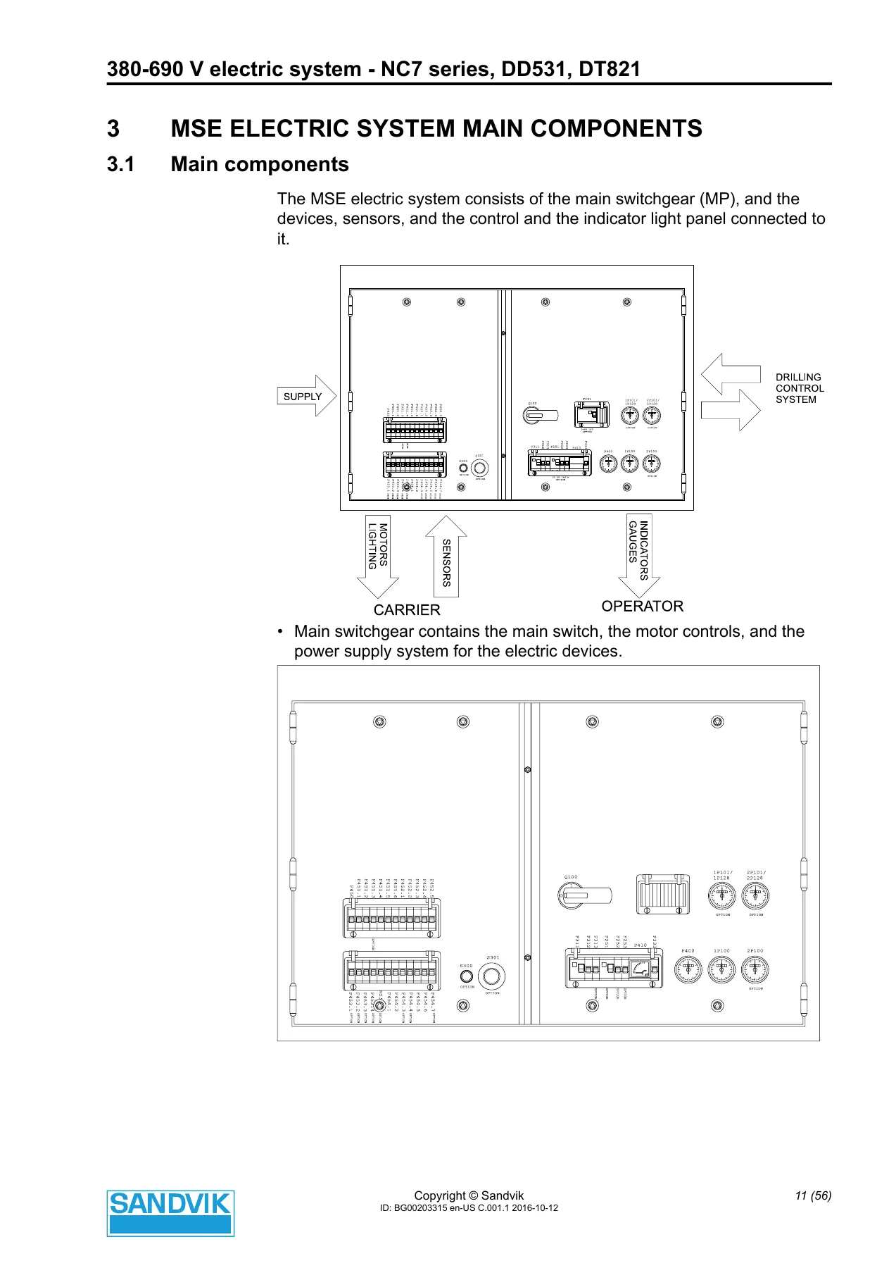
This Sandvik NC7 series, DD531, DT821 electrical system manual is the supplementary service publication for the 380-690 V electric installation fitted to these Sandvik underground drilling rigs. Issued under document number BG00203315, the PDF walks through the main switchgear (MP), the Multitimer Unit A100, the water pump and compressor control logic, the pressure and oil-level safeguards, and the operator and periodic maintenance routines needed to keep the rig’s electrical installation in safe working order. The same file also bundles several companion reference documents covering electrical schematics and symbols, AC electric motor care, corrosion protection of connectors and components, and the VYK 200 short-circuit and overload protection switch.
File Details
- Manual type: Electrical system manual – supplementary operation, maintenance and repair information
- Brand: Sandvik
- Covered equipment: NC7 series, DD531, DT821 drilling rigs
- System voltage class: 380-690 V electric system
- Language: English (the file also contains Russian-language reference sections)
- File format: PDF
- Page count: 148 pages
- Document numbers: BG00203315 (main), BG00245302, BG00210741, BG00245288, BG00173742
- Date on cover material: 2016-05-13
Chapters Covered
- 1 Introduction – purpose of the instructions, validity of the manuals, general notes on the electric system
- 2 Safety and Environmental Instructions – safety rules for working on live and dead equipment
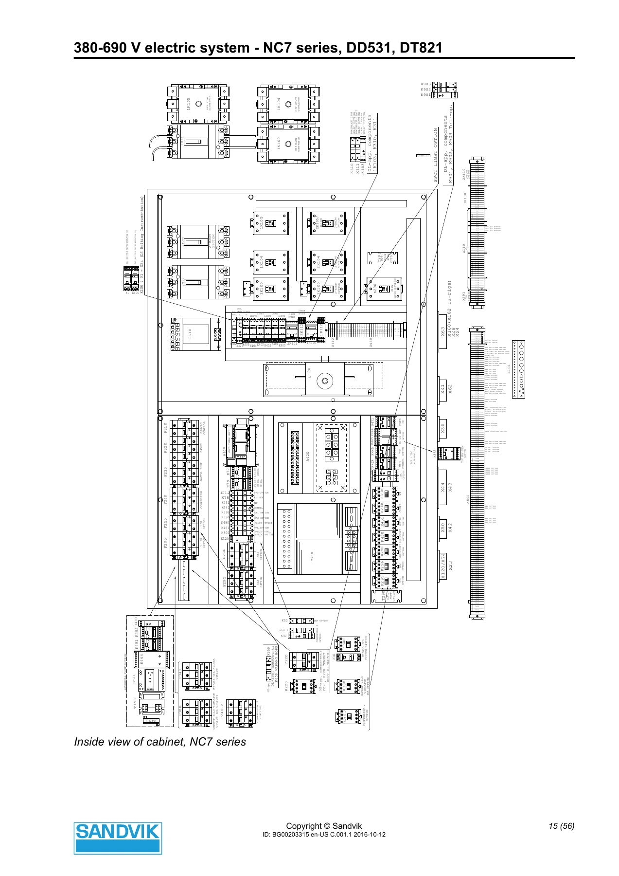
- 3 MSE Electric System Main Components – main components, layouts, protector switches, switches, gauges, circuit breakers, transformers, contactors and relays, Multitimer Unit (MTU) A100, external sensors
- 4 MSE Electric System Operation – function of the Multitimer unit, inputs and outputs for MTU, functionality description (water pump, compressor(s), water pump 2, pressure control functions, oil level control, shank lubrication, oil temperature control)
- 5 Operator’s Maintenance Procedures – safety instructions, emergency stop device checks, cabinet and connection box checks, cable and harness checks, socket and plug checks, drilling module movement prevention switch checks
- 6 Periodic Maintenance Procedures – fault current protector switch check, power supply cable check, water drainage holes, seal bushings, connections and contacts (110 VAC-1000 VAC), connections and contacts (24 VDC battery system), control system check, cleaning electric devices, checking motor terminals
- 7 Electric System Repair – procedures after a long period out of use, procedures in connection with repair
- 8 MSE Electric System Troubleshooting – powerpack does not start or stops, powerpack starts but stops after a while, powerpack main contactor clapping, working lights, 220-240 V 1-phase socket outlet, oil filling pump
- Companion Russian-language sections – electrical schematics, indications and symbols (BG00245302); electric motor operation and maintenance (BG00210741); protection of electrical and electronic components and connectors (BG00245288); VYK 200 short-circuit and overload protection switch (BG00173742)
Read together, the eight English chapters give a technician the whole electrical picture of the rig: how the main switchgear is laid out, which protector switch and circuit breaker protects which motor or circuit, how the MTU A100 delays water and air pressure monitoring, how the water pump, compressor and optional second water pump interlock with the power packs, and how faults are stored and reset. The Russian-language companion sections extend that coverage with full electrical symbol references, wiring-diagram navigation guidance, AC motor insulation and bearing maintenance procedures, connector corrosion-protection practice, and the setup and adjustment of the VYK 200 upstream protection switch.
What This Electrical System Manual Gives You
Component-level detail is one of the strengths of this publication. Every protector switch, circuit breaker, transformer, contactor, relay and external sensor is listed with its designation (F100, F230, F240, F250, F290, F310, F320, F450, F451.1 through F451.6, F452.1 through F452.5, F453.1 through F453.5, F454.1 through F454.7, F470, and so on) and a plain description of what it protects. The transformers – A410 battery charger, A420 1000 VA power transformer, T250 4500 VA service transformer, T310 control voltage transformer, T490 external pump control transformer – are documented with their ratings and thermal protection. Contactors and relays from 1K100 through K902 are catalogued, so tracing a circuit back to a specific device is straightforward.
The MTU A100 chapter is particularly useful. The input and output tables for IN 0 CH, OUT 100 CH, IN 1 CH and OUT 101 CH show the normal state of each channel when the power packs, drilling, water pump and compressor are running without faults, and clarify which signals are 24 VDC and which are momentary. Factory delay settings – 4 seconds for water pressure, 10 seconds for air pressure – and the adjustment screw range are both documented, along with the note that the multi-channel timer relay output LEDs show program status, not the actual output state.
Operators Versus Electricians – Who Does What
The manual is explicit about the split between operator tasks and electrician tasks. Operators are limited to plugging and unplugging the trailing cable, operating the product main switch, connecting one- and three-phase outlets for external pumps, and replacing bulbs in working and driving lights under the stated safety procedure. All other electrical work is restricted to professional electricians, and the manual says so repeatedly in the safety and maintenance chapters. That makes this a valuable document for both roles: it tells the operator exactly what is allowed and it gives the electrician the full component map, sensor list and fault memory behaviour they need to diagnose and repair.
Maintenance and Troubleshooting Content
The periodic maintenance chapter is practical and specific. It covers fault current protector switch testing in the main switchgear door, checking the power supply cable for wear, cuts and overheating, keeping the water drainage holes open, checking seal bushing condition and tightness, and torque-checking connections and contacts on both the 110 VAC-1000 VAC side (slip ring unit, main cabinet, electric motors, sockets, cabin heater) and the 24 VDC battery side (battery, isolation switch, starter motor and generator, glow plugs, tramming panel). Cleaning instructions distinguish between water-washed components and components that must be cleaned with compressed air or an anti-static brush, with a specific warning against high-pressure washing.
The troubleshooting chapter addresses the faults an electrician is most likely to be called for: powerpack that will not start or that stops shortly after starting, powerpack main contactor clapping caused by a weak supply network, working lights that fail, a dead 220-240 V single-phase socket outlet, and an oil filling pump that will not run. Each fault points the reader to the relevant protector switch, circuit breaker or transformer and explains what the indicator lights and thermal protectors are telling them.
Companion Reference Sections Included
Beyond the main English chapters, the file carries four Russian-language reference documents that a working electrician will come back to repeatedly. The electrical schematics section explains the symbol library, the wire colour abbreviations (BK, BN, RD, OG, YE, GN, BU, VT, GY, WH, PK, TQ), the drawing-sheet identification fields, cross-reference conventions, cable identification, and CAN bus wiring conventions with Vcc, CAN low, ground, CAN high and shield callouts. The electric motor section covers coil insulation resistance testing, safe drying methods (oven drying and heated-room drying), AC motor maintenance, and VEM motor bearing lubrication with a full grease quantity table by frame size. The connector protection section details which connectors must never be protected (VME backplane, USB, RJ45, main computer connectors), which get wax-based Pentisol 710, which get CRC 2-26 spray, and which get Ensto SR1 grease, with photographs of each connector type. The VYK 200 section documents the upstream short-circuit and overload protection switch, its earth fault sensitivity (IDn 0.03-10 A) and delay settings (0-5 s), the plug electrical protection feature, and the thermal and magnetic protection adjustment procedure with worked values (In 400 A, Io 0.63, Ir 0.95, Isd 8x).
Why This Manual Matters for Your Rig
An underground drill rig running on 380-690 V is not a place to guess. Every protector switch must be set to the right thermal value – the manual states that motor protector switches are set to 1.2x the nominal motor current for the power packs and to the nominal motor current for the water booster pump and compressor. Every delay setting must match the pressure behaviour of the water and air systems. Every earth fault relay must be tested daily. Having the correct Sandvik NC7 series, DD531 and DT821 electrical system documentation on hand means the person doing the work is reading the same designations, settings and procedures the machine was built to, rather than interpreting a generic wiring diagram. It supports fault diagnosis, planned maintenance, safety checks, and correct resetting of protective devices after a trip.
IMAGES PREVIEW
Instant PDF Delivery
The manual is delivered as a PDF download immediately after purchase, with no shipping and no waiting. It can be stored on a laptop, tablet or phone, printed for the workshop binder, and searched on screen. Whether you are a rig electrician tracing a 24 VDC control fault, an operator confirming what you are allowed to do on the electrical system, or a maintenance planner building a periodic inspection schedule, this Sandvik NC7 series, DD531, DT821 electrical system manual gives you the documented answer.
Reviews
There are no reviews yet.