
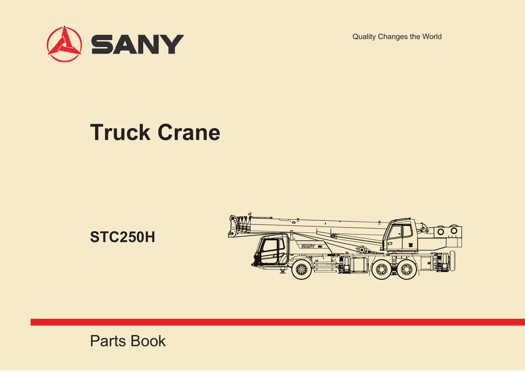
Sany STC250H Truck Crane Parts Book PDF – Illustrated Parts Catalog for Equipment 12TC20252302
Original price was: $63.95.$39.95Current price is: $39.95.
Complete illustrated Sany STC250H truck crane parts book in PDF – every group from chassis and hoisting boom to turntable, hydraulic system, jib boom and hooks, with exploded views, call-out numbers, part numbers, descriptions and quantities for equipment 12TC20252302.
Description
Sany STC250H Truck Crane Parts Book – Equipment 12TC20252302
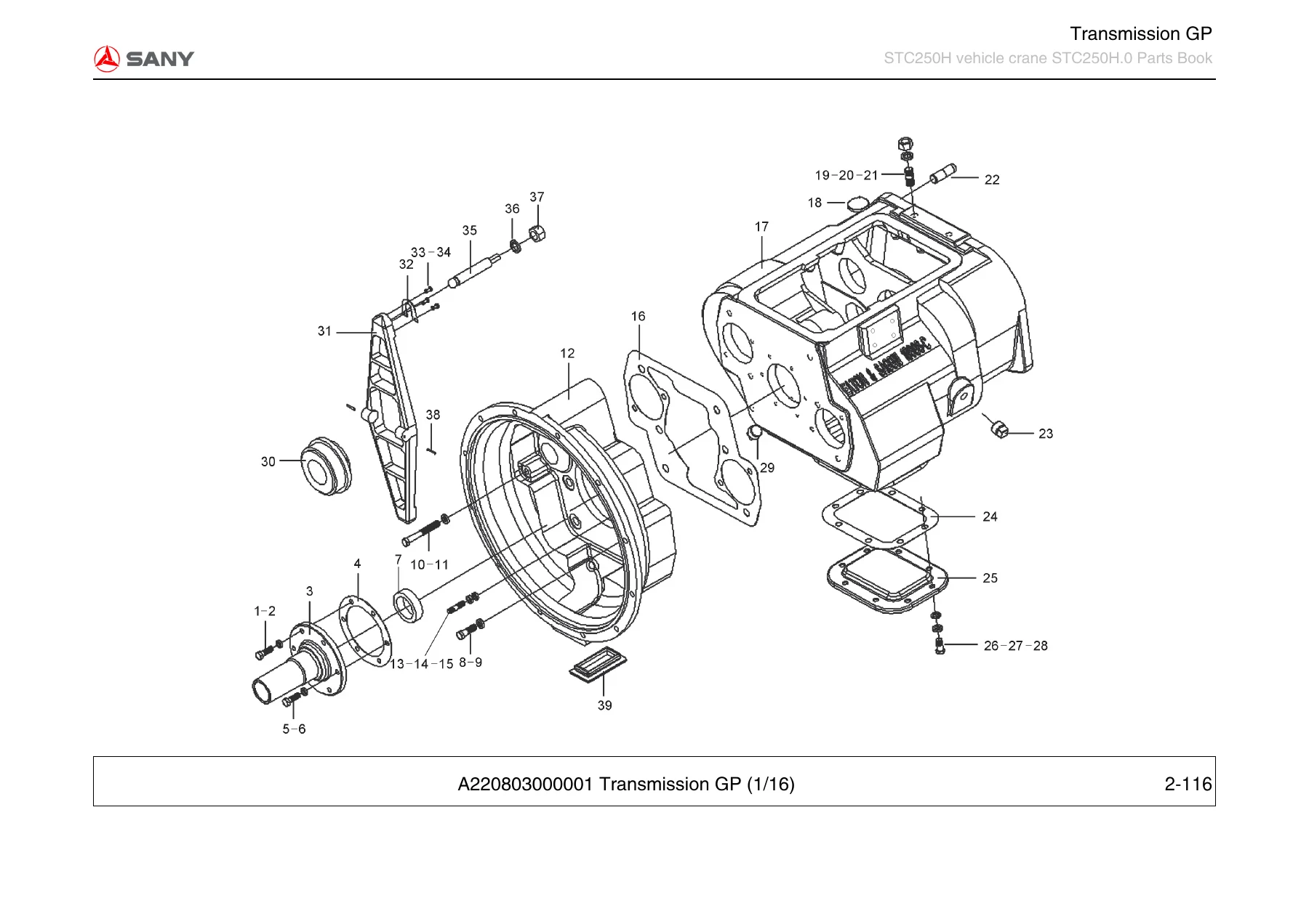
This is the illustrated parts book for the STC250H truck crane, published under equipment number 12TC20252302. It is the reference a workshop, parts counter or service technician reaches for when a component has to be identified, matched and ordered without pulling the machine apart twice. Every assembly is broken down into exploded line-art with numbered call-outs, and each call-out resolves to a part number, description, quantity and – where the factory added one – a remark note. The whole crane is covered, from the carrier chassis and running gear through to the superstructure, hoisting boom and hook blocks.
File Details
- Manual type: Illustrated Parts Book (Parts Catalog)
- Brand: Sany / SANY Heavy Industry
- Model: STC250H truck crane
- Equipment number: 12TC20252302
- Language: English (Chinese group headings retained alongside the English text)
- File format: PDF
- Page count: 657 pages
Chapters Covered
- Group 0 – Introduction
- Group 1 – STC250H vehicle crane body STC250H.0
- Group 2 – Chassis, truck crane
- Group 3 – Hoisting boom assembly STC250H.1B
- Group 4 – Layout plan, nameplate
- Group 5 – Electrical system, superstructure
- Group 6 – Operator’s cab, superstructure
- Group 7 – Hydraulic system, superstructure
- Group 8 – Turntable
- Group 9 – Jib boom STC250H.8A
- Group 10 – Hook GP
- Group 11 – Hook, aux.
Group 0 – Introduction and How the Book Works
The opening group explains how the catalog is organised and how to read it. It walks through the line-art illustration pages and the matching parts lists: the Item No. column that ties back to the call-out numbers in the drawing, the Part No. column used together with the description to positively identify a component, the Qty. column showing how many of that part sit in the assembly, and the Remark column that carries supplementary fitment notes. There is also a machine information section showing the data plates for both the truck crane chassis and the full hydraulic truck crane, with fields for VIN, product type, engine model, rated power in kW/(r/min), complete chassis kerb mass, maximum designed gross mass, date of production and factory number. Parts ordering is documented with both the distributor route and the online portal route, and the distributor contact block for SANY Mobile Cranes is printed in full.
Group 1 and Group 2 – Vehicle Crane Body and Truck Crane Chassis
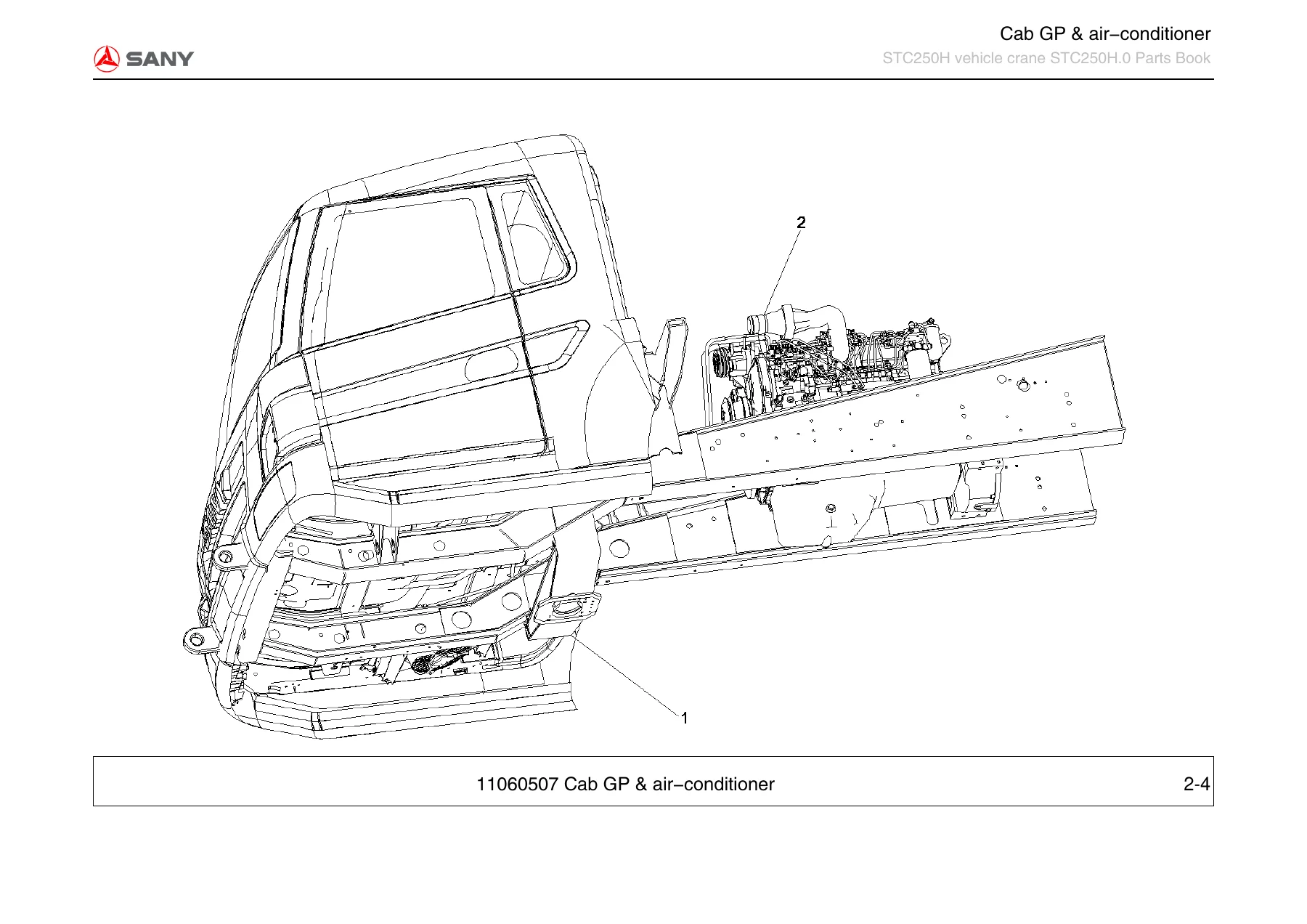
Group 1 is the top-level breakdown of the crane itself, listing the chassis, hoisting boom assembly, nameplate layout, superstructure electrical system, operator’s cab, superstructure hydraulic system, turntable, jib boom and both hook groups as discrete orderable assemblies. Group 2 then opens the carrier out into its major systems: cab group and air-conditioner, nameplate and label installation drawing, power system device, power train device, chassis control device, frame construction system device, axle suspension, chassis hydraulic system, chassis electrical system to EURO III, brake system device and steering system device. From there the chassis is detailed page by page – cab assembly and white-body group, inner and outer ornamentation, instrument panel for the narrow crane in three parts, carpet assembly, guard plates, sealing, seats, glass, mirrors, bumpers, flowguide, handrails, front panel and the full cab electrical system with rocker switches, glass lifters, horns, door lamps and harnesses. The engine and suspension section, oil supply system, air intake system, exhaust system, cooling system and combination radiator follow, then the clutch and control mechanism, transmission and control device, the detailed transmission gear train pages, drive shaft device and the chassis control linkage with valve controllers and two-force rods.
Group 2 Continued – Frame, Outriggers, Axles, Brakes and Steering
The frame construction system pages cover the carriage weldment, fifth outrigger pan, boom bracket, platform, spare tyre rack, toolbox, mudguards, engine hood and the fifth outrigger cylinder. The movable outrigger assembly, horizontal outrigger oil cylinder and rear outrigger piping are broken down to seal rings, guide rings, piston rods and cylinder barrels. Suspension and axle work is covered in depth: tyre and wheel group with rim and inner/outer tyre breakdown, front bridge belt adaptor, front axle in four parts including hub, brake drum, steering knuckle, track rod arms and brake chambers, front left and right brake assemblies with shoes, camshafts, rollers and friction plates, rear suspension with compensating beam, thrust rods and steel plate springs, front suspension with damper brackets and U-bolts, and the rear and middle axle groups with differential, half shafts, hub bearings, wheel nuts and brake chambers. The chassis hydraulic system follows with the hydraulic oil tank, suction and return piping, gear pump in three exploded sections, flow collecting valve block, steel outrigger pipelines, five-way connector, rubber outrigger pipelines, multiway valve in two sections and the central swing joint. Chassis electrical to EURO III and the brake system device – including air reservoir bandages, desiccator piping, regeneration cylinder pipe and check valve steel pipe – close out the carrier.
Group 3 – Hoisting Boom Assembly STC250H.1B
The boom group is the largest single section in the book. It starts with the complete hoisting boom assembly and then works through each boom section in turn – one-section, two-section, third, fourth and five-section booms – with the sliding plates, cushion blocks, wear pads, adjustment shims, support blocks, pin shafts, retainers and rope holder rollers that sit between them. Rope holder rollers, cord rollers, pulleys and guide pulley assemblies are given their own exploded pages with bearings and retainer rings. The telescopic mechanism is documented across three pages, covering the four-section boom extending and shrinking ropes, the five-section boom arm-stretch and arm-contract cords, pulley shells, guide wheel support assembly, cylinder bracket and the slide wheel assemblies. Both telescoping cylinders are broken down to piston rods, guide sleeves, seal sleeves, oil flow rings, pistons, O-rings, B3-ring, GS-ring, MD-ring, UNP-ring and UP guide ring level, along with the steel pipe running inside the telescopic cylinder.
Group 4 and Group 5 – Nameplates and Superstructure Electrical System
The layout plan and nameplate group lists the hoisting position schematic, outrigger operation plates for left and right, wire rope operation hint, service hotline plate, turntable alignment decals, lubricating point plate and the truck crane name plate. The superstructure electrical system covers the boom electrics and the turntable electrics: height limiter, ATB cable weight, counterweights and their hammer bodies, boom harnesses in multiple part numbers, the turntable harness, solenoid valve harness, circuit control panel, conducting ring component, cluster, rear clearance lamp assembly and the jib electrical diagram and jib harness.
Group 6 and Group 7 – Operator’s Cab and Superstructure Hydraulics
The superstructure operator’s cab group covers the cab mounting with shock pads, the control room assembly, bodywork, door group with hinges and adjusting shims, accessories, inner decoration including carpet, front instrument panel, right console, pilot handle handrail boxes, hydraulic control guard boxes, protective plates, sealing system, seat group with right and left handrails, outer decoration, narrow glass set and the leading electric system with ceiling lamp, wiper, ignition switch and rocker switch arrays, plus the warm-air device and air-conditioning system with evaporator breakdown. The superstructure hydraulic group is equally detailed: main and auxiliary winch oilway with prefill check valves, transition blocks, balance valves and plunger motors, luffing and telescoping oilway with the telescoping cylinder switch valve and electromagnetic reversing valves, return and drain piping with check valves and radiator, main valve assembly with the multiway valve broken into valve plates and relief valves, hoisting pipeline at the centre joint port, oil drain and oil return blocks, luffing balance valve, main pressure oilway with pilot valve and high-pressure oil filter, control piping with changeover valve, telescoping cylinder pipeline with balanced valves, pilot handle oil circuit with leading valves and pressure gauges, and the rotary and air-conditioner piping with gear motor and cushion valve.
Group 8, 9, 10 and 11 – Turntable, Jib Boom and Hooks
The turntable group covers the slewing lock pin, rear-view mirror, three pin-connected joints, swing mechanism with slewing bearing broken down to outer ring, inner ring, sealing strips, steel balls and separators, the swing reducer in two exploded sections, hoisting mechanism with rope guard devices and two hoisting reducers, counterweight assembly, turntable body weldment and bracket, engine shed with ladder, and the luffing cylinder in two parts with piston rod, guide sleeve, UP guide ring, MD-ring, B3-ring and GS-ring. The jib boom group documents the STC250H.8A jib across three pages, including boom support, connection plates, clamp pins, pin shafts, carrier roller shafts, pulleys and the fold plate. The main hook group and auxiliary hook group list single hook, yoke, hook cross beam, cross beam baffles, hook nut, support sleeves, pulley components and shafts, shaft end baffles, rope stop rod, shackle, retaining rings, lock plate and nameplate, plus the auxiliary hook assembly with hook body and safety latch.
Why This Parts Book Pays for Itself
Ordering the wrong part for a 25-tonne truck crane is expensive in both directions – the part you did not need, and the downtime while the right one arrives. This catalog removes the guesswork. Because every drawing carries call-out numbers that match directly to an item row, and every row carries a part number plus a description, you can identify a bracket, a seal kit, a boom wear pad or a valve plate by looking at the illustration rather than by describing it over the phone. The assemblies are broken down far enough to reach consumables: O-rings, guide rings, dust seals, shims, wear pads, bolts, washers, nuts and pins all carry their own part numbers, so a seal replacement does not become a whole-cylinder order. Where a component exists in left-hand and right-hand versions – brake assemblies, outrigger covers, cab doors, tool box doors, mudguards – the book keeps them as separate line items so the correct side is ordered first time.
What You Can Do With It
Use it to build a parts list before a scheduled service, to identify a failed component from a photo or from the machine itself, to confirm quantities when a fastener kit has to be assembled, to check whether a bracket or guard plate is still listed separately or only as part of a larger assembly, and to cross-check that the part going on the crane matches the part coming off it. The exploded views also work as an assembly guide – the order in which a swing reducer, a telescoping cylinder or a multiway valve goes back together is visible in the drawing before a spanner is picked up. It is equally useful on a laptop in the workshop, on a tablet next to the machine, or printed and left in the parts office.
IMAGES PREVIEW
Instant PDF Delivery
The Sany STC250H truck crane parts book is delivered as an instant PDF download – no shipping, no waiting on a courier, no damaged binder arriving three weeks later. Open it on any device, zoom into the exploded views as far as the drawing allows, search the part number you already have, and print only the pages you actually need for the job in front of you. Whether you are maintaining one STC250H or running a fleet under equipment number 12TC20252302, having the complete illustrated parts catalog on hand turns a parts enquiry into a two-minute lookup.
Reviews
There are no reviews yet.