
Sany SY245C9M3KH (OPT1) Hydraulic Excavator Parts Book PDF – SY024NCCM5198 Illustrated Parts Catalog Download
Original price was: $41.95.$27.95Current price is: $27.95.
Complete illustrated parts book for the Sany SY245C9M3KH (OPT1) hydraulic excavator, document SY024NCCM5198. Full exploded-view diagrams, callout numbers and part-number tables covering every major assembly from the boom and bucket to the slewing device, cab, pilot pipeline and undercarriage.
Description
Sany SY245C9M3KH (OPT1) Hydraulic Excavator Parts Book – SY024NCCM5198
This is the complete illustrated parts book for the SY245C9M3KH(OPT1) hydraulic excavator, published under document number SY024NCCM5198 and dated 2023-01-05. It is the parts identification and ordering reference that Sany supplies with the machine, and it is the same catalog a dealer parts counter uses to pull the correct component for a rebuild, a repair, or a routine replacement. Every assembly in the machine is broken down into exploded line-art with numbered callouts, and every callout is matched to a part-number table that gives the index, part number, description, quantity per assembly, and the page to turn to for the next level of detail.
Because this is the SY245C9M3KH(OPT1) parts book rather than a generic catalog, the part numbers, quantities and assembly breakdowns shown here are specific to this machine variant. If you own, service, or rebuild this exact excavator, this is the document that tells you what the factory actually put in it.
File Details
- Manual type: Illustrated Parts Book / Parts Catalog
- Brand: Sany
- Model: SY245C9M3KH(OPT1) Hydraulic Excavator
- Document number: SY024NCCM5198
- Date on document: 2023-01-05
- Language: English
- Page count: 334 pages
- File format: PDF
Chapters Covered
The catalog is organised into sixteen numbered groups plus a full alphabetical and numerical index at the back. Each group opens with an exploded-view illustration page followed by the matching part-number table.
- Group 1 – SY245C9M3KH(OPT1) Hydraulic Excavator Body
- Group 2 – Random Accessories
- Group 3 – Crawler Assembly
- Group 4 – 1.3 Bucket
- Group 5 – Coating
- Group 6 – Electric
- Group 7 – Running Control Mechanism
- Group 8 – Driver’s Cab Assembly
- Group 9 – Fuel Pump Line
- Group 10 – Alarm Lamp
- Group 11 – Slewing Device
- Group 12 – Cab
- Group 13 – Pilot Pipeline
- Group 14 – Work Device
- Group 15 – Drives
- Group 16 – Rootcloud Component
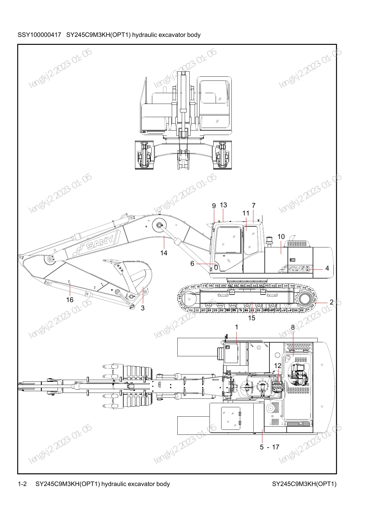
Group 1 – Machine Body
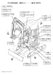
The top-level assembly page for the whole machine, with the master callout diagram showing the crawler assembly, 1.3 bucket, coating set, electrical group, running control mechanism, driver’s cab assembly, fuel pump line, alarm lamp, slewing device, cab, pilot pipeline, work device, drives and Rootcloud component as numbered sub-assemblies. Use this as the entry point before drilling into any group.
Group 2 – Random Accessories
The shipped-with-the-machine accessory list: fuses in the various ratings, the hydraulic excavator operation and maintenance manual, the accessories box, excavator certificate, Sany maintenance and guarantee booklet, spare parts drawing volume, accompanying tools, fuel filter elements, oil filter element, fuel filter and engine atlas.
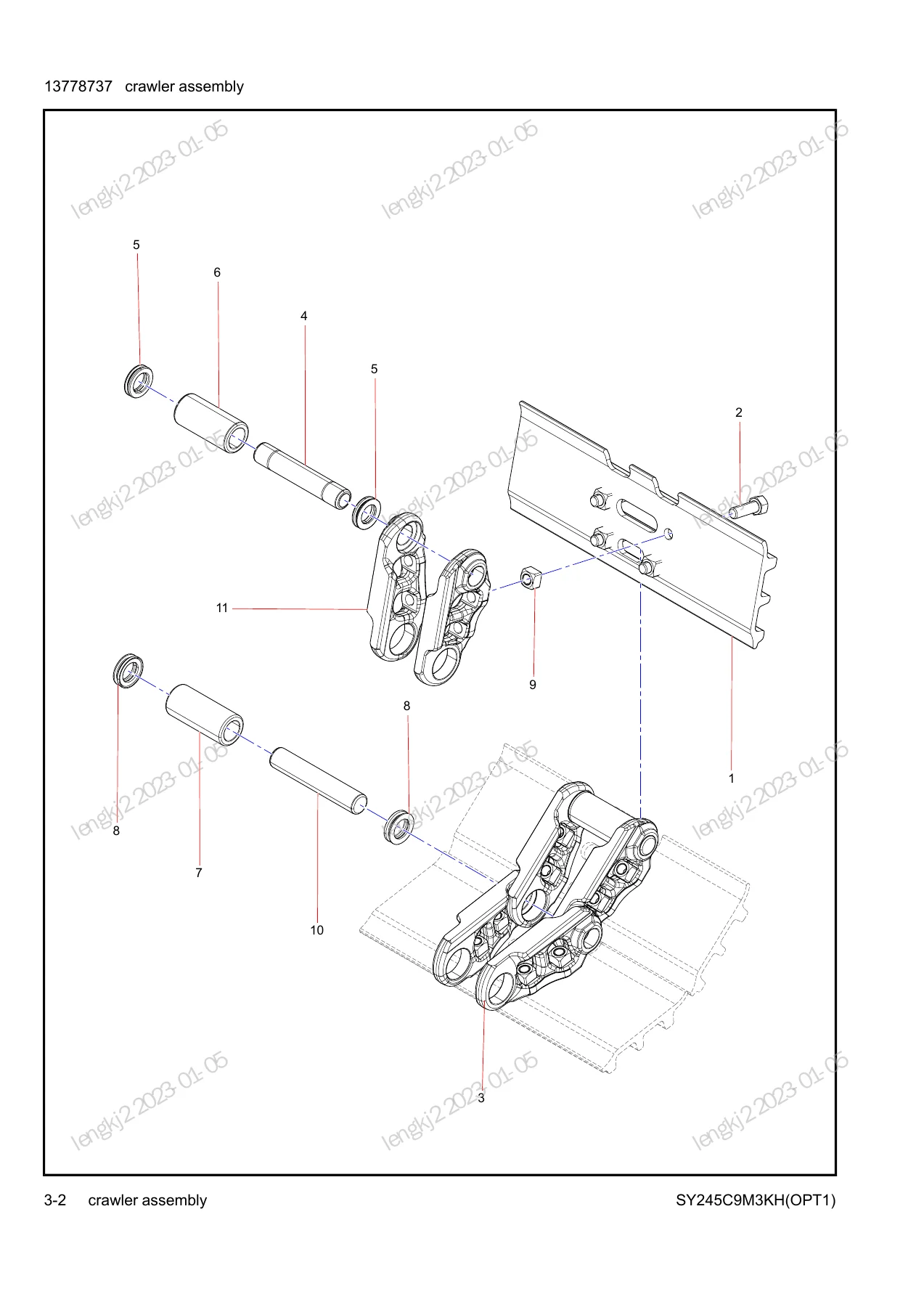
Group 3 – Crawler Assembly
Undercarriage hardware broken out into track shoes, crawler bolts, crawler chain track, main pin, main seal ring, main bushing, bushings, seal rings, check nuts, pins and the complete track unit. Exploded view shows the pin-and-bushing chain link assembly in full.
Group 4 – 1.3 Bucket
Complete bucket breakdown: shims, tooth bucket, cutter sides, bolts, washers, nuts, pins, clips and tooth bases, with the exploded view showing the tooth and adapter arrangement across the bucket lip.
Group 5 – Coating
The full decal and marking set for the machine, including hand-scald decals, anti-skid tapes, power-supply and operation decals, emergency-exit decals, warning decals for engine hood, splash, belt safety, front-window lock and tensioner, tank discharge label, nameplate, pre-start precaution decals, refrigerant-change instruction, high-voltage and power-off warnings, directional and stop-engine markings, grease-point decals, boom left and right decals, counterweight left/right and side-marker decals, hydraulic tank decal, environmental-protection marking, diesel and fuel logo plates.
Group 6 – Electric
Electrical system parts for the machine: boom harness assembly, electric box assembly, cab electrical system assembly, body harness, battery assembly, work lamp harness and lights, control box assembly, integrated box, LED indicator lamps, rotary switch, display, cab harness, relay, radio, antenna extension, control switch harness, key switch, washers, bolts, screws and nuts.
Group 7 – Running Control Mechanism
Travel and pilot control hardware including pedals, pedal backup plates and sleeves, control levers, left and right handles, connecting platform for the quartering hammer pipeline, hammer pilot pipeline, and the main valve pipeline for the travel control circuit.
Group 8 – Driver’s Cab Assembly
Cab structure and interior: cab weldment, trim assembly, electrical components, accessories assembly, glass set, air floor, air flue, skylight assembly, front window assembly, cab door hinges, cab door window and frame, sliding window, door lock and handle, side panels, rubber seals, rear-view mirror, cup holder, horn cover, A/C cover assembly, left and right inner decorations, upper trim, skylight top board and base cover assembly.
Group 9 – Fuel Pump Line
Fuel pump line components with the associated mounting and connection hardware.
Group 10 – Alarm Lamp
Alarm lamp and its mounting seat, rocker switch, relay, audible/visual warning light, bolts and screws.
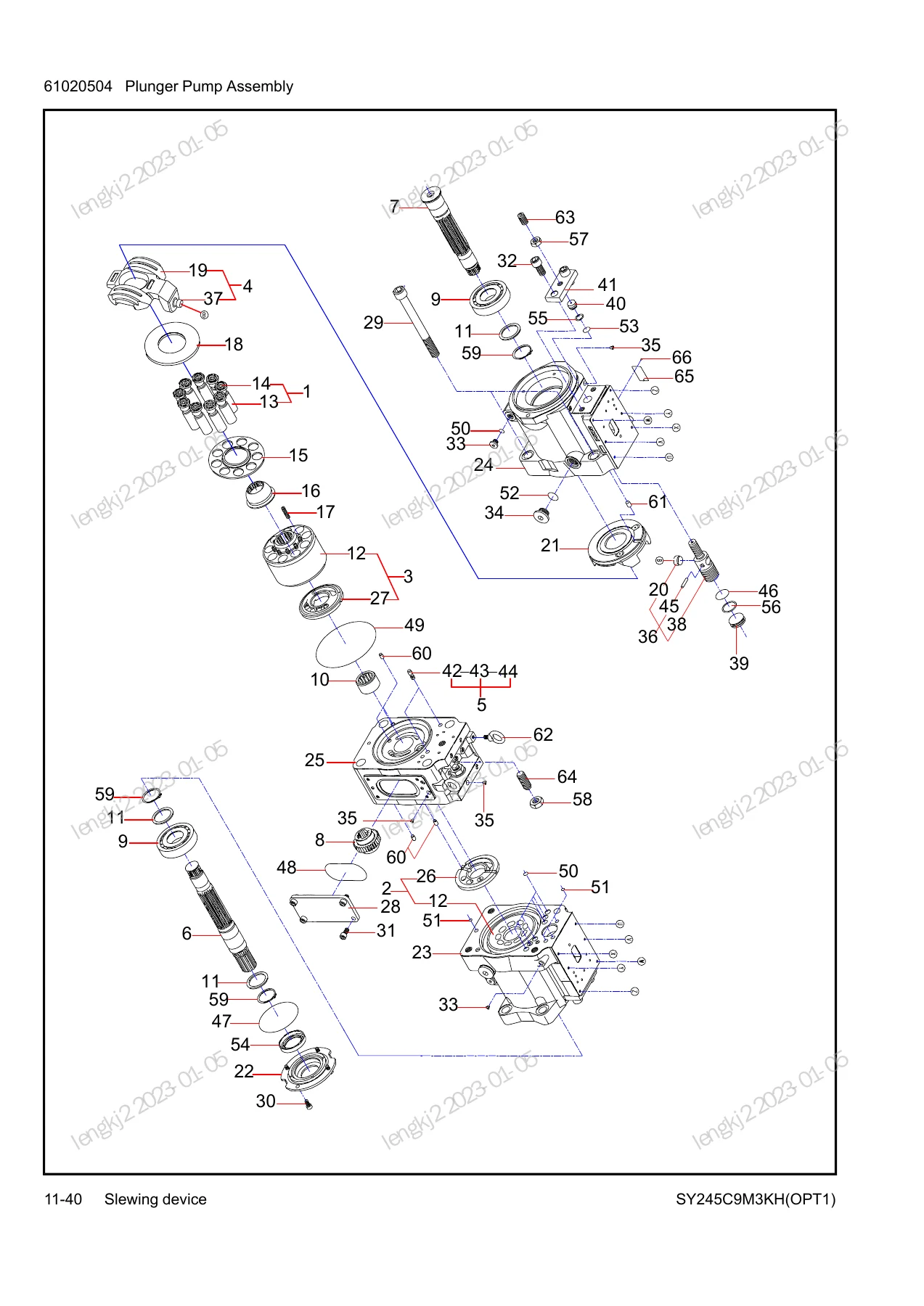
Group 11 – Slewing Device
The largest group in the book, covering the upper-structure systems: pump lines, the rotary motor and reducer assemblies, planetary carriers, the composite pump set and plunger pump assembly, multi-port valve, hydraulic fuel tank, air cleaner, oil return pipeline, counterweight, power system, damping and transmission system, exhaust system, fuel system and fuel tank, fuel water separator, cooling system and combined radiator, intake system, air conditioning electrical systems and evaporator, rotary bearing assembly, slewing ring, covering parts assembly, toolbox, rear-mirror bracket, bonnet, left rear door and right door.
Group 12 – Cab
Interior cab fit-out: floor, foot-blowing passage, fire extinguisher, seat and control box, armrests, lower base frame, mechanical suspension driver seat, rail guides, control panel and all associated fasteners.
Group 13 – Pilot Pipeline
The complete pilot and control piping network: main pump pipeline, high-pressure filter, solenoid valve pipeline, main valve pipeline, PPC pipeline, pilot-control valves, adapters, O-rings, fittings, tees, elbows, hoses and protective sleeves.
Group 14 – Work Device
Boom, arm and bucket linkage: boom, right rocker, connecting rod, bushings, dust rings, resin shims, lock pins, press plates, grease nipples, lubricating circuit, work device hydraulic tube, boom cylinder assemblies, arm cylinder assembly, bucket cylinder assembly and service kits for each cylinder.
Group 15 – Drives
Travel drive and undercarriage running gear: leading wheel assembly, tensioning equipment, carrier roller, track roller assembly, seal component, running device pipeline, reduction gear assembly, reduction part, running motor and rotary joint.
Group 16 – Rootcloud Component
Telematics hardware: T-BOX harness and GPS terminal for the region covered by this catalog.
Index
A complete alphabetical and numerical index at the back of the book listing every part number, description and the page it appears on, so a known part number can be located in seconds without scanning every group.
Why This Parts Book Matters
Ordering the wrong part for a 25-tonne-class excavator is expensive. A cylinder seal kit that is one number off will not fit the bore. A track bolt with the wrong grade will fail under load. A decal with the wrong part number will not carry the correct safety message. This catalog removes the guesswork by tying every part number to a specific callout on a specific assembly drawing of this exact machine variant. You look at the exploded view, you read the callout, you read the table, you order the number. That is the whole process.
The quantities column is also a quiet but important feature. When you are rebuilding a boom cylinder or a final drive, knowing that the assembly uses four of one seal and two of another lets you order the right count the first time rather than discovering the shortfall halfway through the job.
Who This Manual Is For
- Owners of the SY245C9M3KH(OPT1) who want to identify parts correctly before ordering
- Independent repair shops servicing Sany excavators
- Fleet maintenance departments managing spares for construction equipment
- Parts professionals cross-referencing Sany part numbers
- Rebuilders working on the boom, arm, bucket, slew, travel or hydraulic circuits
IMAGES PREVIEW
Instant PDF Delivery
The parts book is delivered as an instant-download PDF the moment your order is complete. There is no physical shipping, no waiting on a courier, and no risk of a paper copy being lost in the workshop. Download it once, save it to your phone, tablet, laptop or shop computer, and print the pages you need. If a page gets greasy in the workshop, you print another. The exploded-view drawings and part-number tables are laid out so they can be printed at full page size for use at the bench.
Whether you are ordering a single O-ring or planning a full undercarriage rebuild on your SY245C9M3KH(OPT1), this Sany parts book gives you the same information the factory parts system uses – in one searchable, printable PDF.

Reviews
There are no reviews yet.