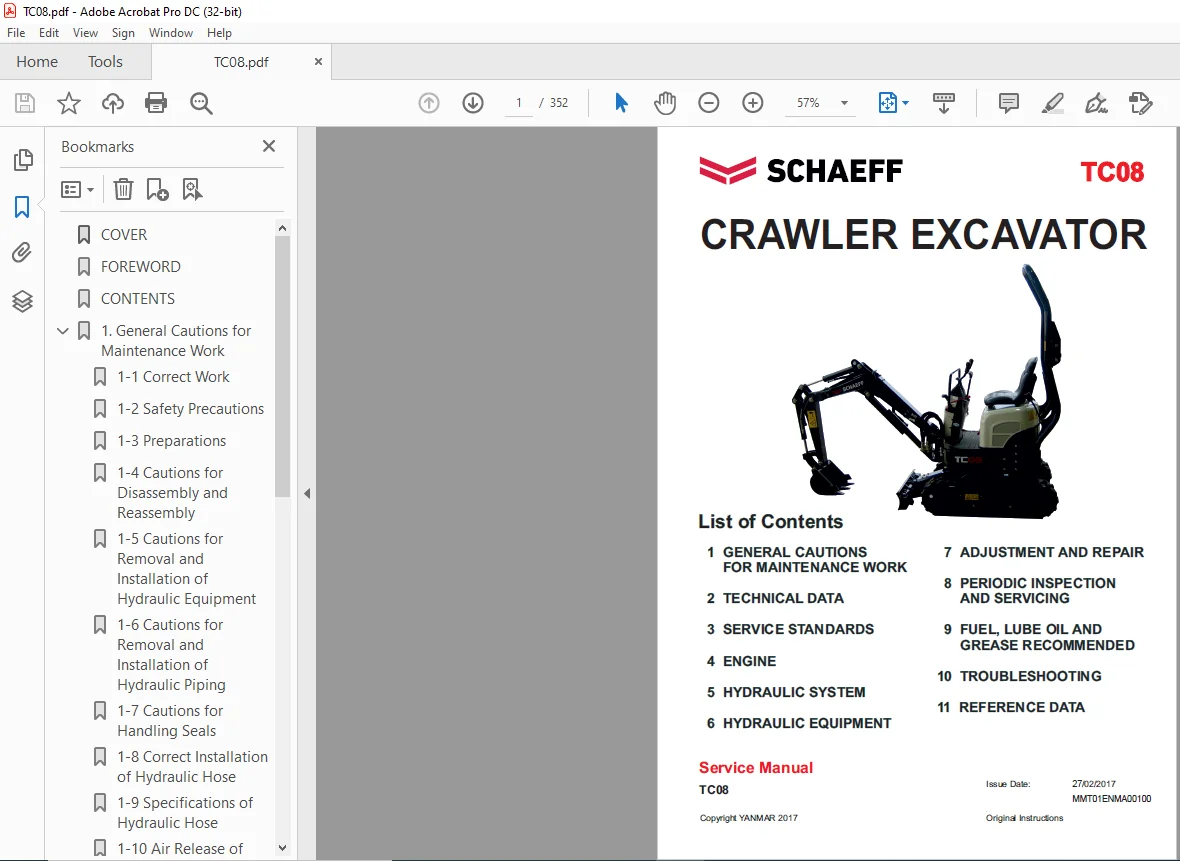
SCHAEFF TC08 CRAWLER EXCAVATOR SERVICE MANUAL – PDF DOWNLOAD
SCHAEFF TC08 CRAWLER EXCAVATOR SERVICE MANUAL – PDF DOWNLOAD:
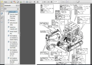
IMAGE PREVIEW:
SCHAEFF TC08 CRAWLER EXCAVATOR SERVICE MANUAL – PDF DOWNLOADSCHAEFF TC08 CRAWLER EXCAVATOR SERVICE MANUAL – PDF DOWNLOAD
DESCRIPTION:
SCHAEFF TC08 CRAWLER EXCAVATOR SERVICE MANUAL – PDF DOWNLOAD
Correct work means the quickest possible completion of according to the correct procedures and the specified standards.
It is important when conducting certain operations always to bear in mind the equipment, tools, gauges, materials, oil and grease, etc. that you must have ready, as well as items to be checked, adjusted, or disassembled, and cautions to watch out for.
(1) Never attempt servicing while engine is running or immediately after stopping operation. (2) Wear work cloths, safety shoes and helmet. (3) Check the equipment and tools before use. Especially, be sure to check the crane, lifting equipment and tools.
(4) When working together with other persons, allocate everyone’s share of job, arrange the signals and act in concert with the other persons. (5) The operation of the crane and slinging work must be performed by qualified persons.
(6) Do not enter or pass under the raised load. (7) Lift and support the massive parts by crane before removing the installation bolts. (8) Disconnect cables from battery before repairing the electric system.
(9) Remove the battery when welding the machine. (1) Check the service record of the machine. (That is, check how many months or hours the machine has been used since the preceding overhaul, what was the trouble then and what parts were replaced.)
(2) Have all servicing tools ready, i.e., tools, measuring devices (which have received periodic maintenance), containers, oil & grease, etc. (3) Have the service literature (operation manual, parts catalog, etc.) ready.
(1) Clean the machine before disassembly. (2) Check and record the condition of the machine before disassembly : • Model, machine number, operation hours • Reasons for repair, history of repair •
Contamination of filters • Fuel and oil condition • Damage to parts, etc. (3) Place alignment marks on the necessary parts to facilitate reassembly. (4) Clean all the removed parts and new replacement parts and put them in order. (5) Use new seals, split pins, etc. for reassembly.
TABLE OF CONTENTS:
SCHAEFF TC08 CRAWLER EXCAVATOR SERVICE MANUAL – PDF DOWNLOAD
COVER
..................................................................................... 1
FOREWORD................................................................................... 3
CONTENTS................................................................................... 4
1. General Cautions for Maintenance Work................................................... 11
1-1 Correct Work....................................................................... 11
1-2 Safety Precautions................................................................. 11
1-3 Preparations....................................................................... 11
1-4 Cautions for Disassembly and Reassembly............................................ 11
1-5 Cautions for Removal and Installation of Hydraulic Equipment....................... 12
1-6 Cautions for Removal and Installation of Hydraulic Piping.......................... 12
1-7 Cautions for Handling Seals........................................................ 13
1-8 Correct Installation of Hydraulic Hose............................................. 13
1-9 Specifications of Hydraulic Hose................................................... 16
1-10 Air Release of Hydraulic Equipment................................................ 21
2. Technical Data.......................................................................... 25
2-1 Specifications..................................................................... 25
2-2 Outline Drawing and Working Area................................................... 33
2-3 Weight List of Main Parts.......................................................... 34
2-4 Lifting Capacity List.............................................................. 35
3. Service Standards....................................................................... 39
3-1 Machine Performance................................................................ 39
3-2 Engine............................................................................. 43
3-3 Undercarriage...................................................................... 47
3-3-1 Rubber Crawler Specifications................................................ 47
3-4 Controls........................................................................... 49
3-5 Hydraulic Equipment................................................................ 50
3-5-1 Hydraulic Cylinders.......................................................... 50
3-6 Implement.......................................................................... 51
3-6-1 Front Attachments............................................................ 51
3-6-2 Blade Moving Device.......................................................... 52
3-6-3 Bucket Teeth................................................................. 52
3-6-4 Variable Track Gauge Type.................................................... 53
3-7 List of Tightening Torque.......................................................... 54
3-7-1 Machine...................................................................... 54
3-7-2 Engine....................................................................... 57
3-7-3 Tightening Torque for General Bolts and Nuts (Machine)....................... 58
3-7-4 Hydraulic Hose Joint......................................................... 59
4. Engine.................................................................................. 63
4-1 Disassembly of Engine.............................................................. 63
4-1-1 Removing the Nozzle and Glow Plug............................................ 63
4-1-2 Removing the Cylinder Head Cover............................................. 63
4-1-3 Removing the Oil Pipe........................................................ 63
4-1-4 Removing the Water Pump Assembly............................................. 63
4-1-5 Removing the Rocker Arm and Push Rods........................................ 64
4-1-6 Removing the Exhaust Manifold................................................ 64
4-1-7 Removing the Cylinder Head................................................... 65
4-1-8 Removing the Tappets......................................................... 65
4-1-9 Removing the Injection Pump Assembly......................................... 65
4-2 Disassembly, Inspection and Reassembly of Main Component Parts..................... 70
4-2-1 Cylinder Head................................................................ 70
4-2-2 Rocker Arm................................................................... 72
4-2-3 Cylinder Block............................................................... 73
4-2-4 Piston and Piston Rings...................................................... 74
4-2-5 Connecting Rod............................................................... 76
4-2-6 Connecting Rod Metal......................................................... 77
4-2-7 Bearing Holder............................................................... 78
4-2-8 Crankshaft Bearing........................................................... 79
4-2-9 Crankshaft................................................................... 79
4-3 Reassembly of Engine............................................................... 85
4-3-1 Crankshaft and Bearing Holder Assembly....................................... 85
4-3-2 Oil Seal and Flywheel Cover (Rear Plate)..................................... 85
4-3-3 Flywheel..................................................................... 85
4-3-4 Pistons and Connecting Rods.................................................. 86
4-3-5 Suction Pipe and Suction Filter.............................................. 86
4-3-6 Oil Pan and Front Plate...................................................... 87
4-3-7 Camshaft Assembly and Plate.................................................. 87
4-3-8 Idle Gear and Oil Pump Assembly.............................................. 87
4-3-9 Timing Gear Case............................................................. 88
4-3-10 Crankshaft Pulley........................................................... 89
4-3-11 Injection Pump Assembly..................................................... 89
4-3-12 Oil filter and Oil Pipe..................................................... 91
4-3-13 Tappets..................................................................... 91
4-3-14 Cylinder Head Assembly and Cylinder Head Gasket............................. 91
4-3-15 Caps, Push Rods and Rocker Arm Assembly..................................... 92
4-3-16 Adjusting the valve clearance............................................... 93
4-3-17 Cylinder Head Cover......................................................... 93
4-3-18 Water Pump Assembly......................................................... 93
4-3-19 Oil Pressure Switch......................................................... 93
4-3-20 Nozzle and Holder Assembly.................................................. 94
4-3-21 Return Pipes and Injection Pipes............................................ 94
4-3-22 V-belt...................................................................... 94
4-4 Electrical Equipment............................................................... 95
4-4-1 Starter Motor................................................................ 95
4-4-2 Alternator...................................................................100
4-4-3 Glow Plug....................................................................102
4-4-4 Stop Solenoid................................................................102
4-5 Troubleshooting....................................................................103
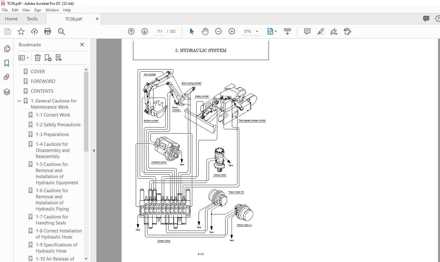
5. Hydraulic System........................................................................107
5-1 Outline............................................................................107
5-1-1 Control Valve Operation......................................................110
5-2 Hydraulic Circuit Schematic........................................................112
5-3 Circuit Operation..................................................................113
5-3-1 Boom.........................................................................113
5-3-2 Arm..........................................................................115
5-3-3 Bucket.......................................................................117
5-3-4 Swing........................................................................119
5-3-5 Boom Swing...................................................................121
5-3-6 Blade........................................................................123
5-3-7 Travel.......................................................................125
5-3-8 Simultaneous Operation of Travel and Blade...................................127
5-3-9 Hydraulic P.T.O..............................................................129
5-3-10 Simultaneous Operation of Boom Up and Bucket................................131
5-3-11 Track Gauge Change..........................................................133
5-4 Pressure Adjustment................................................................135
5-4-1 Relief Valves................................................................135
5-4-2 Swing Combination Valve (Brake Valve)........................................137
6. Hydraulic Equipment.....................................................................141
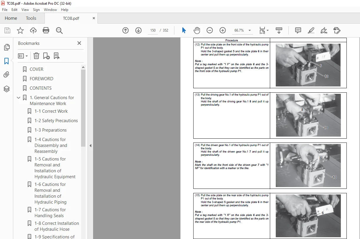
6-1 Hydraulic Pump.....................................................................141
6-2 Control Valve......................................................................161
6-3 Swing motor........................................................................181
6-4 Valve Block........................................................................199
6-5 Travel Motor.......................................................................206
7. Adjustment and Repair...................................................................235
7-1 Electrical Equipment of Machine....................................................235
7-1-1 Parts Layout of Electrical Equipment.........................................235
7-1-2 Monitor and Alarm Systems....................................................236
7-1-3 Wiring Diagram...............................................................239
7-1-4 Circuit Description of Engine Start and Stop.................................240
7-1-5 Circuit Description of Battery Charging......................................241
7-1-6 Removal and Reinstallation of Engine.........................................243
7-1-7 Removal and Reinstallation of Starter motor..................................248
7-2 Undercarriage......................................................................250
7-2-1 Outline......................................................................250
7-2-2 Points of Reassembly.........................................................251
7-2-3 Disassembly and Reassembly of Idler..........................................252
7-2-4 Disassembly and Reassembly of Track Roller...................................254
7-3 Controls...........................................................................256
7-3-1 Control Train................................................................256
7-3-2 Removal and Reinstallation of Control Levers.................................257
7-3-3 Adjustment of Control Levers.................................................260
7-3-4 Adjustment of Travel Levers..................................................261
7-3-5 Adjustment of P.T.O. Pedal...................................................262
7-3-6 Adjustment of Boom Swing Pedal...............................................262
7-3-7 Adjustment of Blade Lever....................................................263
7-3-8 Adjustment of Accelerator Lever (Adjustment of Engine Idling Speed)..........264
7-4 Swing Bearing......................................................................265
7-4-1 Removal and Reinstallation of Swing Bearing..................................265
7-5 Hydraulic Equipment................................................................268
7-5-1 Removal and Reinstallation of Hydraulic Pump.................................268
7-5-2 Removal and Reinstallation of Control Valve..................................270
7-5-3 Removal and Reinstallation of Swing Motor....................................273
7-5-4 Removal and Reinstallation of Swivel Joint...................................275
7-5-5 Disassembly and Reassembly of Swivel Joint...................................280
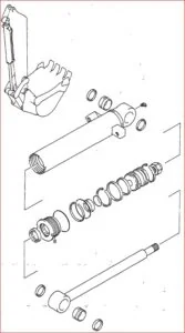
7-5-6 Disassembly and Reassembly of Hydraulic Cylinders............................283
7-5-7 Removal and Reinstallation of Hydraulic Oil Tank.............................287
7-5-8 Piping Layout................................................................289
7-6 ROPS Bar...........................................................................295
7-6-1 Removal and Reinstallation of ROPS bar.......................................295
7-7 Work Implements....................................................................299
7-7-1 Removal and Reinstallation of Work Implements................................299
8. Periodic Inspection and Servicing.......................................................311
8-1 List of Periodic Inspection and Servicing..........................................311
9. Fuel, Lube Oil and Grease Recommended...................................................315
10. Troubleshooting........................................................................319
10-1 Non-Breakdowns....................................................................319
10-1-1 Natural Release of Bucket...................................................319
10-1-2 Discontinuous Arm Movement..................................................319
10-1-3 Drifting of Upperstructure on Quick Travel Operation........................320
10-1-4 Thermal Shock of Travel Motor...............................................321
10-1-5 Fluctuation in Oil Level of Hydraulic Oil Tank Due to Temperature Change....322
10-2 Troubleshooting...................................................................323
10-2-1 Machine and Engine..........................................................323
10-2-2 Electrical Equipment on Panel...............................................342
11. Reference Data.........................................................................351
11-1 Dimensions and Specifications for Attachment......................................351
PLEASE NOTE:
This is the same manual used by the dealers to diagnose and troubleshoot your vehicle
You will be directed to the download page as soon as the purchase is completed. The whole payment and downloading process will take anywhere between 2-5 minutes
Need any other service / repair / parts manual, please feel free to contact [email protected] . We still have 50,000 manuals unlisted
SK
1 review for SCHAEFF TC08 CRAWLER EXCAVATOR SERVICE MANUAL – PDF DOWNLOAD
5 out of 5
Jett Braden –
I had a hard time finding the manual until i googled the information, and found your website!


Jett Braden –
I had a hard time finding the manual until i googled the information, and found your website!