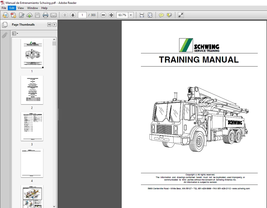
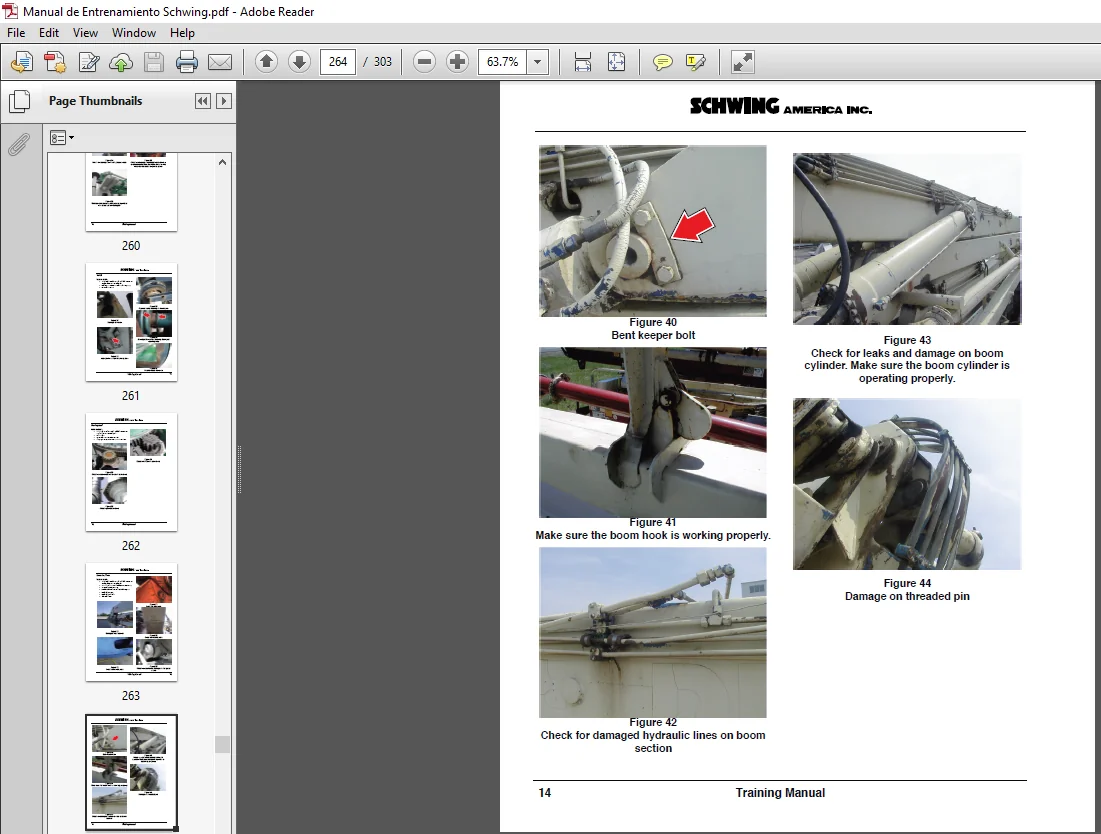
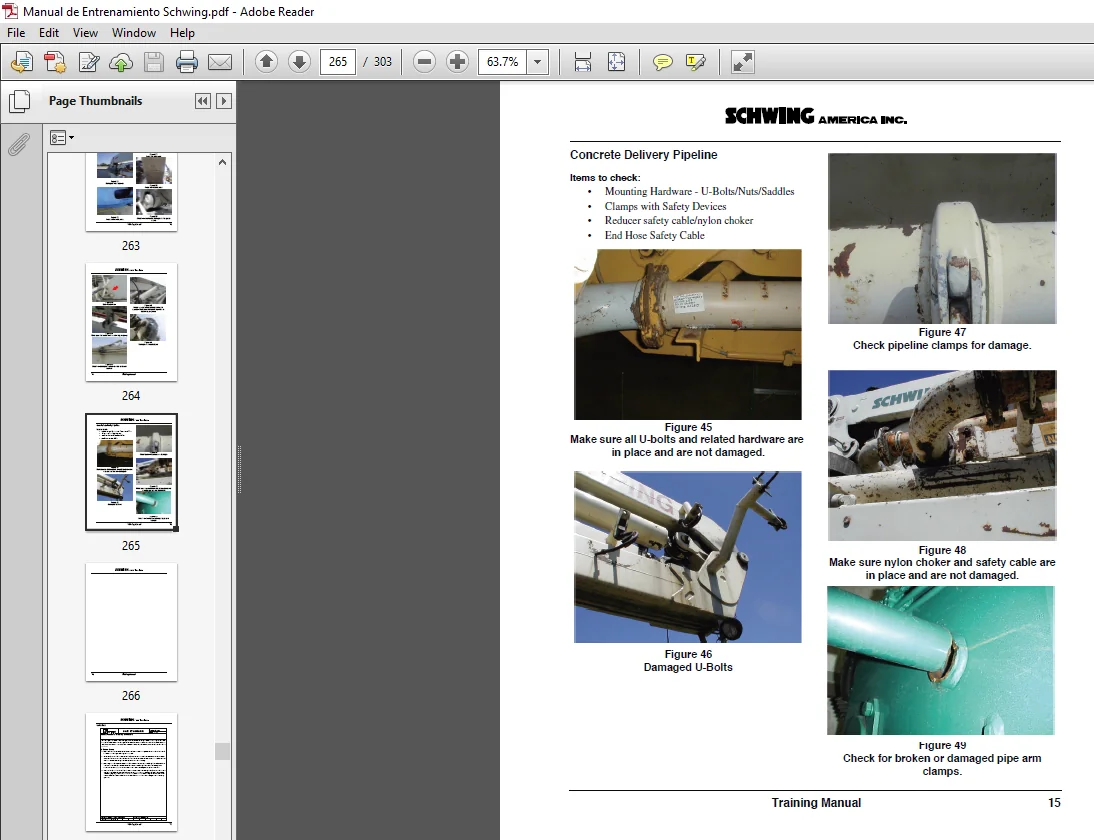
Schwing Concrete Pump Service Training Manual – Heavy Equipment Hydraulic, Electrical & Mechanical Workshop Guide
Original price was: $150.00.$34.95Current price is: $34.95.
Master the maintenance, diagnostic troubleshooting, and hydraulic rebuilding of Schwing truck-mounted concrete pumps with this comprehensive, factory-level technical training service manual. Covering both Single-Circuit and Twin-Circuit configurations (including MPS, Soft-Switch, and Hi-Flow architectures), load-sensing placing booms, Rexroth hydraulic pumps (A11VO, A7VO, A10VO), Vector and CPC electronic control systems, and field calibration procedures, this exhaustive field reference is an essential manual for certified heavy equipment mechanics, fleet technicians, and concrete pump operators.
Description
SCHWING SERVICE TRAINING MANUAL – PDF DOWNLOAD
Image Preview:
Table Of Contents:
Schwing Service Training Manual
Description:
Schwing Service Training Manual
Engineered directly from Schwing America’s technical instruction division, this Schwing Service Training Manual delivers in-depth mechanical, hydraulic, and electrical knowledge required to commission, calibrate, inspect, and overhaul modern concrete pumping equipment.
Concrete pumps operate under extreme hydraulic pressures exceeding 350 bar while dynamically transferring abrasive concrete slurries through complex boom pipelines. This workshop guide breaks down each sub-assembly into easy-to-follow flow schematics, mechanical cross-sections, DIN/ANSI hydraulic symbology, and step-by-step diagnostic procedures. From foundational hydraulic laws and transfer-case power flow to fine-tuning variable-displacement swashplates and tracking electrical faults across solid-state digital nodes, this manual provides complete operational mastery.
Key Modules & Systems Covered
1. Power Take-Off (PTO) & Mechanical Drivetrain
Pneumatic Interlocks: Cab-mounted PTO air switch operation, spool-air routing, and pressure switch verification.
Distribution Transfer Cases: Internal mechanical operation of Stiebel 4194, 4195, and 4400 split-shaft gearboxes, directing truck engine power between road travel and pump-drive modes.
Continuous Duty Solenoids: 12V continuous engagement circuitry interfacing the air switch with secondary pump and controller systems.
2. Hydraulic Pump Architecture & Regulation
Main Hydraulic Pumps: Bent-axis and swashplate variable-displacement axial piston pumps (Rexroth A11VO-130/190, A7VO, A10VO) and fixed-displacement gear/piston units (A2F20).
Horsepower Limiting (Constant Power Control): Load-limiting functionality preventing engine stall under high pumping pressures by automatically backing off displacement when system thresholds are reached.
Mechanical Adjustments: Field setting instructions for minimum displacement ($Q_{\min}$), maximum displacement ($Q_{\max}$), beginning of stroke regulation (8–10 bar), and pressure cut-off valves.
3. Concrete Pumpkit Configurations & Phase Cycles
Gate Valve Systems: Deep dives into legacy 800 and 801 gate valve pumpkits with differential cylinder stroke-signal grooves and needle valves.
Single-Circuit Rock Valve Systems: Detailed Phase A through Phase K operational sequences covering S1, S2, and S3 valve shifting, material cylinder alternate stroke cycles, and loop oil crossover mechanics.
Twin-Circuit Systems: Dedicated independent accumulator circuits for high-speed Rock Valve switching isolated from main differential cylinder movement.
Hi-Flow G-3 Generation Blocks: Advanced integrated main control blocks designed for flow rates up to 800 LPM, integrating main flow poppets, pilot soft-switch reversing valves, and high-flow differential control.
MPS (Manifolded Pilot Switching): Triple-directional NG 6 control valve operations replacing mechanical proximity cylinder switching for rapid, reliable Rock Valve slewing.
4. Placing Boom & Outrigger Hydraulic Circuits
Load-Sensing Proportional Controls: Differential pressure ($\Delta P$) regulation, section compensators, and variable displacement delivery matching dynamic boom loads.
Valving & Control Manifolds: Apitech directional handvalves with PWM-driven pulsar coils, pilot pressure supplies, emergency stop dump blocks, and manual bypass sequences.
Safety Holding Valves (HER / H.E.R.): Hydraulically unlockable dual-check counterbalance holding valves mounted directly on boom section cylinders to eliminate drift and uncontrolled descent.
5. Electronic & Digital Controller Platforms
Supported Controller Suites: Analog systems, Digi-Prop, Comfort Control, C32, CPC, CPC II, and modern digital Vector controllers.
CAN-Bus & Digital Transformation: Signal conversion from analog operator inputs to digital command words (0s and 1s) and back to proportional PWM valve currents.
Wiring Schematics: Full ladder logic and DIN-standard schematics, including dedicated 28X truck, boom, and pumpkit junction box interconnects.
Step-by-Step Field Calibration & Workshop Procedures
Material Cylinder Alignment: Complete waterbox light-ray inspection procedure using specialized centering tools to verify parallel barrel alignment without damaging cylinder walls or rubber rams.
Rod-Side to Piston-Side Conversion: Hose re-routing and crossover procedures to transform a pumpkit from high-volume/standard-pressure to high-pressure/low-volume mode.
Differential Cylinder Shimming: Mathematical measurement and formula guide ($B – A = \text{shims required}$) using chevron seal stack compaction to safeguard cylinder rods against seal swelling.
Apitech Control Chamber Bleeding: Air-bleeding protocols for PC1 and PC2 end chambers across various manifold orientations (standard horizontal, inverted solenoids, vertical).
Main Relief & Soft Switch Pressure Setting: Operational sequence to warm hydraulic oil to 50°C using agitator bypass before setting the 350-bar main system relief and the 80-bar soft-switch poppet limits.
Pump Performance Validation & Nomographs: Using flowmeters, horsepower curves, and multi-quadrant job nomographs to calculate Power Factor (PF) requirements, pipeline friction values, and pump volumetric efficiency.
Product Specifications
| Attribute | Specification Details |
| Product Type | Heavy Equipment Workshop Service & Training Manual |
| Manufacturer Coverage | Schwing America, Inc. / Schwing Group |
| Language | English |
| Format | Searchable PDF / Print-Ready Digital Document |
| Page Count | ~220 Pages (Exhaustive Technical Content) |
| Schematics Included | Full Hydraulic Schematics (DIN/ISO), Electrical Schematics, Ladder Logic |
| Applicable Pumpkits | 800, 801, 900, 1200 Single Circuit, 1200 Twin Circuit, 2020, 2023, 2525, 2525H Hi-Flow |
| Pump / Valve Brands Covered | Rexroth (A11VO, A7VO, A10VO, A2F), Stiebel, Apitech, Monsun-Tison, Sauer |
| Target Equipment | Truck-Mounted Concrete Pumps & Placing Booms (e.g., KVM 28, S 28X, S 36X, S 42, S 52, S 58 SX) |
Please Note:
- This is the SAME exact manual used by your dealers to fix your vehicle.
- The same can be yours in the next 2-3 mins as you will be directed to the download page immediately after paying for the manual.
- Any queries / doubts regarding your purchase, please feel free to contact [email protected]