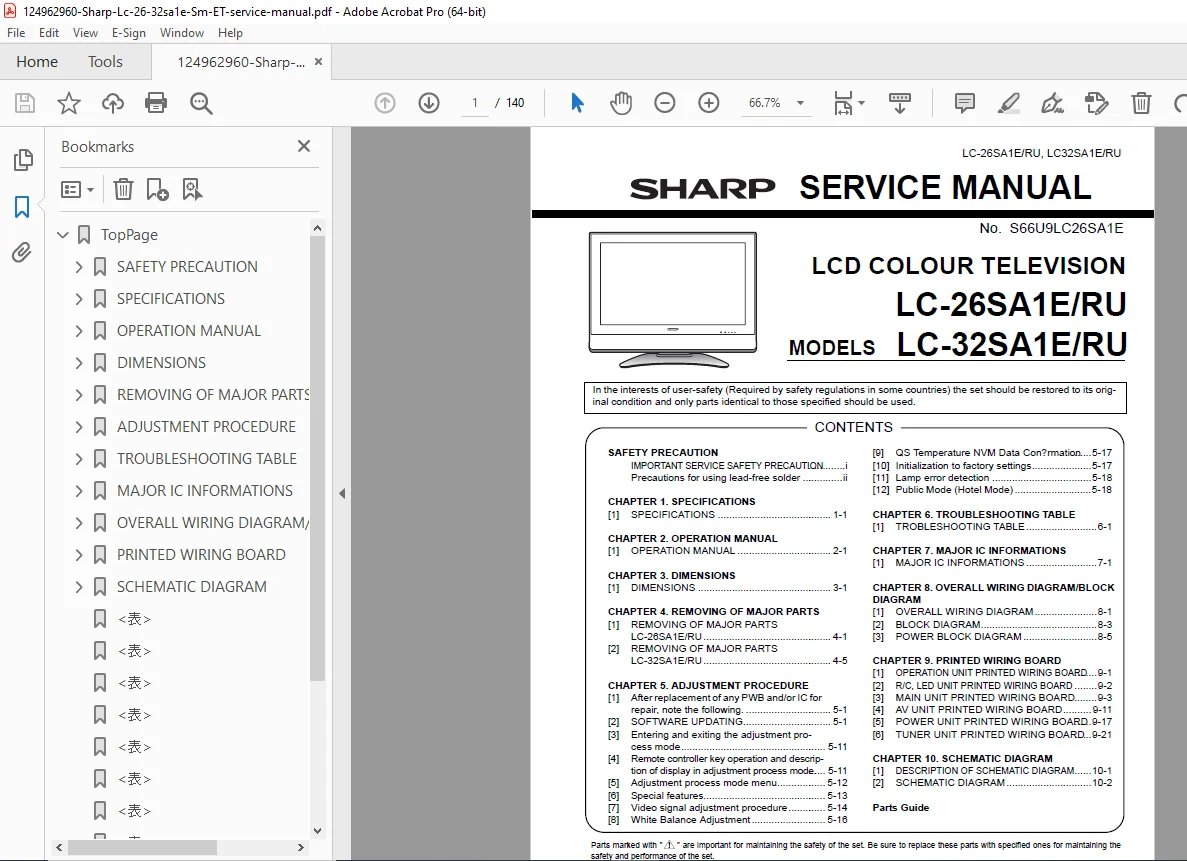
Sharp LC-26SA1E / LC-32SA1E LCD Television Service Manual – PDF
Original price was: $75.00.$15.95Current price is: $15.95.
Comprehensive Sharp LC-26SA1E and LC-32SA1E LCD television service manual for qualified technicians. Complete technical documentation covering LCD color television specifications, disassembly procedures, component replacement, troubleshooting, electrical schematics, block diagrams, printed wiring board layouts, adjustment procedures, calibration guidelines, and lead-free solder repair techniques. Professional repair documentation for 26-inch and 32-inch LCD TV models with complete parts lists.
Description
Sharp LC-26SA1E / LC-32SA1E LCD Television Service Manual & Repair Guide - PDF DOWNLOAD
DESCRIPTION
Sharp LC-26SA1E / LC-32SA1E LCD Television – Complete Service Manual
This comprehensive 140-page professional service manual is the definitive technical resource for qualified service technicians repairing Sharp LC-26SA1E and LC-32SA1E LCD color television models. This advanced flat-screen television documentation covers all aspects of maintenance, diagnostics, repair, and component-level troubleshooting for both 26-inch and 32-inch LCD TV variants with regional specifications.
Complete Manual Contents & Coverage:
- Safety Precautions & Important Information – Detailed safety warnings for qualified service personnel, leakage current testing procedures (1.5kΩ, 10W resistor configuration with 0.15µF capacitor), before-returning safety checks, electrical shock hazard prevention, fire hazard guidelines, and fuse replacement specifications (F701 4A/250V)
- Lead-Free Solder Technology – Comprehensive instructions for lead-free solder (Sn-Ag-Cu) with 220°C melting point (40°C higher than conventional solder), soldering bit temperature control specifications (370±10°C), wetting characteristics guidance, tip oxidation prevention procedures, and lead-free wire solder part numbers with detailed specifications
- Full Technical Specifications – Complete device specifications including display technology, resolution, power consumption, dimensions, weight specifications for both 26″ and 32″ models, operating temperature/humidity ranges, and performance characteristics
- Complete LCD Television Components – Detailed identification of all major systems:
- LCD Panel Units (26″ and 32″ panel specifications)
- Backlight and LED systems
- Audio subsystems (Speaker L/R with specific part codes)
- Video processing circuits
- Tuner units with terrestrial/cable specifications
- RF (radio frequency) antenna systems
- Disassembly & Reassembly Procedures – Step-by-step procedures for both models:
- Stand and base removal with specific screw counts and locations
- Rear cabinet disassembly procedures
- Bottom cover and protective cover removal
- Top control cover assembly procedures
- Center angle and stand angle removal
- Power supply unit extraction
- Tuner unit disassembly with earth plate specifications
- Main unit removal procedures
- AV input/output unit disassembly
- Chassis tray separation
- R/C (remote control) and LED unit removal
- Speaker system disassembly (both L and R channels)
- LCD panel angle removal procedures
- Front cabinet separation and LCD panel extraction
- Complete Wiring Documentation – Comprehensive connector identification and specifications:
- P201, P301, P703, P701, P702, P704 connector pinouts
- KM connector specifications with detailed connections
- SC connectors (SC301, SC2702, SC2703, SC2704, SC2705)
- RA (Remote control) connector specifications
- LA (LCD panel) connector pinouts
- SH, LV connector documentation
- Complete connector labeling and routing diagrams
- Printed Wiring Board Documentation – Detailed PCB layouts for:
- Operation Unit PCB with component identification
- R/C (Remote Control) and LED Unit PCB schematics
- Main Unit PCB with multiple pages of component layout
- AV Unit PCB with input/output component placement
- Power Supply Unit PCB with power circuitry
- Tuner Unit PCB with RF and IF circuits
- Component marking and reference designators
- Electrical Schematics & Block Diagrams – Complete technical documentation:
- Overall wiring diagram with all interconnections
- System block diagram showing signal flow
- Power block diagram with power distribution
- Detailed schematic diagrams with component values
- Power supply specifications and protection circuits
- Video signal processing circuits
- Audio amplifier circuits
- Tuner/RF circuits with IF specifications
- Adjustment Procedures – Comprehensive calibration and adjustment guidelines:
- PWB (Printed Wiring Board) replacement procedures
- Software updating protocols
- Adjustment mode entry/exit procedures
- Remote controller operation in service mode
- Adjustment process mode menu navigation
- Special features configuration
- Video signal adjustment procedures with reference patterns
- White balance adjustment specifications
- QS (temperature) NVM data confirmation procedures
- Factory settings initialization
- Lamp error detection diagnostics
- Public Mode (Hotel Mode) configuration
- Troubleshooting Documentation – Systematic troubleshooting guide:
- Comprehensive troubleshooting table with symptoms and solutions
- Common failure modes and corrective actions
- Power supply troubleshooting procedures
- Video signal problems diagnosis
- Audio system troubleshooting
- Display issues (dead pixels, backlight problems)
- Remote control malfunction diagnosis
- Tuner reception problems
- HDMI connection issues
- Major IC (Integrated Circuit) Information – Detailed specifications for:
- Primary processing ICs with pinout diagrams
- Memory devices (Flash, EEPROM, DRAM specifications)
- Power management ICs
- Video processing chips
- Audio codec specifications
- Tuner IC documentation
- Driver IC specifications
- Complete datasheet references
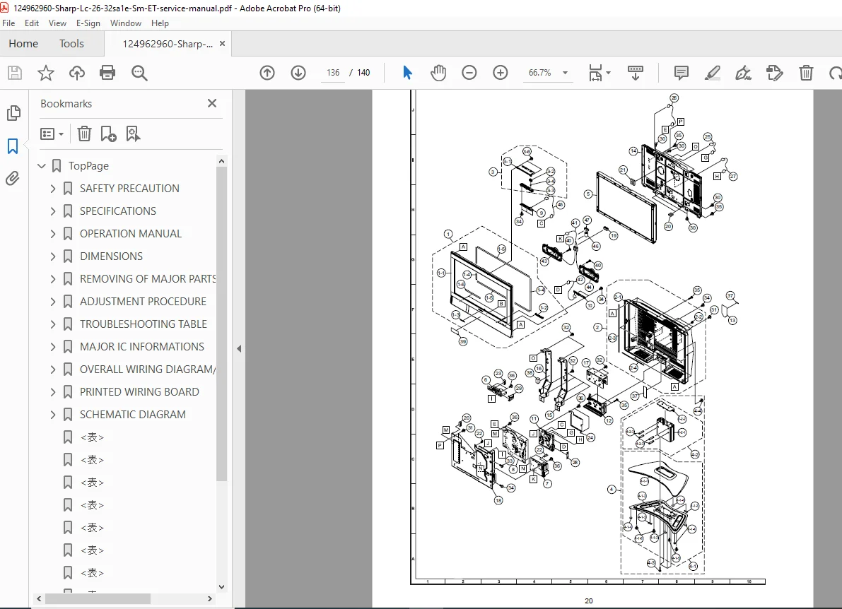
- Comprehensive Parts Lists – Detailed component identification:
- Cabinet parts with complete part codes for both models
- Front cabinet assembly parts (LED covers, badges, spacers, cushions)
- Rear cabinet components
- Top control cover components with button specifications
- Stand assembly parts with base covers and angles
- Leg cushions and support structures
- LCD angle brackets and mounting hardware
- Center angles (left and right) for 32″ model
- Tuner unit components
- AV input/output unit parts
- Power supply components
- Operation unit parts
- R/C and LED unit components
- Speaker specifications and part codes
- Chassis tray components
- Wire holders and cable management components
- Shield and absorption components
- Connecting cord specifications
- Earth plates and grounding components
- Fastener specifications (screws with exact sizes and quantities)
- Supplied Accessories & Optional Parts – Documentation of:
- Remote control unit (RRMCGA531WJSA)
- AC power cord variants (Europe without UK, UK-specific)
- 3 RCA to 15-pin D-sub adapter
- Cable ties and cable clamps
- Packaging materials
- Operating manuals in multiple languages (English, Swedish, Polish, Russian)
- Stand assembly options
- Care plan information
- Warranty cards
- Packing Information – Specifications for:
- Packing case variants for different models
- Buffer material specifications
- Wrapping paper types
- Case labeling and identification
- Protective packaging procedures
- Service Jigs & Extension Cables – Technical support documentation for:
- 23-pin board-to-board extension cables
- 9-pin board-to-board extension cables
- 15-pin board-to-board extension cables
- 7-pin board-to-board extension cables
- Interface cables with specific pin configurations
- D-sub and Mini DIN connectors
- Dimensions & Physical Specifications – Complete technical drawings showing:
- Overall cabinet dimensions for both 26″ and 32″ models
- Height measurements including stand
- Depth specifications
- Width dimensions
- Component placement locations
- Mounting bracket specifications
Document Quality: Professional 140-page PDF (originally created September 2006, last updated 2009) with Adobe Illustrator and Acrobat Distiller, containing detailed component diagrams, exploded views, electrical schematics, block diagrams, and complete service documentation from Sharp Corporation.
FILE DETAILS TABLE
| Detail | Information |
|---|---|
| Manual Name | Sharp LC-26SA1E / LC-32SA1E LCD Television Service Manual |
| Models Covered | LC-26SA1E/RU, LC-32SA1E/RU (Regional variants: /F, /I, /K) |
| Device Type | LCD Flat-Screen Color Television |
| Screen Sizes | 26-inch and 32-inch display options |
| Year Published | 2006 |
| Last Updated | 2009 |
| Total Pages | 140 pages |
| PDF Quality | High Resolution (Professional Grade) |
| Document Type | Service & Repair Manual |
| File Size | 31 MB (Large format with detailed diagrams) |
| Language | English (with multi-language support documentation) |
| Target Users | Qualified Service Technicians & Repair Engineers |
| Technology | Lead-Free Solder PCBs with Sn-Ag-Cu specification |
| Manual Number | S66U9LC26SA1E |