Shimadzu GC-2014 Service Manual – PDF DOWNLOAD
Original price was: $65.00.$14.95Current price is: $14.95.
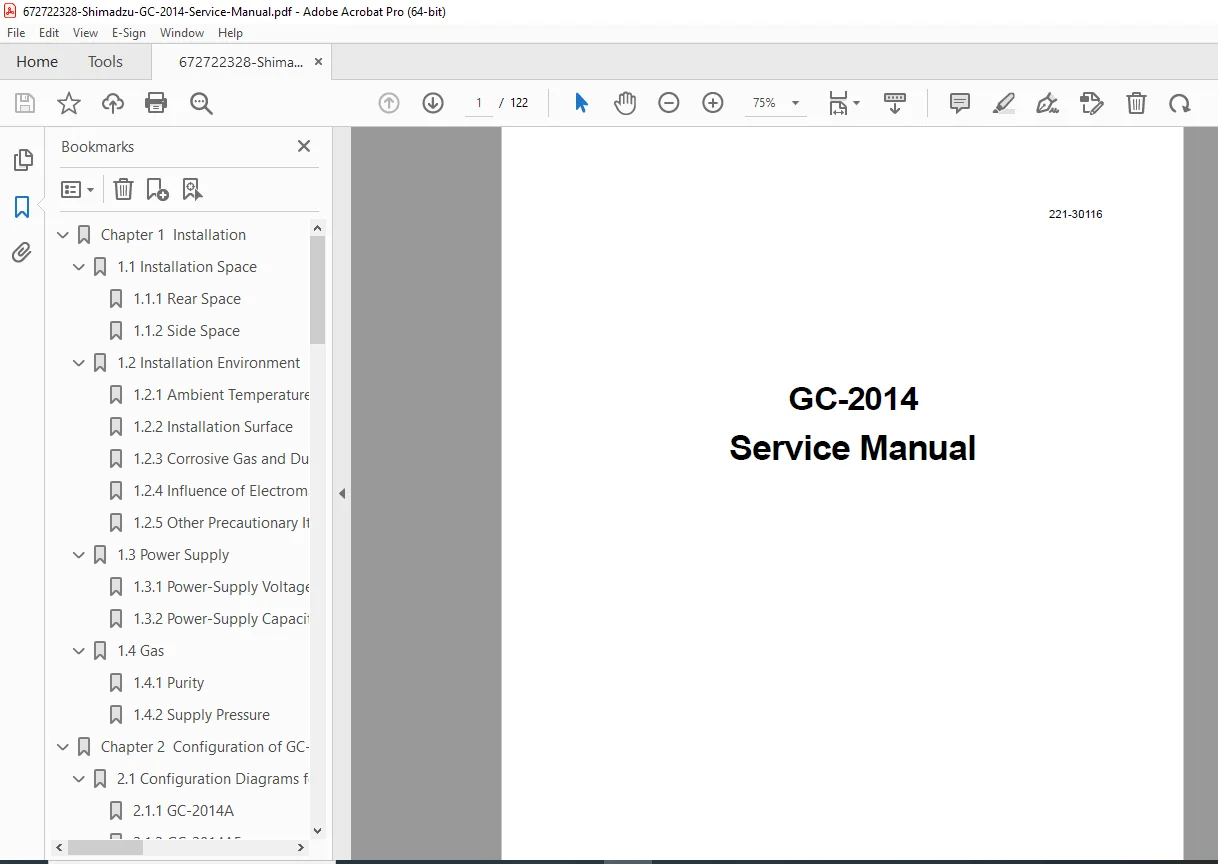
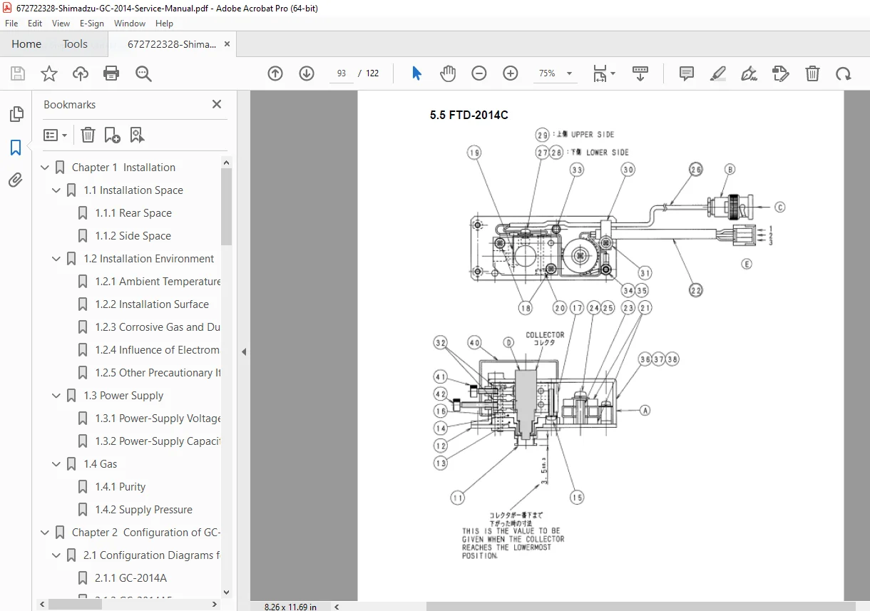
Official Shimadzu GC-2014 service manual for gas chromatograph systems (Document 221-30116, May 2005, Author: Y. Fuse). This comprehensive 122-page technical manual covers installation requirements, system configuration (GC-2014A/AF/AFsc/AFSPL/AT/ATF/ATFSPL), structure diagrams, electric circuits, CPU/power unit schematics, TCD/FID detector service, oven temperature control, injector maintenance, detector troubleshooting, calibration procedures, and complete service information for qualified analytical instrument technicians servicing laboratory gas chromatography systems.
Description
Shimadzu GC-2014 Service Manual Gas Chromatograph Repair Maintenance – PDF DOWNLOAD
DESCRIPTION
This is the official Shimadzu GC-2014 Service Manual (Document Number 221-30116, Copyright © 2005 Shimadzu Corporation) for the GC-2014 series gas chromatograph. This comprehensive 122-page technical manual is intended for use by Shimadzu-approved service engineers and provides complete maintenance, troubleshooting, calibration, and repair procedures for these advanced analytical instruments used in chemical analysis, environmental testing, pharmaceutical quality control, and research laboratories worldwide.
Product Overview
Shimadzu GC-2014 Gas Chromatograph:
The GC-2014 represents Shimadzu’s advanced gas chromatograph platform designed for routine and demanding analytical applications. This sophisticated instrument combines precision temperature control, multiple detector options (FID, TCD), advanced electronic control, and comprehensive analytical capabilities to deliver accurate and reliable gas chromatographic analysis for diverse laboratory applications.
Key Applications:
- Chemical analysis laboratories
- Environmental testing
- Pharmaceutical quality control
- Petrochemical analysis
- Food and beverage testing
- Forensic laboratories
- Research and development
- Quality assurance/quality control
- Agricultural testing
- Clinical research
Models Covered
GC-2014A:
- Base model gas chromatograph
- Standard configuration
- Single detector capability
GC-2014AF:
- FID (Flame Ionization Detector) configuration
- Standard analytical applications
GC-2014AFsc:
- FID configuration with split/splitless injector
- Enhanced sample introduction
GC-2014AFSPL:
- FID with advanced split/splitless capability
- Specialized injection modes
GC-2014AT:
- TCD (Thermal Conductivity Detector) configuration
- Universal detection capability
GC-2014ATF:
- Dual detector (TCD + FID)
- Versatile analytical capability
GC-2014ATFSPL:
- Dual detector with advanced injector
- Complete analytical platform
Key Technical Systems
Oven System:
- Precision temperature control
- PT sensor and thermocouple monitoring
- Programmable temperature ramps
- Cooling unit with fan motor
- Temperature range specifications
- Rapid cooling capability
Detector Systems:
FID (Flame Ionization Detector):
- Hydrogen flame detection
- High sensitivity for organic compounds
- Wide linear dynamic range
- Gas flow control
- Ignition system
- Temperature control
TCD (Thermal Conductivity Detector):
- Universal detection
- Non-destructive analysis
- Bridge circuit design
- Temperature control
- Reference and measurement cells
- TCD controller
Injector System:
- Split/splitless injector
- Temperature control
- Septum purge system
- Carrier gas control
- Sample vaporization
Electronic Control:
- CPU unit
- Power unit
- Temperature controllers
- Detector controllers
- Communication interfaces
- Display and control panel
Gas Control:
- Carrier gas control
- Detector gas control
- Pressure regulation
- Flow control
- Gas purity requirements
Comprehensive Manual Contents
DOCUMENT INFORMATION:
- Document Number: 221-30116
- Title: GC-2014 Service Manual
- Subject: Service Manual
- Keywords: 221-xxxxx
- Author: Y. Fuse
- Copyright: © 2005 Shimadzu Corporation
- Manufacturer: Shimadzu Corporation, Analytical & Measuring Instruments Division
- Pages: 122 pages
- Publication Date: May 11, 2005
- PDF Version: 1.3
PRODUCT GUARANTEE AND DISCLAIMER
Product Guarantee:
- Guarantee Period: One year from installation date (Japan only)
- Scope: Repair or part replacement for Shimadzu-attributed faults
- Beyond Scope:
- Incorrect handling
- Unauthorized repairs or modifications
- Factors unrelated to equipment
- Severe environmental conditions
- Fire or natural disasters
- Movement after installation
- Consumable items
Disclaimer:
- Copyright belongs to Shimadzu Corporation
- No unauthorized reproduction permitted
- Contents subject to change for product improvement
- Parts supply period: 7 years after manufacture termination
INTRODUCTION
Manual Purpose:
- For Shimadzu-approved service engineers
- Maintenance methods for GC-2014 series
- Requires specific training
- Supplements instruction manual
- Technical Information updates available
Safety Notation:
- DANGER: Death or serious injury possible
- WARNING: Minor injury or property damage possible
- CAUTION: Product or property damage possible
- NOTE: Operational information and clarification
COMPLETE TABLE OF CONTENTS
CHAPTER 1: INSTALLATION (Pages 5-8)
1.1 Installation Space (Page 5):
1.1.1 Rear Space:
- Required clearance behind instrument
- Service access requirements
- Cable routing space
1.1.2 Side Space:
- Lateral clearance requirements
- Access for maintenance
- Ventilation needs
1.2 Installation Environment (Pages 5-6):
1.2.1 Ambient Temperature and Humidity:
- Operating temperature range
- Storage temperature range
- Humidity specifications
- Environmental control requirements
1.2.2 Installation Surface:
- Level surface requirements
- Load-bearing capacity
- Vibration isolation
- Bench specifications
1.2.3 Corrosive Gas and Dust:
- Environmental restrictions
- Air quality requirements
- Contamination prevention
1.2.4 Influence of Electromagnetic Waves and Power-Supply Noise:
- EMI protection
- Grounding requirements
- Power conditioning
- Interference prevention
1.2.5 Other Precautionary Items:
- Direct sunlight avoidance
- Ventilation requirements
- Safety considerations
1.3 Power Supply (Page 7):
1.3.1 Power-Supply Voltage:
- Voltage specifications
- Frequency requirements
- Voltage tolerance
- Grounding requirements
1.3.2 Power-Supply Capacity:
- Power consumption
- Circuit breaker requirements
- Dedicated circuit recommendations
1.4 Gas (Page 8):
1.4.1 Purity:
- Carrier gas purity specifications
- Detector gas purity requirements
- Contaminant limits
- Gas purification
1.4.2 Supply Pressure:
- Required gas pressures
- Pressure regulation
- Safety limits
CHAPTER 2: CONFIGURATION OF GC-2014 (Pages 9-33)
2.1 Configuration Diagrams for GC-2014 Series (Pages 9-19):
2.1.1 GC-2014A (Page 9):
- Base model configuration
- Component layout
- System diagram
2.1.2 GC-2014AF (Page 10):
- FID configuration
- Detector arrangement
- Gas connections
2.1.3 GC-2014AFsc (Page 11):
- Split/splitless injector configuration
- Component identification
2.1.4 GC-2014AFSPL (Page 11):
- Advanced split configuration
- System layout
2.1.5 GC-2014AT (Page 12):
- TCD configuration
- Component arrangement
2.1.6 GC-2014ATF (Page 13):
- Dual detector (TCD + FID)
- Component layout
- Gas routing
2.1.7 GC-2014ATFSPL (Page 14):
- Complete system configuration
- All components identified
2.2 Structure of GC-2014 (Pages 20-26):
2.2.1 External Appearance (Page 20):
- Front panel
- Control panel
- Display
- Access doors
2.2.2 Structure Diagram 1 (Page 21):
- Internal layout
- Major component locations
- Assembly relationships
2.2.3 Structure Diagram 2 (Page 22):
- Detailed component positions
- Subsystem locations
2.2.4 Structure Diagram 3 (Page 23):
- Additional structural details
- Access points
2.2.5 PT Sensor and Thermocouple (Page 23):
- Temperature sensor types
- Sensor locations
- Specifications
- Wiring
2.2.6 Heater and PT Sensor/Thermocouple (Page 24):
- Heating element locations
- Sensor placement
- Temperature control zones
- Connection diagrams
2.2.7 Fan Motor (Page 24):
- Cooling fan motor specifications
- Motor location
- Replacement procedures
2.2.8 Fan (Page 25):
- Cooling fan specifications
- Airflow patterns
- Maintenance
2.2.9 Structure of Oven Cooling Unit (Page 26):
- Cooling system design
- Component identification
- Operation principles
- Service access
2.3 Electric Circuits (Pages 27-33):
2.3.1 Block Diagram (Page 27):
- System architecture
- Major subsystems
- Signal flow
- Power distribution
2.3.2 CPU Unit (Pages 28-32):
- Microprocessor system
- Memory organization
- I/O interfaces
- Communication ports
- Control algorithms
- Circuit diagrams
2.3.3 Power Unit (Pages 33-36):
- Power supply circuits
- Voltage regulation
- Power distribution
- Protection circuits
- Circuit schematics
2.3.4 TCD Controller (Pages 37-onwards):
- TCD control circuits
- Bridge circuit design
- Temperature control
- Signal conditioning
- Circuit diagrams
REMAINING CHAPTERS (Based on typical Shimadzu GC service manual structure)
CHAPTER 3: MAINTENANCE
- Scheduled maintenance
- Cleaning procedures
- Preventive maintenance
- Inspection intervals
- Consumables replacement
CHAPTER 4: DETECTOR SERVICE
FID Service:
- Flame ignition procedures
- Electrode cleaning
- Jet cleaning
- Gas flow verification
- Sensitivity testing
- Baseline stability
TCD Service:
- Filament inspection
- Cell cleaning
- Bridge balance
- Sensitivity testing
- Temperature verification
CHAPTER 5: INJECTOR SERVICE
- Septum replacement
- Liner cleaning/replacement
- Temperature calibration
- Split ratio verification
- Carrier gas flow testing
CHAPTER 6: OVEN SERVICE
- Temperature calibration
- Sensor testing
- Heater testing
- Cooling system service
- Thermal insulation inspection
CHAPTER 7: GAS CONTROL SYSTEM
- Pressure regulator service
- Flow controller calibration
- Leak testing
- Gas line maintenance
CHAPTER 8: TROUBLESHOOTING
- Systematic diagnostic approach
- Symptom-based troubleshooting
- Error codes
- Performance problems
- Baseline issues
- Peak shape problems
- Sensitivity issues
CHAPTER 9: CALIBRATION AND ADJUSTMENT
- Temperature calibration
- Detector calibration
- Flow calibration
- Pressure calibration
- Electronic calibration
CHAPTER 10: PARTS LIST
- Component part numbers
- Consumables
- Replacement intervals
- Exploded view diagrams
CHAPTER 11: ELECTRICAL SCHEMATICS
- Complete wiring diagrams
- Power circuits
- Control circuits
- Detector circuits
- Communication circuits
Who Needs This Manual?
This Shimadzu GC-2014 service manual is essential for:
- Shimadzu-approved service engineers
- Laboratory instrument technicians (with training)
- Analytical instrument service companies
- University/research facility technical staff
- Quality control laboratory technicians
- Anyone performing authorized service on GC-2014 systems
Prerequisites:
✓ Shimadzu service training certification
✓ Gas chromatography principles knowledge
✓ Electronic troubleshooting skills
✓ Understanding of analytical instrumentation
✓ Proper tools and test equipment
✓ Safety training for gas handling
✓ ESD handling procedures
✓ Detector operation knowledge
FILE DETAILS
| Detail | Specification |
|---|---|
| Document Number | 221-30116 |
| Manual Title | GC-2014 Service Manual |
| Author | Y. Fuse |
| Manufacturer | Shimadzu Corporation, Analytical & Measuring Instruments Division |
| Models Covered | GC-2014A, GC-2014AF, GC-2014AFsc, GC-2014AFSPL, GC-2014AT, GC-2014ATF, GC-2014ATFSPL |
| Publication Date | May 11, 2005 |
| Pages | 122 pages |
| PDF Quality | Professional technical manual with detailed diagrams |
| File Size | 3.6 MB |
| Page Size | A4 (595 x 842 pts) |
| Language | English |
| Creator | Word 用 Acrobat PDFMaker 5.0 |
| Copyright | © 2005 Shimadzu Corporation |
| PDF Version | 1.3 |