
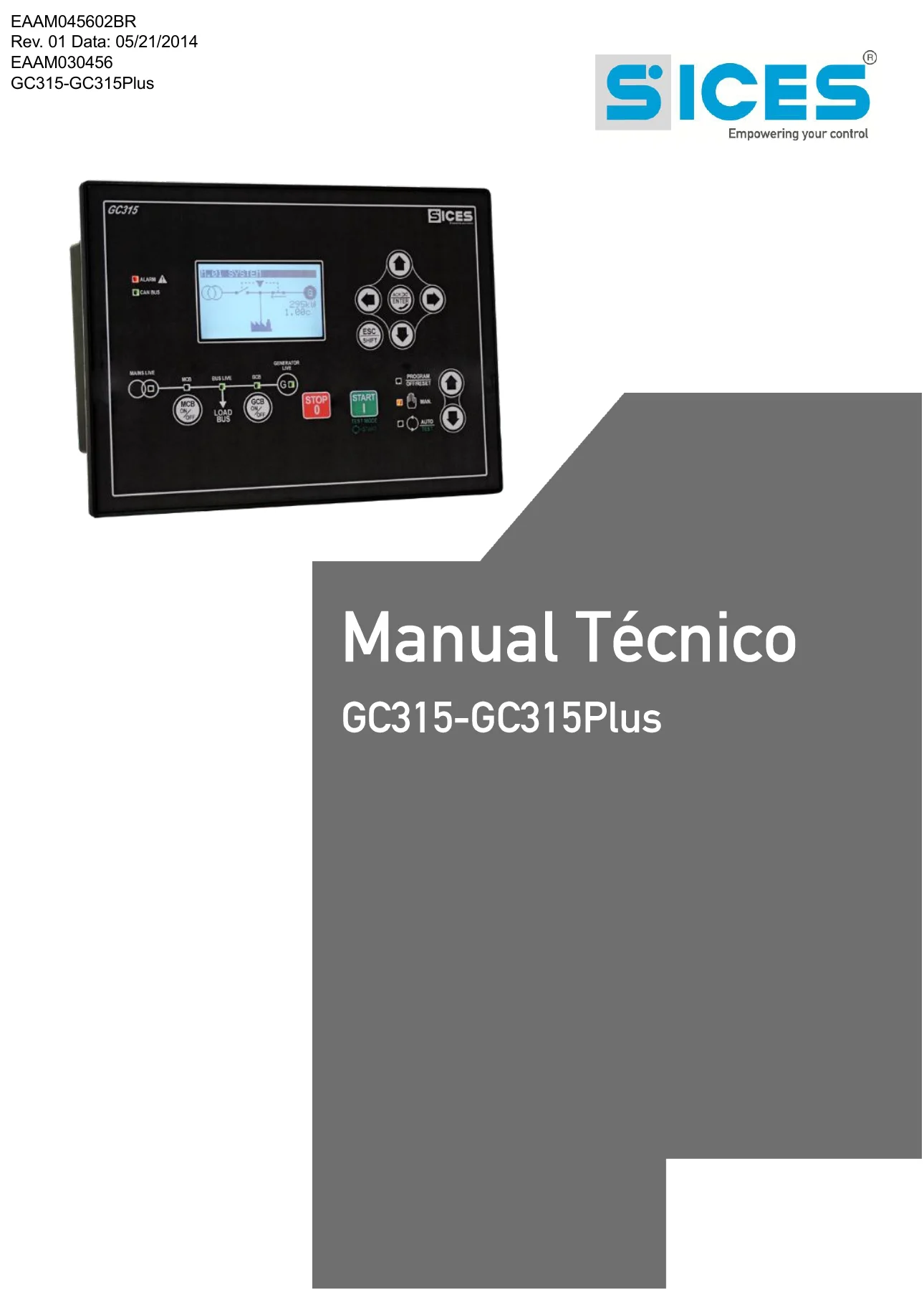
SICES GC315 & GC315Plus Genset Controller Technical Manual (EAAM045602BR)
Original price was: $29.95.$17.95Current price is: $17.95.
Complete SICES GC315/GC315Plus technical manual covering wiring, connectors, digital/analog I/O, parameters, alarms, and automatic operating modes for genset controllers. Instant PDF download.
Description
SICES GC315 & GC315Plus Genset Controller Technical Manual
This SICES GC315 and GC315Plus Genset Controller Technical Manual is the complete factory-issued reference for installing, wiring, configuring, and troubleshooting the GC315 and GC315Plus automatic mains failure (AMF) / auto-start controllers used on generator sets. If you work on generator control panels and need the exact connector layout, parameter codes, and alarm logic for this controller family, this manual gives you the full picture in one document.
- Manual type: Technical Manual
- Brand / model: SICES GC315 / GC315Plus
- Document number: EAAM045602BR (related code EAAM030456)
- Revision: 01
- Date: 05/21/2014
- Language: English
- Page count: 179 pages
- File format: PDF, instant digital download
Chapters Covered
- Introduction, safety warnings, and revision history
- Reference documentation and related SICES manuals
- General device description and technical characteristics (supply voltage, standby and operating current consumption)
- Voltage and current measurement specifications (TRMS, input impedance, current transformer requirements)
- Digital inputs, relay outputs, and static outputs
- Measurement accuracy tables (network/generator voltage, current, frequency, power, energy, engine speed, oil pressure, coolant temperature, fuel level)
- Panel installation and mounting dimensions
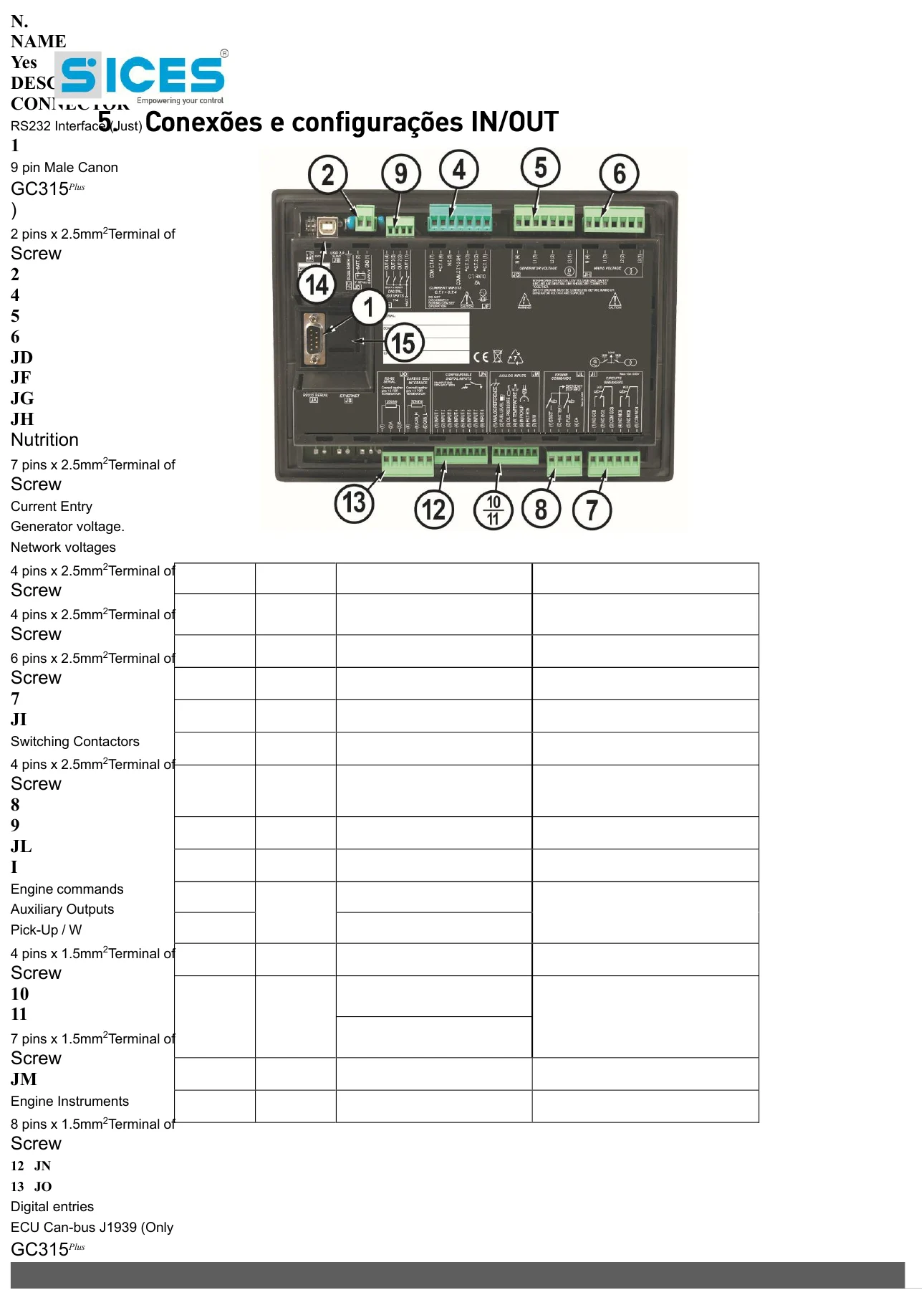
- Connector identification table (JC, JD, JE, JF, JG, JH, JI, JL, JM, JN, JO)
- Power supply wiring (JD connector) and grounding
- Start and fuel solenoid output wiring (JL connector) and excitation stop function
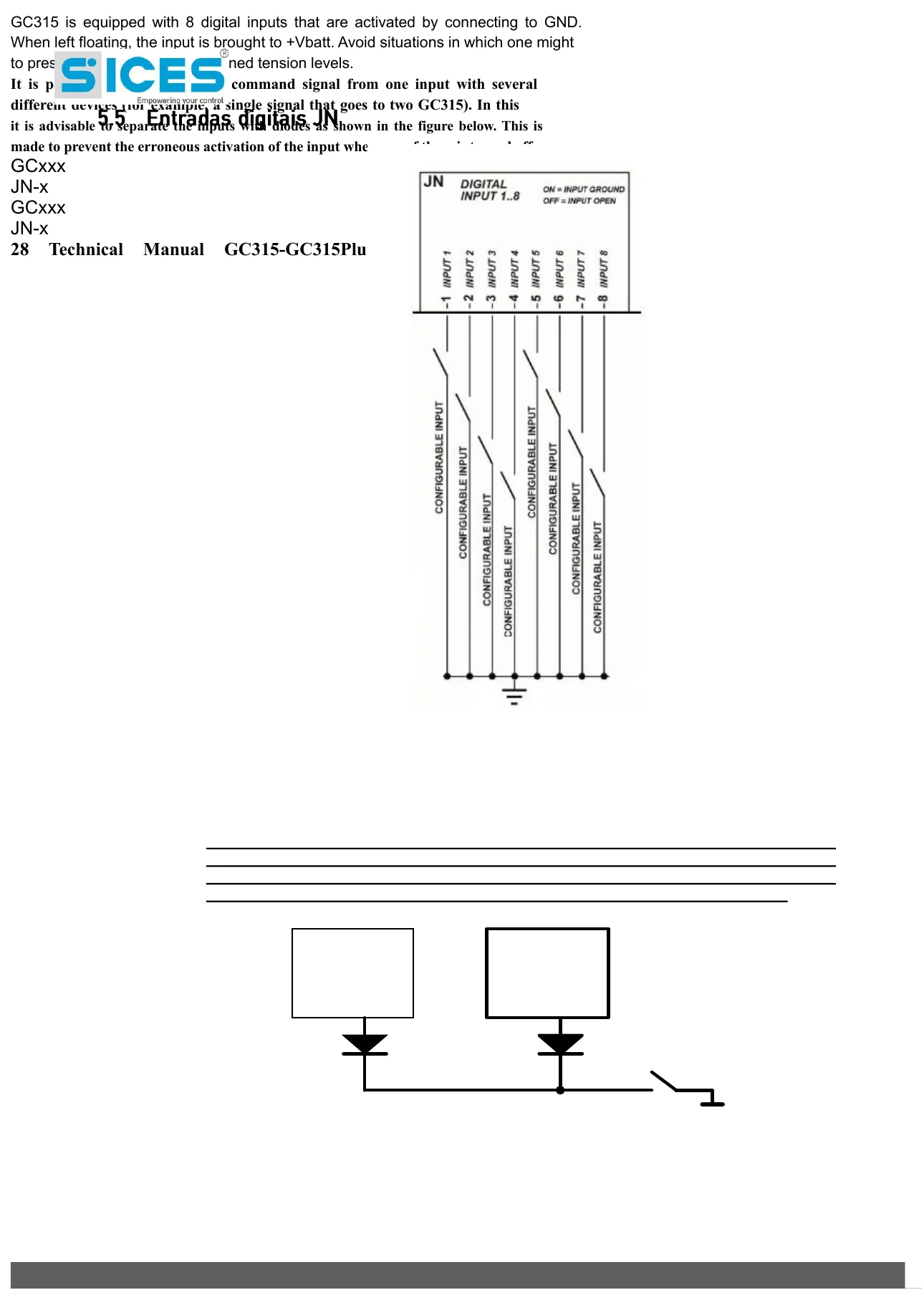
- Digital input wiring (JN connector), input sharing, and diode isolation
- Analog input configuration and use as additional digital inputs
- DITEL 16 IN expansion module and virtual inputs
- Digital input function codes (DIF.xxxx) with detailed descriptions
- Digital output function codes (DOF.xxxx) covering switch, fuel, and system anomalies
- Communication ports: USB Type B, RS232, and CAN-BUS J1939 (GC315Plus)
- Engine ECU diagnostics via CAN-BUS, SPN/FMI fault codes, and MTU MDEC engine examples
- Parameter programming via the BoardPrg3 PC software
- Full parameter index (P.xxxx) organized by function group
- Analog Virtual Function (AVF) and event (EVT) code tables
- Automatic mode logic, normal and emergency engine stop procedures
- Manual (MAN), Automatic (AUTO), Test, and Remote Start operating modes
- Weekly automatic-window and engine test-drive scheduling, including day-of-week bit configuration
- Internal clock/RTC behavior and historical event log recording
Beyond the individual function listings, the manual as a whole walks a technician through everything needed to bring a GC315 or GC315Plus panel from bare terminals to a fully configured, alarm-monitored automatic generator controller — from physical mounting and wiring through parameter-by-parameter configuration of every input, output, and protection function.
Digital, Analog, and Communication Details
The GC315/GC315Plus manual documents the controller’s 8 standard digital inputs plus expansion options (up to 32+ inputs via the optional DITEL 16 IN module), analog inputs that double as digital inputs, and 16 virtual inputs built from logical combinations. Relay and static output wiring for the starter motor, fuel solenoid, and alternator excitation (+D) circuits is fully diagrammed, along with the CAN-BUS J1939 interface used on the GC315Plus for direct communication with electronically controlled engines.
IMAGES PREVIEW
Alarms, Protections, and Diagnostics
Every digital input function (DIF), digital output function (DOF), and event (EVT) code referenced by the GC315/GC315Plus is documented, including switch status anomalies, fuel level and fuel pump faults, differential current protection, and CAN-BUS engine fault translation using SPN/FMI codes — giving technicians a direct path from a displayed alarm code back to its wiring and parameter source.
Why Technicians Rely on This SICES GC315 & GC315Plus Manual
With this SICES GC315/GC315Plus Genset Controller Technical Manual, you can correctly wire a new installation, reconfigure inputs and outputs to match a non-standard panel layout, resolve alarm and fault codes at the source, and program automatic test schedules with confidence. Working from the correct connector pinouts, parameter codes, and protection thresholds avoids guesswork that can damage the controller, the alternator excitation circuit, or connected switchgear. This is an instant PDF download — there’s no shipping or waiting. It downloads straight to your computer, tablet, or phone, works on any PDF reader, and can be printed or kept on-site for reference whenever you’re working on a GC315 or GC315Plus panel.
Reviews
There are no reviews yet.