
Siemens Avanto 1.5T Mobile MRI Trailer Oshkosh Operator and Service Manual (2006)
Original price was: $39.95.$24.95Current price is: $24.95.
Comprehensive operator and service manual for the 48-foot Oshkosh Specialty Vehicles mobile MRI trailer housing the Siemens MAGNETOM Avanto 1.5T system, covering setup, transport, HVAC, hydraulic lift, electrical distribution, and scheduled maintenance.
Description
Comprehensive Operating and Service Guide for Siemens Avanto 1.5T Mobile MRI Trailer
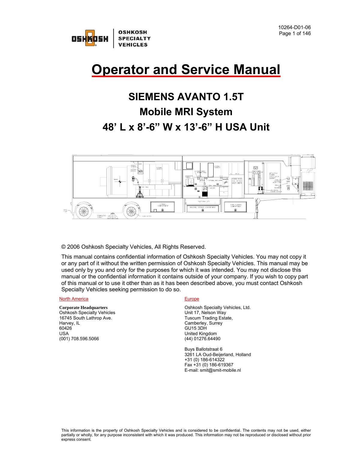
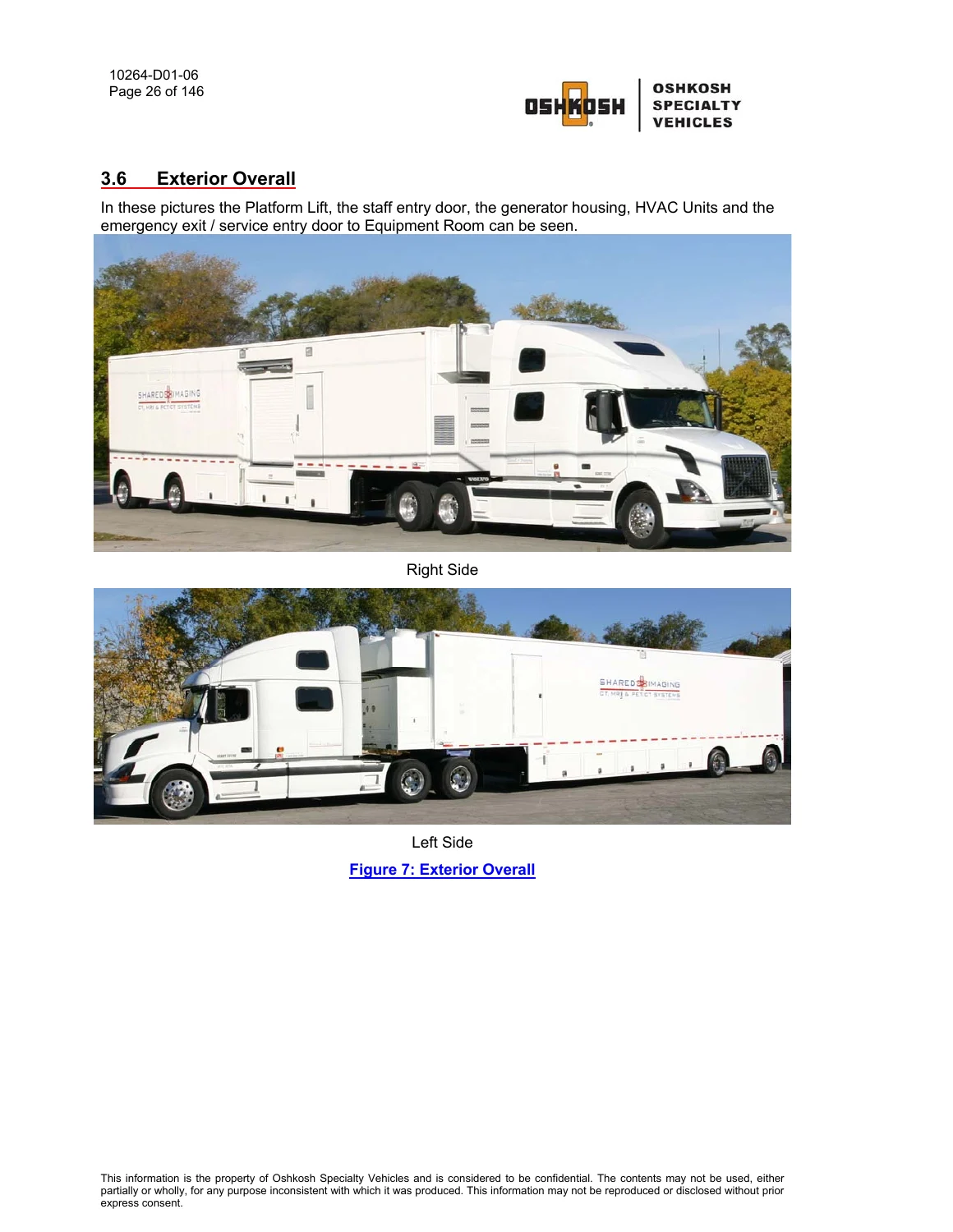
The Siemens Avanto 1.5T Mobile MRI Trailer Oshkosh Operator and Service Manual (2006) provides full operational protocols, staging instructions, transit procedures, and preventive maintenance tasks for operating the 48-foot Oshkosh Specialty Vehicles mobile medical unit. Configured specifically to support the Siemens MAGNETOM Avanto 1.5T mobile MRI platform, this specialized heavy-duty trailer integrates dedicated climate control, advanced power distribution, hydraulic platform lift mechanisms, and radio frequency (RF) shielding systems required to protect medical diagnostic imaging equipment in transit and during clinical pad operation.
File Details
- Document Type: Operator and Service Manual
- Equipment Brand: Oshkosh Specialty Vehicles / Siemens
- Model: Siemens Avanto 1.5T Mobile MRI System (48′ L x 8′-6″ W x 13′-6″ H USA Unit)
- Document Number: 10264-D01-06
- Publication Revision: Revision 05 (October 2006)
- Language: English
- Page Count: 146 pages
- Format: Digital PDF
Chapters Covered
- Section 1: Introduction – Operational overview, qualified personnel directives, and manufacturer limitations
- Section 2: Safety Guidelines – General precautions, magnet exclusion zone safety, cryogen handling, electrical hazards, and transportation safety
- Section 3: Mobile Unit Overview – Air ride controls, retractable canopy, control room, cryogen compressor, equipment room, exterior compartments, glad-hands, Hubbell cables, scan room, magnet room, and stabilizing stands
- Section 4: Safety Systems – Door interlock monitoring, emergency exit, dual beam emergency lighting, fire detection/suppression, gauss line restrictions, roll door safety, and emergency rundown / A-1 shutdowns
- Section 5: Mobile Unit Setup Procedure – Pad parking, landing gear extension, tractor uncoupling, rear stabilizing stands installation, leveling, shore power connection, line switching, water supply fill, and system preparation
- Section 6: Mobile Unit Transport Procedure – Equipment restraint, shore-to-generator transfer, platform lift stowage, stair removal, auxiliary legs retraction, tractor coupling, and pre-trip verification checklists
- Section 7: Electrical System – 120/208V AC panel, 480V AC distribution panel, Russellstoll facility connectors, power cable ratings, and earth ground rod requirements
- Section 8: Generator – Front-mounted Kohler Power Systems diesel generator, stop/start sequencing, cooling cycle, power selector transfer, and 480V fault monitoring
- Section 9: HVAC System – Combination air conditioning and liquid chiller, Northern Air configurations, steam cylinder humidifier operation, duct heaters, and underbody compartment freeze protection
- Section 10: Platform Lift – Electro-hydraulic 2000 lb capacity lift, torsion-assisted platform operation, micro switches, retaining cradles, transport pins, and warning circuits
- Section 11: Intrusion Alarm – Security keypad programming, door contacts, and internal motion detection
- Section 12: Landing / Stabilizing Legs – Front hydraulic landing legs, auxiliary pin support legs, sand shoes, and rear air suspension deflation controls
- Section 13: Lighting System – Interior scan/control room illumination, service drop lighting, underbody compartment lighting, and tractor-powered marker lights
- Section 14: General Maintenance – Daily visual inspections, weekly fluid checks, monthly mechanical lubrications, and quarterly service schedules
- Section 15: Specific Maintenance – Door closer adjustments, terminal bolt torquing, cryogen compressor servicing, humidifier maintenance, and RF shielding verification
- Appendix A: Mobile Unit Checklists – Formal setup checklist and transport departure checklist
- Appendix B: Troubleshooting – Fault resolution for platform lift, power indicators, warning strobes, suspension lights, humidity variance, and temperature faults
- Appendix C: HVAC Set Points – Factory environmental parameters for scan room (67°F), control room (68°F), and relative humidity (50% RH)
- Appendix D: A-1 Circuit Malfunction Checklist – Category 1 visual checks and Category 2 electrical contact tests
- Appendix E: Lockout/Tagout Procedures – OSHA 1910.147 energy control guidelines for 480V AC, 120V AC, and 12V DC circuits
- Appendix F: Portable Oxygen Monitor – Teledyne Model MX300-I service instructions, sensor care, calibration routines, error codes, and alarm testing
- Appendix G: Quarterly Maintenance Checklist – Master multi-point service verification logs
This technical documentation equips clinical biomedical engineers, mobile operations managers, and transport specialists with the necessary diagnostic protocols, hydraulic control instructions, environmental specifications, and structural setup tasks required to maintain peak uptime across all operational phases.
Mobile Pad Staging and Operational Deployment
Proper pad placement is critical to prevent scan artifacts and structural fatigue. This manual provides direct step-by-step procedures for positioning the 48-foot trailer on the concrete pad in alignment with facility site-planning guides. Technicians are guided through operating the front hydraulic landing legs, clearing the fifth wheel, lowering the mechanical auxiliary support legs to within 0.5 inches of the sand shoes, and installing the heavy-duty rear stabilizing stands. Complete instructions are included for operating the rear air suspension control valves to inflate the air bags for stand insertion, followed by complete air suspension exhaustion so the trailer rests firmly on the stabilizing stands to eliminate vibration during medical imaging scans.
Facility Power Interconnection and Electrical Distribution
Operating a high-field magnetic resonance system on a mobile platform requires rigorous electrical safety protocols. The manual outlines incoming utility connections utilizing a 200A Russellstoll DF 2504 FRAB 0 facility receptacle and the provided 50-foot #3/0 4-conductor Type G 600V–2000V rated power cable. Operating personnel will find detailed coverage of the 480V AC main distribution panel, the 120/208V AC auxiliary panel, and the dedicated A-1 medical distribution cabinet. It delivers step-by-step instructions for transitioning from generator power to shore line power, incorporating mandatory 5-second pauses in the ‘OFF’ position to prevent electrical phase damage, as well as grounding requirements utilizing earth-driven rods within 5 feet of the hospital service receptacle.
Onboard Diesel Generator and Road Transport Protocols
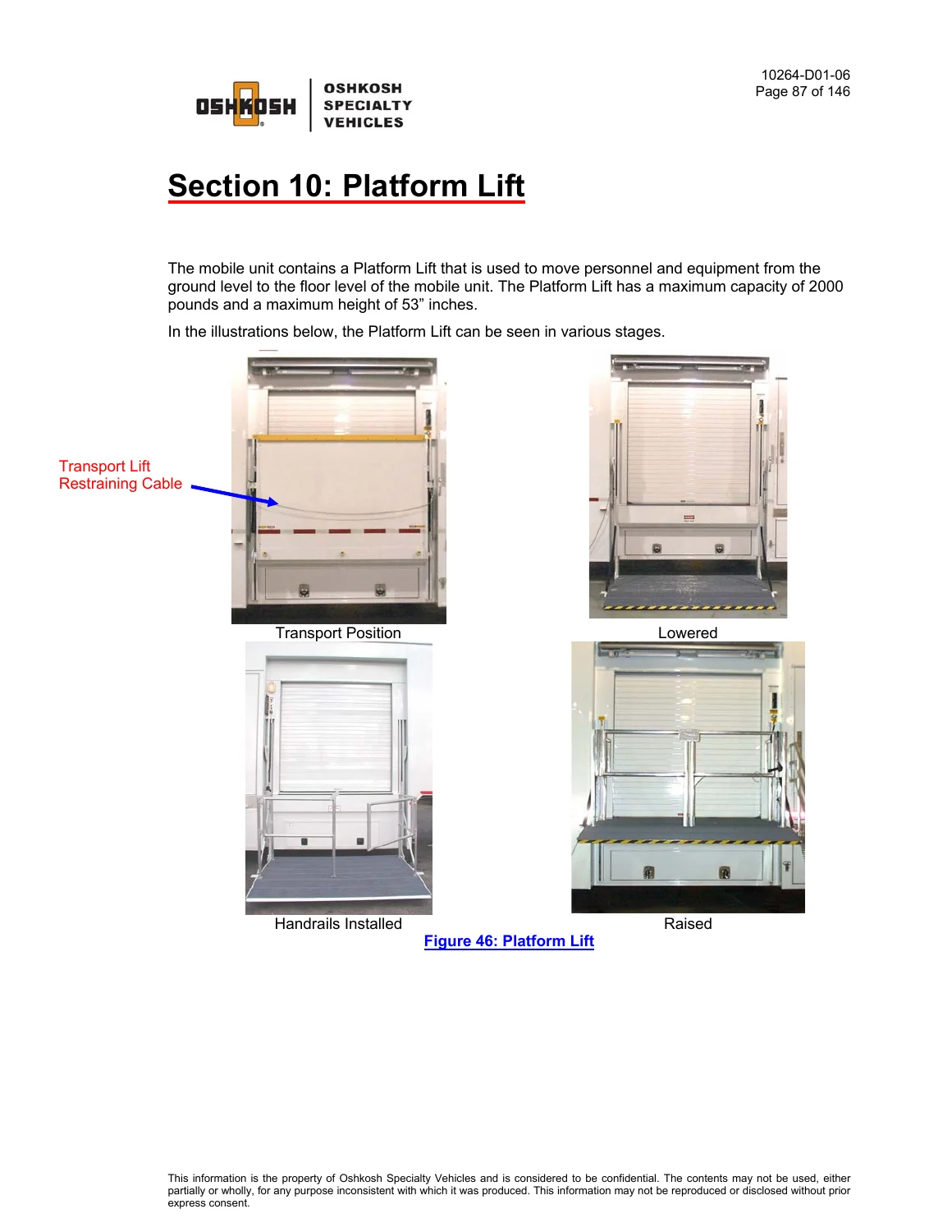
When in transit between clinical sites, the trailer relies on an integrated front-housing Kohler Power Systems diesel generator fed by a 70-gallon dedicated diesel fuel tank. The manual documents cold start protocols, generator load management, warmup and cooldown five-minute timing phases, and regular filter changes. Road travel preparation includes stowing the stair system in underbody storage, pinning the auxiliary support legs into their highest transport position, retracting the hydraulic platform lift into its retaining cradles, engaging safety transport pins to actuate safety micro-switches, and inflating the air suspension to normal ride height (15 inches from trailer sidewall to ground level).
IMAGES PREVIEW
Environmental Control, Humidification, and RF Shielding Integrity
The Siemens Avanto magnet requires constant environmental stability. The documentation covers the closed-loop Northern Air commercial HVAC system, which incorporates dual refrigeration stages and an integrated water chiller supplying a 50/50 ethylene glycol mix to the magnet shield cooler compressor. Instructions specify return duct sensor operation, in-duct electric heaters, and the electrode-based steam cylinder humidifier capable of producing up to 12 pounds of steam per hour to maintain relative humidity strictly at 50% RH (limits 30% to 60%). Critical instructions also address the certified 90 dB radio frequency shielding enclosure, maintenance of beryllium copper finger stock door gaskets using denatured alcohol, and RF door interlock circuits that halt imaging scans if an access door opens.
Service Capability, Warranty Protection, and Instant Delivery
The Siemens Avanto 1.5T Mobile MRI Trailer Oshkosh Operator and Service Manual (2006) is essential for biomedical technicians, field service engineers, and commercial transport drivers tasked with managing mobile MRI operations. Adhering strictly to Oshkosh Specialty Vehicles operating routines prevents structural damage, protects the sensitive helium cryostat, and ensures full compliance with Siemens Magnet Technology Specification MS001 to keep OEM warranties valid. Available as an instant PDF download immediately upon checkout, this comprehensive digital manual is fully viewable across desktop computers, field laptops, and mobile tablets, or printable for quick workshop access on the clinical service pad.
Reviews
There are no reviews yet.