SIEMENS Drive Converter Cabinet Cat Bucyrus Shovel 182M AC Operation & Maintenance Manual – PDF DOWNLOAD
$28.95
SIEMENS Drive Converter Cabinet Cat Bucyrus Shovel 182M AC Operation & Maintenance Manual – PDF DOWNLOAD
Description
SIEMENS Drive Converter Cabinet Cat Bucyrus Shovel 182M AC Operation & Maintenance Manual – PDF DOWNLOAD
FILE DETAILS:
SIEMENS Drive Converter Cabinet Cat Bucyrus Shovel 182M AC Operation & Maintenance Manual – PDF DOWNLOAD
Language : English
Pages :282
Downloadable : Yes
File Type : PDF
DESCRIPTION:
SIEMENS Drive Converter Cabinet Cat Bucyrus Shovel 182M AC Operation & Maintenance Manual – PDF DOWNLOAD
Safety Guidelines
A Definitions, Warnings
Qualified personnel
For the purpose of this instruction manual and the warning labels on the product
itself, a qualified person is someone who is familiar with the installation, mounting,
starting up and operation of the equipment and the hazards involved.
He or she must have the following qualifications.
• Trained and authorized to energize, de-energize, clear, ground and tag circuits
and equipment in accordance with established safety procedures
• Trained in the proper care and use of protective equipment in accordance with
established safety procedures
• Trained in rendering first aid
Safety guidelines
This manual contains notes that you should observe to ensure your own personal safety, as well to protect the product and connected equipment. These notes are highlighted in the manual by a warning triangle. Notes regarding property damage alone are not accompanied by a warning triangle. Notes are marked as follows according to the level of danger.
IMAGES PREVIEW OF THE MANUAL:
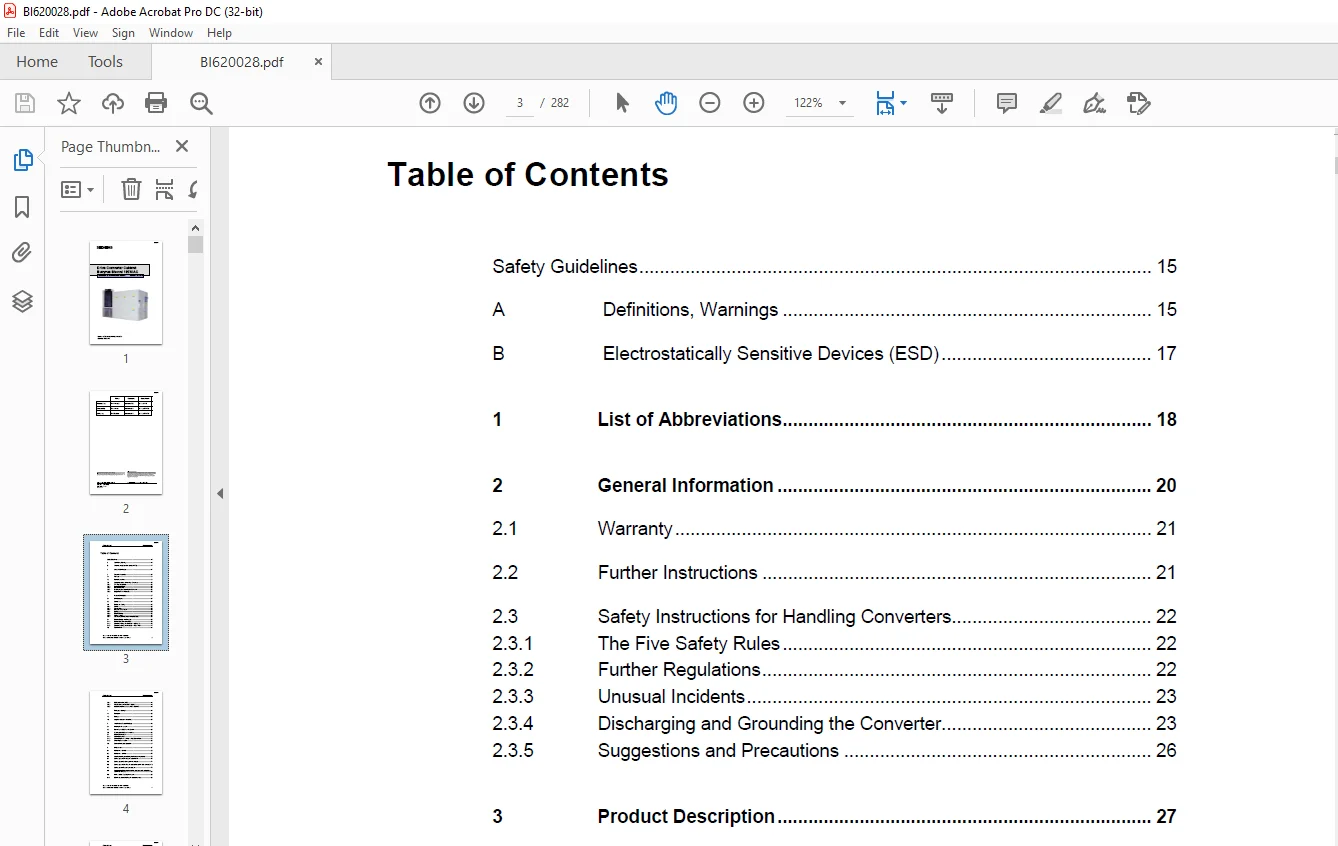
TABLE OF CONTENTS:
SIEMENS Drive Converter Cabinet Cat Bucyrus Shovel 182M AC Operation & Maintenance Manual – PDF DOWNLOAD
Safety Guidelines 15
A Definitions, Warnings 15
B Electrostatically Sensitive Devices (ESD) 17
1 List of Abbreviations 18
2 General Information 20
2 1 Warranty 21
2 2 Further Instructions 21
2 3 Safety Instructions for Handling Converters 22
2 3 1 The Five Safety Rules 22
2 3 2 Further Regulations 22
2 3 3 Unusual Incidents 23
2 3 4 Discharging and Grounding the Converter 23
2 3 5 Suggestions and Precautions 26
3 Product Description 27
3 1 Brief Description 27
3 2 Correct Use 27
3 3 Design and Cooling 28
3 3 1 Overview 28
3 3 2 Physical Data 29
3 3 3 Insulation Coordination 29
3 3 4 Cooling 32
3 3 5 Electrical Design 32
3 3 6 Cooling System 33
3 3 7 List of Components for Shovel 182MAC DCC 35
3 4 Electrical Design and Function 39
3 4 1 Functional sections of the DCC 39
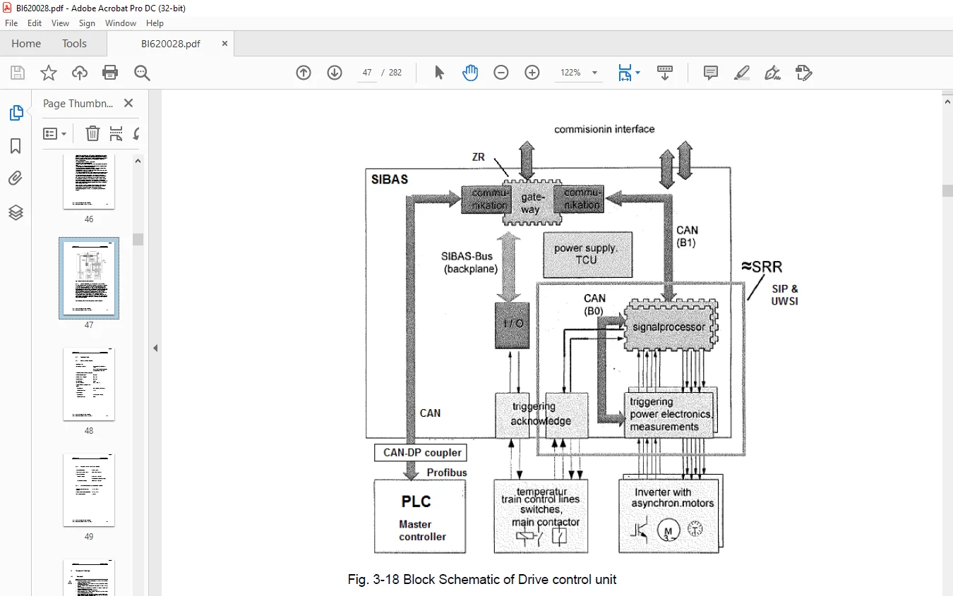
3 4 2 Control Monitoring and Protection – SIBAS 32S 46
3 4 3 Control Monitoring and Protection – PLC S7 400 47
3 5 Technical Data 48
3 5 1 DCC for Shovel 182MAC 48
3 5 2 Physical data for Shovel DCC 182MAC 49
3 5 3 Ambient conditions for Shovel DCC 182MAC 49
4 Transport / Storage 50
4 1 Transport 50
4 2 Storage 56
4 3 Long-time storage (> 6 months) 58
5 Installation & Commissioning 59
5 1 Installing in the Shovel 59
5 2 Removing the DCC from the Shovel 60
5 3 Welding of the DCC on the machine 61
5 4 Electrical Connections 62
5 4 1 Power Connections 62
5 4 2 Control Circuit and Auxiliary Voltage Connections 64
5 4 3 Grounding Connections 66
5 5 Commissioning and Operation 67
6 Maintenance 68
6 1 Maintenance schedule 69
6 2 Maintenance activities 70
6 3 Visually checking and cleaning the heat exchanger (E02) 72
6 4 Cooling system: Checking the coolant level 73
6 5 Cooling system: Coolant specimen, analysis 74
6 6 Cooling system: Checking the seals at the coolant liquid connections75
6 7 Cooling system: Replacing the coolant 75
6 8 Coolant pump: Replacing the coolant pump and overhauling it in an
authorized workshop 80
6 9 Internal cooler: Replacing the motor 80
6 10 DC link capacitor: Checking the capacitance value 80
6 11 Main blower fan motor: Replacing the bearings 81
6 12 DCC: Cleaning the inner space 81
6 13 Checking the main and auxiliary contacts of the contactors, transfer
switch and the busbar connections in the DCC 82
6 14 Cooling system: Checking for porous hoses 83
6 15 DCC: Checking the painted surfaces 83
6 16 Replacing seals at the maintenance covers 83
6 17 Air conditioner: cleaning the heatsink fins 84
7 Maintenance, Trouble-Shooting and Repairs 85
7 1 Discharging and Grounding the Converter 85
7 2 Component locations in DCC 86
7 3 MOTOR MODULE,24VDC 90
7 3 1 Description 90
7 3 2 Testing 90
7 3 3 Replacing 91
7 3 4 Drawing 93
7 3 5 Technical data 93
7 4 SWITCH MODULE 94
7 4 1 Description 94
7 4 2 Testing 94
7 4 3 Replacing 94
7 4 4 Drawing 96
7 4 5 Technical data 96
7 5 IGBT MODULE,DOUBLE,SD-1500WL 97
7 5 1 Description 97
7 5 2 Testing 98
7 5 3 Replacing 100
7 5 4 Drawing 102
7 5 5 Technical data 102
7 6 IGBT MODULE,TRIPLE,ST-1500WL-HP 103
7 6 1 Description 103
7 6 2 Testing 104
7 6 3 Replacing 106
7 6 4 Drawing 108
7 6 5 Technical data 108
7 7 CROWBAR MODULE,CBH-1500L 109
7 7 1 Description 109
7 7 2 Testing 110
7 7 3 Replacing 110
7 7 4 Drawing 111
7 7 5 Technical data 111
7 8 CHOKE,400uH,3300V,358A,182MAC 112
7 8 1 Description 112
7 8 2 Testing 112
7 8 3 Replacing 112
7 8 4 Drawing 114
7 8 5 Technical data 114
7 9 CONTACTOR,2P,1500V,650A 115
7 9 1 Description 115
7 9 2 Testing 115
7 9 3 Replacing 115
7 9 4 Drawing 117
7 9 5 Technical data 117
7 10 CONTACTOR,1P,1500V,250A 118
7 10 1 Description 118
7 10 2 Testing 118
7 10 3 Replacing 118
7 10 4 Drawing 119
7 10 5 Technical data 120
7 11 RES,CHOPPER,3 15,1000W 120
7 11 1 Description 120
7 11 2 Testing 120
7 11 3 Replacing 121
7 11 4 Drawing 122
7 11 5 Technical data 122
7 12 BLOWER,3PH RADIAL,182MAC 123
7 12 1 Description 123
7 12 2 Testing 123
7 12 3 Replacing 123
7 12 4 Drawing 125
7 12 5 Technical data 125
7 13 COOLER, 35 06KW AKG 126
7 13 1 Description 126
7 13 2 Testing 126
7 13 3 Replacing 126
7 13 4 Drawing 128
7 13 5 Technical data 129
7 14 COOLER,AIR/WATER,6KW AKG 129
7 14 1 Description 129
7 14 2 Testing 129
7 14 3 Replacing 130
7 14 4 Drawing 131
7 14 5 Technical data 131
7 15 PUMP,CENTRIF,415V,182MAC 132
7 15 1 Description 132
7 15 2 Testing 132
7 15 3 Replacing 132
7 15 4 Drawing 134
7 15 5 Technical data 134
7 16 CAP,MKP DC,3 mF,2050V 135
7 16 1 Description 135
7 16 2 Testing 135
7 16 3 Replacing 135
7 16 4 Drawing 137
7 16 5 Technical data 137
7 17 CONVERTER,DC-DC,150W 138
7 17 1 Description 138
7 17 2 Testing 138
7 17 3 Replacing 138
7 17 4 Drawing 139
7 17 5 Technical data 140
7 18 POWER SUPPLY,48V/20A 142
7 18 1 Description 142
7 18 2 Testing 142
7 18 3 Replacing 143
7 18 4 Drawing 143
7 18 5 Technical data 144
7 19 CT,HALL EFFECT,LF2005-S/SP28 145
7 19 1 Description 145
7 19 2 Testing 145
7 19 3 Replacing 145
7 19 4 Drawing 147
7 19 5 Technical data 147
7 20 PCB ASSY,QPSW 2KV 148
7 20 1 Description 148
7 20 2 Testing 148
7 20 3 Replacing 149
7 20 4 Drawing 150
7 20 5 Technical data 150
7 21 VOLTAGE TRANSDUCER,300V 151
7 21 1 Description 151
7 21 2 Testing 151
7 21 3 Replacing 152
7 21 4 Drawing 152
7 21 5 Technical data 153
7 22 FILTER,74V,8A,40% 154
7 22 1 Description 154
7 22 2 Testing 154
7 22 3 Replacing 155
7 22 4 Drawing 155
7 22 5 Technical data 155
7 23 PRESSURE TRANSDUCER 156
7 23 1 Description 156
7 23 2 Testing 156
7 23 3 Replacing 156
7 23 4 Drawing 157
7 23 5 Technical data 157
7 24 RES,WW,60R,1000W,5% 158
7 24 1 Description 158
7 24 2 Testing 158
7 24 3 Replacing 158
7 24 4 Drawing 159
7 24 5 Technical data 160
7 25 RES,WW,33K,300W,5% 160
7 25 1 Description 160
7 25 2 Testing 160
7 25 3 Replacing 161
7 25 4 Drawing 161
7 25 5 Technical data 162
7 26 RES,WW,99K,300W,5% 163
7 26 1 Description 163
7 26 2 Testing 163
7 26 3 Replacing 163
7 26 4 Drawing 164
7 26 5 Technical data 165
7 27 CAP,MKV,0 22 Uf,5000V 166
7 27 1 Description 166
7 27 2 Testing 166
7 27 3 Replacing 166
7 27 4 Drawing 167
7 27 5 Technical data 167
7 28 AUX CONTACTORS FOR TRANSFER SWITCH 168
7 28 1 Description 168
7 28 2 Testing 168
7 28 3 Drawing 168
7 28 4 Technical data 169
7 29 AUX CONTACTOR, 120VAC 171
7 29 1 Description 171
7 29 2 Testing 171
7 29 3 Drawing 171
7 29 4 Technical data 171
7 30 AUX CONTACTOR, 24VDC 173
7 30 1 Description 173
7 30 2 Testing 173
7 30 3 Drawing 174
7 30 4 Technical data 174
7 31 SIBAS,6FH4808-1A,182MAC 176
7 31 1 Description 176
7 31 2 Testing 176
7 31 3 Replacing 176
7 31 4 Technical data 177
7 32 HEATER,800W 178
7 32 1 Description 178
7 32 2 Testing 178
7 32 3 Replacing 179
7 32 4 Drawing 180
7 32 5 Technical data 180
7 33 POWER SUPPLY (QUINT-PS-100-240AC/24DC/40A) 181
7 33 1 Description 181
7 33 2 Testing 181
7 33 3 Technical data 182
7 34 SIMATIC S7-400, UR1 RACK WITH 18 SLOTS 183
7 34 1 Description 183
7 34 2 Drawing 183
7 34 3 Technical data 183
7 35 DIGITAL I/P MODULE (120VAC, 32 CH) 184
7 35 1 Description 184
7 35 2 Drawing 184
7 35 3 Technical data 185
7 36 DIGITAL O/P MODULE (120VAC, 32 CH) 185
7 36 1 Description 185
7 36 2 Drawing 186
7 36 3 Technical data 187
7 37 DIGITAL I/P MODULE (24V DC 32 CH) 188
7 37 1 Description 188
7 37 2 Technical data 188
7 38 DIGITAL O/P MODULE (24V DC 32 CH) 191
7 38 1 Description 191
7 38 2 Technical data 191
7 39 SIMATIC S7-400, ANALOG INPUT SM 431, NON-ISOLATED 16 AI192
7 39 1 Description 192
7 39 2 Drawing 192
7 39 3 Technical data 193
7 40 SIMATIC S7-400, ANALOG OUPUT SM 432, NON-ISOLATED 08 AO195
7 40 1 Description 195
7 40 2 Drawing 195
7 40 3 Technical data 196
7 41 SIMATIC S7-400, PS 407 POWER SUPPLY, 10A 197
7 41 1 Description 197
7 41 2 Drawing 197
7 41 3 Technical data 198
7 42 SIMATIC S7-400, CPU 416-2 200
7 42 1 Description 200
7 42 2 Drawing 200
7 42 3 Technical data 201
7 43 SIMATIC NET, CP 443-1 COMM PROCESSOR FOR ETHERNET
CONNECTION 206
7 43 1 Description 206
7 43 2 Technical data 207
7 44 CAN DP COUPLER 209
7 44 1 Description 209
7 44 2 Testing 209
7 44 3 Drawing 210
7 44 4 Technical data 211
7 45 SIMATIC PANEL PC 677B 212
7 45 1 Description 212
7 45 2 Testing 212
7 45 3 Replacing 214
7 45 4 Drawing 215
7 45 5 Technical data 216
7 46 AIR CONDITIONER 222
7 46 1 Description 222
7 46 2 Testing 223
7 46 3 Replacing 223
7 46 4 Drawing 224
7 46 5 Technical data 224
7 47 CIRCUIT BREAKERS 225
7 47 1 Description 225
7 47 2 Drawing 226
7 47 3 Technical data 226
7 48 EMERGENCY STOP PUSH BUTTON 227
7 48 1 Description 227
7 48 2 Testing 227
7 48 3 Drawing 228
7 48 4 Technical data 228
7 49 RESET PUSH BUTTON 229
7 49 1 Description 229
7 49 2 Testing 229
7 49 3 Drawing 229
7 49 4 Technical data 230
7 50 SITOP DC UPS MODULE 24V 231
7 50 1 Description 231
7 50 2 Testing 231
7 50 3 Replacing 231
7 50 4 Drawing 232
7 50 5 Technical data 232
7 51 UPS MODULE POWER SUPPLY (QUINT-PS-100-240AC/24DC/20A)233
7 51 1 Description 233
7 51 2 Testing 233
7 51 3 Replacing 233
7 51 4 Drawing 234
7 51 5 Technical data 234
7 52 SITOP POWER BATTERY MODULE 24V/7Ah 235
7 52 1 Description 235
7 52 2 Testing 235
7 52 3 Replacing 236
7 52 4 Drawing 236
7 52 5 Technical data 237
7 53 FAN SUBASSEMBLY 28 SEP 1U 238
7 53 1 Description 238
7 53 2 Replacing 238
7 53 3 Technical data 239
7 54 INPUT/OUTPUT MODULE 240
7 54 1 Description 240
7 54 2 Replacing 240
7 54 3 Diagram 240
7 54 4 Technical data 241
7 55 INPUT VOLTAGE/ FREQUENCY 243
7 55 1 Description 243
7 55 2 Replacing 243
7 55 3 Diagram 244
7 55 4 Technical data 244
7 56 INPUT CONVERTER BINARY 24V 245
7 56 1 Description 245
7 56 2 Replacing 245
7 56 3 Diagram 246
7 56 4 Technical data 246
7 57 OUTPUT MEASURING AMPLIFIER 247
7 57 1 Description 247
7 57 2 Replacing 247
7 57 3 Diagram 248
7 57 4 Technical data 248
7 58 INPUT TEMPERATURE SENSOR PT100 250
7 58 1 Description 250
7 58 2 Replacing 250
7 58 3 Diagram 251
7 58 4 Technical data 251
7 59 DC/DC CONVERTER 72 110V/24V 100W 254
7 59 1 Description 254
7 59 2 Testing 254
7 59 3 Replacing 254
7 59 4 Diagram 255
7 59 5 Technical data 255
7 60 DC/DC CONVERTER 72 110V/+-15V 100W 257
7 60 1 Description 257
7 60 2 Testing 257
7 60 3 Replacing 257
7 60 4 Diagram 258
7 60 5 Technical data 258
7 61 BINARY OUTPUT 24V 36V/2 A 259
7 61 1 Description 259
7 61 2 Replacing 259
7 61 3 Diagram 260
7 61 4 Technical data 260
7 62 INVERTER MONITORING CURRENT LINK 262
7 62 1 Description 262
7 62 2 Replacing 262
7 62 3 Diagram 263
7 62 4 Technical data 263
7 63 MAINBOARD SIP 265
7 63 1 Description 265
7 63 2 Replacing 265
7 63 3 Diagram 266
7 63 4 Technical data 267
7 64 CONVERTER 72 110V/5V 90W 268
7 64 1 Description 268
7 64 2 Testing 268
7 64 3 Replacing 268
7 64 4 Diagram 269
7 64 5 Technical data 269
7 65 POWER START-UP UNIT 270
7 65 1 Description 270
7 65 2 Testing 271
7 65 3 Replacing 271
7 65 4 Diagram 272
7 65 5 Technical data 273
7 66 CPU 586 274
7 66 1 Description 274
7 66 2 Replacing 274
7 66 3 Diagram 275
7 66 4 Technical data 276
8 Appendix 277
8 1 Appendix A: Special Tools 277
8 2 Appendix B: Tightening Torque 279
8 3 Appendix C: Return authorization form 280
Need help? Contact: [email protected]
https://vimeo.com/861577646?share=copy
PLEASE NOTE:
- This is the SAME exact manual used by your dealers to fix your vehicle.
- The same can be yours in the next 2-3 mins as you will be directed to the download page immediately after paying for the manual.
- Any queries / doubts regarding your purchase, please feel free to contact [email protected]
S.M