
Sikorsky S-92A Wiring System Manual SA S92A-WSM-000 – PDF Download
Original price was: $44.95.$25.95Current price is: $25.95.
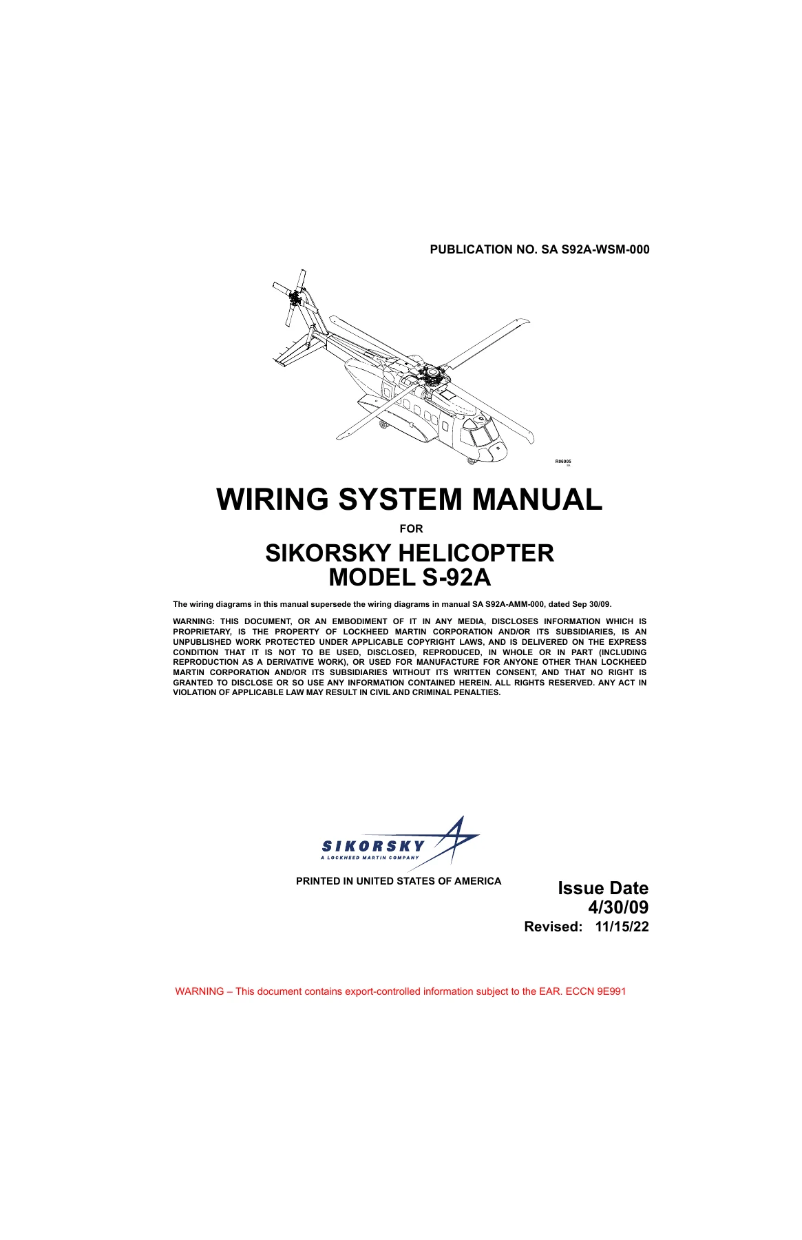
Complete wiring system manual for the Sikorsky S-92A helicopter, covering all electrical systems, wiring diagrams, connectors, and harness routing across 24 ATA chapters. Publication SA S92A-WSM-000.
Description
Sikorsky S-92A Wiring System Manual — SA S92A-WSM-000
This Sikorsky S-92A Wiring System Manual (Publication No. SA S92A-WSM-000) is the dedicated wiring documentation set for the Sikorsky S-92A helicopter. It contains the complete wiring diagrams, schematics, and system interconnect information necessary for electrical troubleshooting, maintenance, repair, and system understanding. The manual is organized by ATA chapter, following the aircraft’s standard numbering system, and covers every major electrical and avionics system installed on the S-92A.
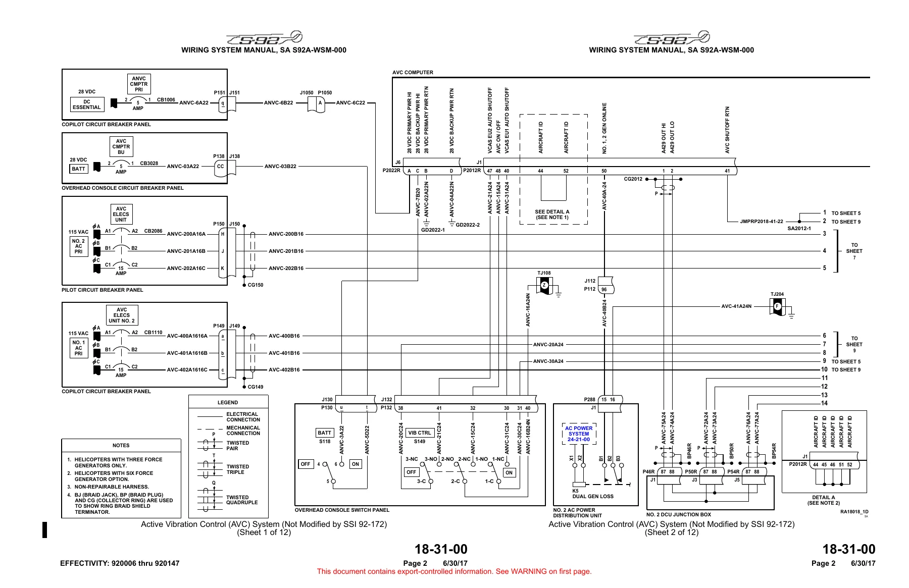
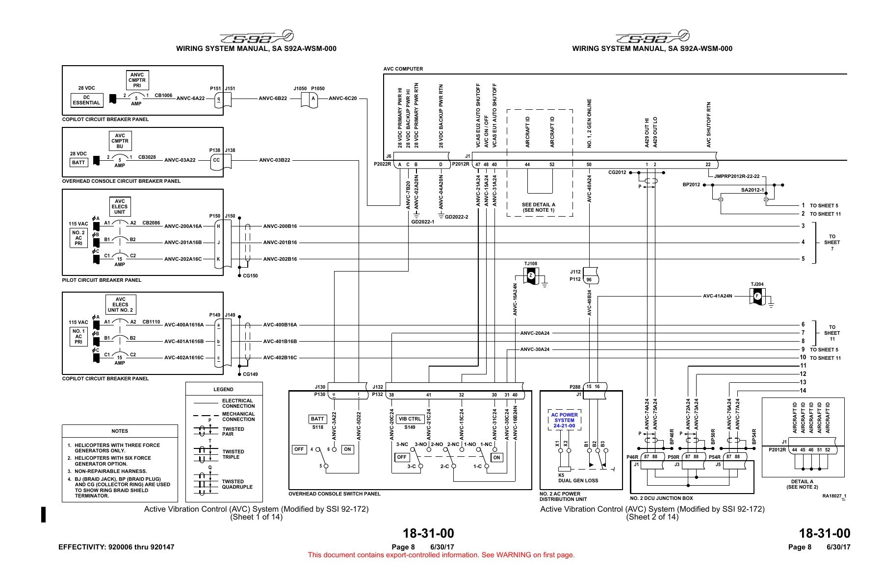
Whether you are tracing a fault in the electrical power distribution system, verifying a connector pinout in the avionics bay, or studying the wiring architecture of the active vibration control system, this Sikorsky S-92A Wiring System Manual provides the detailed schematics and system-level diagrams required to perform the work accurately. The document is written in English and is presented as a high-resolution PDF that can be viewed on any device.
File Details
- Manual Type: Wiring System Manual
- Publication Number: SA S92A-WSM-000
- Brand / Manufacturer: Sikorsky (Lockheed Martin Company)
- Model: S-92A Helicopter
- Language: English
- Page Count: Approximately 688 pages
- File Format: PDF
- Issue Date: 4/30/09
- Revised: 11/15/22
- Country of Publication: United States of America
The manual supersedes the wiring diagrams previously published in SA S92A-AMM-000, dated Sep 30/09, making this the current and authoritative wiring reference for the S-92A.
Chapters Covered
The Sikorsky S-92A Wiring System Manual is organized into the following ATA chapters, each containing the wiring diagrams and system interconnect data for that aircraft system:
- Chapter 18 — Vibration and Noise Analysis: Active Vibration Control (AVC) System, covering configurations for helicopters 920006 thru 920147 (modified and not modified by SSI 92-172) and helicopters 920148 and subsequent
- Chapter 21 — Air Conditioning: Avionics Cooling System, Heating and Ventilating System (with and without ECS), Air Conditioning System for various helicopter configurations
- Chapter 22 — Auto Flight: Automatic Flight Control System (AFCS), including accelerometers, FCC cross-channel data link, SAS, WOW and rotor brake interface, rate gyros and AHRS interface, trim, power distribution and engage-disengage
- Chapter 23 — Communications: VHF Radio Systems No. 1 and No. 2 (including VHF-4000F modified by SSI 92-152), NPX-138 VHF FM Radio System, KHF 1050 HF Communication System (basic, Comm Port 5, and DACS Comm Port 5 configurations), Skytracs Voice Enabled Flight Following, Chelton TETRA Transceiver, Blue Sky Network Voice/Data, Mode S Transponder systems, Mission Audio System, Interphone System, Radio Tuning Units (RTU), Backup Comm/Nav Controller, Radio Guard Panels
- Chapter 24 — Electrical Power: AC Power System, DC Power System, Auxiliary DC Power System
- Chapter 25 — Equipment/Furnishings: Raft, Emergency Locator Transmitter (ELT), ELB-3000 Deployable Emergency Beacon, CPI 15-503 Deployable Emergency Beacon, Single and Dual Electric Rescue Hoist Systems, Rescue Hoist Shear Systems
- Chapter 26 — Fire Protection: Fire Detection System, Smoke Detection System, Fire Extinguishing System (including dual inertia switch configurations)
- Chapter 28 — Fuel: Fuel Precheck System, Fuel Prime/Boost System, Fuel Selection System, Fuel Quantity System (with and without auxiliary fuel option)
- Chapter 29 — Hydraulic Power: No. 1 and No. 2 Hydraulic Systems, Automatic Leak Detection/Isolation (ALDI), No. 3 Hydraulic System, Hydraulic Ground Test Pump
- Chapter 30 — Ice and Rain Protection: Engine Anti-Ice Systems, Pitot Static Heater, Windshield Washer, Windshield Wiper, Windshield Anti-Ice, Rotor Ice Protection System (RIPS) for various helicopter serial number ranges
- Chapter 31 — Indicating/Recording Systems: Digital Clock, Flight Data/Cockpit Voice Recorder No. 1 and No. 2 (without IPS, with IPS, with dual IPS), Data Concentrator Units, Maintenance Data Computer, Master Warning System, Multifunction Display, Display Controllers, Slew Controller, Health and Usage Monitoring System (HUMS), Bearing Monitor System
- Chapter 32 — Landing Gear: Landing Gear Control System, Wheel Brakes, Weight-On-Wheels (WOW) for various helicopter configurations, Flotation System (with and without sponson floats)
- Chapter 33 — Lights: Utility Lights, Overhead Console Lights, Instrument Panel Lights, Lower and Side Console Lights, Cockpit Floodlight, Pushbutton Lights Dimming, Pushbutton and Indicator Test Lights, Approach Plate Holder Lights, Cabin Dome Lights, Passenger Reading Lights, Passenger Advisory Lights, Baggage Compartment Lights, Landing Lights, Position Lights/High Intensity Strobe Lights, Anti-Collision Lights, Controllable Searchlight, Cargo Loading Light, SAR Scene Lights, Airstair Lights, Rotorhead Inspection Light, Tail Logo Lights, Rescue Hoist Light, Cargo Hook Light, Spectrolab Nightsun II XP Searchlight, SAR Tail Logo Lights, Cabin Emergency Lights, Helicopter Emergency Egress Lighting System (HEELS) for standard and offshore interiors, Emergency Exit Sign Lights, External Emergency Lights
- Chapter 34 — Navigation: Air Data System, Radio Altimeter (RADALT) System (single and dual), Attitude Heading and Reference Systems No. 1 and No. 2, Standby Attitude Indicator, VOR/ILS Navigation Receivers No. 1 and No. 2, Weather Radar (Primus P700A with and without beacon control panel, Primus P660, Primus P880), Traffic Alert and Collision Avoidance System (TCAS), Enhanced Ground Proximity Warning System (EGPWS), Lightning Sensor System, Automatic Direction Finder (ADF) No. 1 and No. 2, Distance Measuring Equipment (DME) Sets No. 1 and No. 2, Digital Map, SAAB R4-Series AIS Transponder, Flight Management Systems (single and dual, with and without WAAS)
- Chapter 44 — Cabin Systems: Page/Chime Amplifier (NAT 251 and ALTO PA-100 configurations), Passenger Briefing System
- Chapter 49 — Airborne Auxiliary Power: Auxiliary Power Unit (APU)
- Chapter 50 — Cargo: Cargo Hook System Without Load Sensor
- Chapter 52 — Doors: Ramp Control, Door Open Warning for all sliding and non-sliding door configurations across all helicopter serial number ranges
- Chapter 62 — Rotors: Main Rotor Speed (Nr) Sensing System
- Chapter 63 — Rotor Drives: Main Gear Box Chip Detecting/Oil Temperature Indicating System, MGB Oil Pressure/Temperature/Pump Warning for various configurations, MGB Oil Pressure Indicating System, Main Gear Box Auto Bypass System, Rotor Brake Indicating System
- Chapter 65 — Tail Rotor Drive: IGB/TGB Chip Detecting/Oil Hot Warning System, IGB/TGB Oil Level Warning System
- Chapter 67 — Flight Controls: Tail Rotor Quadrant
- Chapter 76 — Engine Controls: Full Authority Digital Engine Control (FADEC) System, One Engine Inoperative (OEI) Training and Limit Select
- Chapter 80 — Starting: Engine Start and Ignition
This Sikorsky S-92A Wiring System Manual is not a general overview — it is the detailed schematic-level documentation that maintenance technicians, avionics engineers, and electrical system specialists rely on when working on the aircraft. Each chapter provides the wiring diagrams, connector pinouts, wire identification, and system interconnections for the relevant aircraft system. The manual includes coverage of multiple helicopter configurations and serial number ranges, with notes indicating which diagrams apply to which aircraft. This level of detail is essential because the S-92A has numerous configuration options, service bulletins, and modification states that affect the wiring architecture.
What This Wiring Manual Enables
With this Sikorsky S-92A Wiring System Manual in hand, a technician can trace circuits from the source to the load, identify connector pin numbers and wire identification codes, understand how systems interface with each other, and diagnose electrical faults with confidence. The manual covers the full scope of the aircraft’s electrical and avionics systems, including:
- Power generation and distribution — AC and DC systems, generator control, bus ties, and auxiliary power
- Avionics and communication systems — VHF, HF, SATCOM, transponders, audio panels, and interphone
- Navigation systems — air data, AHRS, VOR/ILS, DME, ADF, weather radar, TCAS, EGPWS, and flight management
- Automatic flight control — AFCS components, trim systems, and servo interfaces
- Indicating and recording — data concentrators, maintenance computer, HUMS, and flight recorders
- Lighting systems — interior, exterior, emergency, and searchlight systems
- Hydraulic, fuel, ice protection, fire protection, and landing gear systems
- Engine controls — FADEC system wiring
Each diagram shows the electrical connections between components, the wire numbers and types, the connector identifiers, and the routing between aircraft zones. This makes the manual equally valuable for scheduled maintenance, troubleshooting, system modification, and repair work.
Why the Sikorsky S-92A Wiring System Manual Matters
Electrical faults in a modern helicopter can be among the most challenging problems to diagnose without accurate documentation. The Sikorsky S-92A Wiring System Manual eliminates guesswork by providing the exact wiring architecture as designed and configured by the manufacturer. Using the correct diagram for the specific aircraft serial number and modification state is critical — the manual’s coverage of different configurations helps ensure that the technician is working from the right information. Whether the task is as simple as identifying a connector pinout or as complex as tracing an intermittent fault through multiple systems, this manual provides the reliable reference needed to get the job done correctly.
IMAGES PREVIEW
Instant PDF Delivery
This Sikorsky S-92A Wiring System Manual SA S92A-WSM-000 is delivered as an instant PDF download after purchase. There is no shipping, no waiting, and no physical media to manage. The PDF can be viewed on any device — laptop, tablet, or smartphone — and pages can be printed as needed for use in the hangar or on the flight line. Having the manual available in digital format means you can quickly search, zoom, and navigate to the specific diagram or system you need, when you need it.
Reviews
There are no reviews yet.