
Sinotruk MC11 Euro III Engine Repair Manual 2014 – MC11.43 MC11.39 MC11.35 MC11.31 Workshop PDF
Original price was: $44.95.$29.95Current price is: $29.95.
Complete SINOTRUK MC11 Euro III engine repair manual (doc REN.MC11.43/39/35/31.01, 1st Edition 2014) for the MC11.43, MC11.39, MC11.35 and MC11.31 – step-by-step removal and installation, torque values, common-rail procedures and full technical data in a 273-page PDF.
Description
The Sinotruk MC11 Euro III Engine Repair Manual is the workshop guide that SINOTRUK published for technicians working on the MC11 six-cylinder diesel engine in Euro III form. Carried under document number REN.MC11.43/39/35/31.01 and issued as the 1st Edition of 2014, this MC11 Euro III repair manual covers all four ratings of the same 10.518 L block – the MC11.43, MC11.39, MC11.35 and MC11.31 – from the fan drive at the front right through to the crankshaft, pistons and connecting rods at the bottom end. Every job in the book is laid out the way a technician actually works: advance jobs first, then special tools with both SINOTRUK and MAN part codes, service products, technical data and the step-by-step procedure itself.
File Details
- Manual type: Engine repair manual
- Brand: SINOTRUK (China National Heavy Duty Truck Group)
- Engine family: MC11, Euro III (MAN D20-derived design)
- Models covered: MC11.43, MC11.39, MC11.35, MC11.31
- Document number: REN.MC11.43/39/35/31.01
- Edition: 1st Edition, 2014
- Language: English
- Page count: 273
- File format: PDF
Chapters Covered
The manual keeps the factory chapter sequence and opens each chapter with a short advance-jobs page listing the prerequisite work. Top-level sections are:
- Introduction Safety Instructions
- Engine Description
- Characteristic Data
- Engine Electrics – Electric Control Unit (EDC)
- Cooling System – Fan, Fan Drive, Coolant Manifold, Thermostats, Thermostat Housing, Coolant Pump, Distributor Housing
- Mounted Components – Air Compressor, Starter, Belt Drive, Alternators
- Intake/Exhaust System – Exhaust Manifold, Charge-Air Pipes, Charge-Air Manifold, Turbocharger
- Cylinder Head – Valve Clearance, Valve Stem Seals, Camshaft/Camshaft Bearing, Valve Timing
- Rear Timing Gears
- Common-Rail System – Injectors and Pressure Pipe, High-Pressure Pump/High-Pressure Pump Drive, Fuel Service Centre
- Engine Lubrication – Oil Module, Oil Sump and Oil Suction Pipe, Oil Injector Nozzles, Oil Pump
- Crankshaft Oil Seals
- Engine Housing – Flywheel Housing/Timing Case, Cover, Cylinder Liners, Pistons and Connecting Rods, Vibration Damper, Flywheel, Crankshaft, Front Drive Gears
- Technical Data
Safety, Engine Description and Characteristic Data
The opening chapter sets the shop-floor rules for anyone using this MC11 Euro III workshop manual: impact wrenches may only reach 50% of the specified tightening torque, batteries must be isolated before touching the EDC or alternator, cab-tilt and suspended-load precautions are spelled out, and the common-rail clean-side routine is described in full – extraction of loose dirt, no compressed air once the system is open, lint-free cloths only, plugs reseated on every aperture. The engine description then explains what you are actually looking at: vermicular graphite cast-iron crankcase with wet liners, cracked connecting rods with a non-interchangeable cap fit, three-ring pistons with a cast-in cooling duct, a four-valve overhead-camshaft cylinder head and the non-controlled EVB engine brake. Characteristic data gives the power, torque, compression ratio, firing order 1-5-3-6-2-4, valve clearance and cold-start limits for all four ratings, with reference tables for the Euro IV and Euro V versions of the same block.
Engine Electrics and the EDC Control Unit
The EDC chapter covers removal and installation of the engine control unit and its bracket, including the connector locking sequence, the Loctite 270 application on new mounting bolts, and the tight torque splits (M6x30-10.9 at 10+/-2 Nm for the unit, M8x40-10.9 at 12-14 Nm for the bracket). A sensor table lists the thread and torque for the oil pressure sensor, intake pressure/temperature sensor, water temperature sensor, camshaft sensor, speed sensor, rail pressure sensor and fuel pressure sensor.
Cooling System
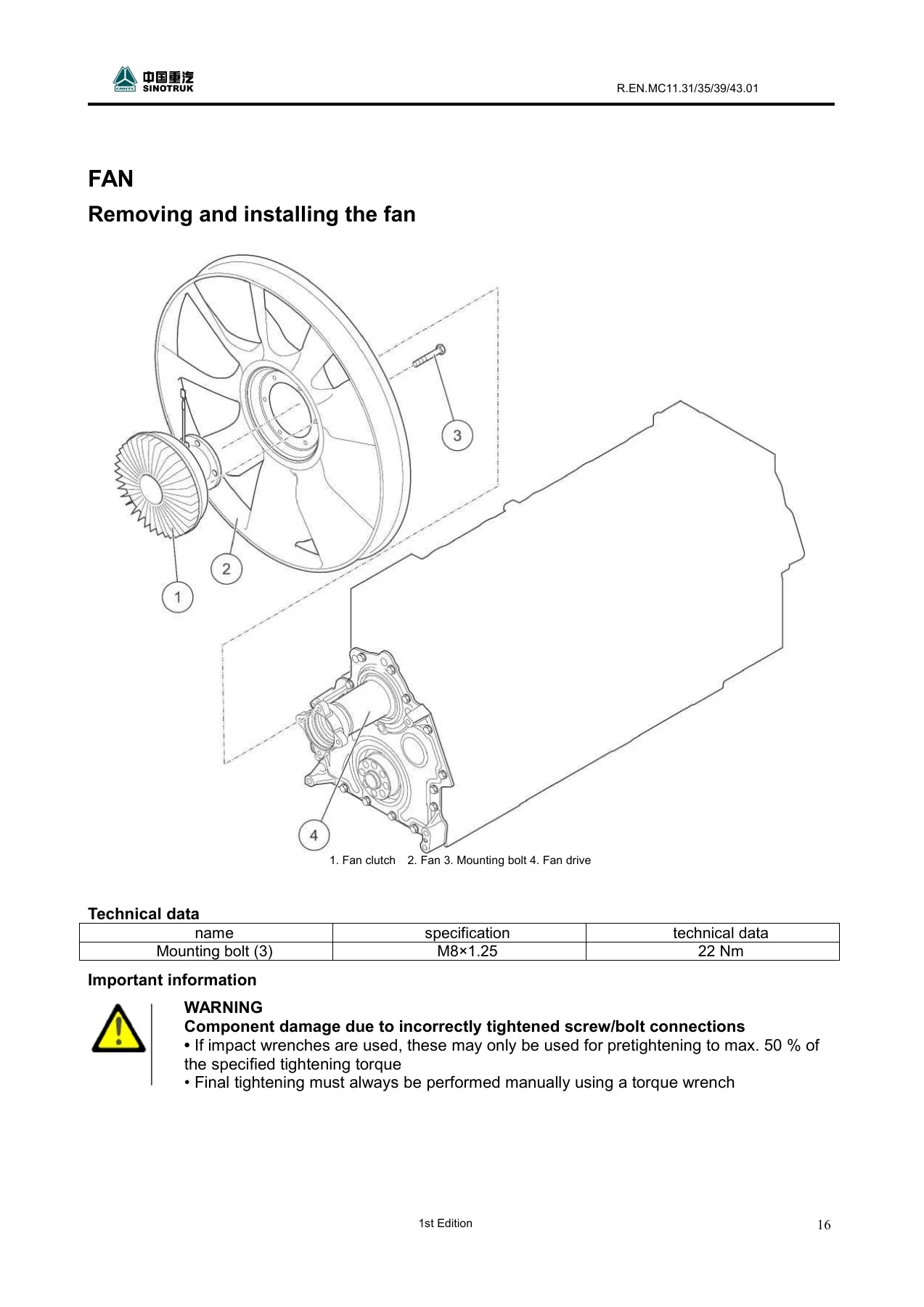
All of the front-end cooling hardware is here: the fan (704 mm or 750 mm diameter), the viscous fan clutch, and the fan drive with its axial play limit of 0.20-0.55 mm and radial play limit of 0.035-0.076 mm measured with a dial gauge on the fan hub. The coolant manifold, the 83 degrees C thermostats and their housing, the coolant pump, and the distributor housing that carries the pump, alternator and refrigerant compressor are each given their own removal and installation sequence with O-ring and seal handling notes.
Mounted Components
The single-cylinder air compressor, the 5.5 kW 24 V starter, the poly-V belt drive with its spring-loaded tensioner and reversing rollers, and the alternator. Belt tensioner work carries an explicit caution – the tensioner is under spring tension and must be held steady so it does not spring back. The alternator section also includes the special spanner and gripper procedure for undoing the poly-V pulley mounting nut at 80-100 Nm.
Intake/Exhaust System and Turbocharger
The three-section exhaust manifold with its multi-piece rings set at 90 degrees apart, the heat shields, the charge-air pipes and manifold, and the turbocharger. Turbocharger mounting nuts are M10 at an initial 10 Nm then 90 degrees, and there is a warning that the turbo must be primed with clean engine oil through the oil feed neck before the oil pressure line is attached, otherwise it will be damaged on first start-up.
Cylinder Head and Valve Train
The cylinder head chapter is one of the deepest in the book. It carries the full 26-bolt tightening sequence, the staged torque values of 10 Nm, 150 Nm and 300 Nm followed by three 90 degree turns, the requirement not to reuse old cylinder head bolts even after one use, and the White T assembly paste instruction for the bolt support surface. Cylinder liner protrusion is checked at 0.035-0.085 mm before the head goes back on. Valve clearance setting follows the rocker-arm overlap table with intake at 0.5+/-0.03 mm, exhaust at 0.8+/-0.03 mm and EVB counter-holder clearance at 0.6+/-0.03 mm, all adjusted cold. Valve stem seals are colour-coded – green for intake, brown for exhaust – and the valve spring compressor procedure is covered with the holders and adapters needed.
Camshaft, Valve Timing and Timing Gears
Camshaft axial play is quoted at 0.05-0.85 mm and radial play at 0.024-0.090 mm, with checks on the bearing shell inside diameter, the bearing shell spread and the camshaft gear installation depth. Valve timing verification uses a dial gauge on the third-cylinder intake valve disc with a specified lift window. The rear timing gear chapter covers the rear crankshaft gear, the large and small intermediate gears and the split, preloaded air compressor intermediate gear, with backlash values for each mesh and a warning that the thrust washer can fall into the oil sump during removal.
Common-Rail System
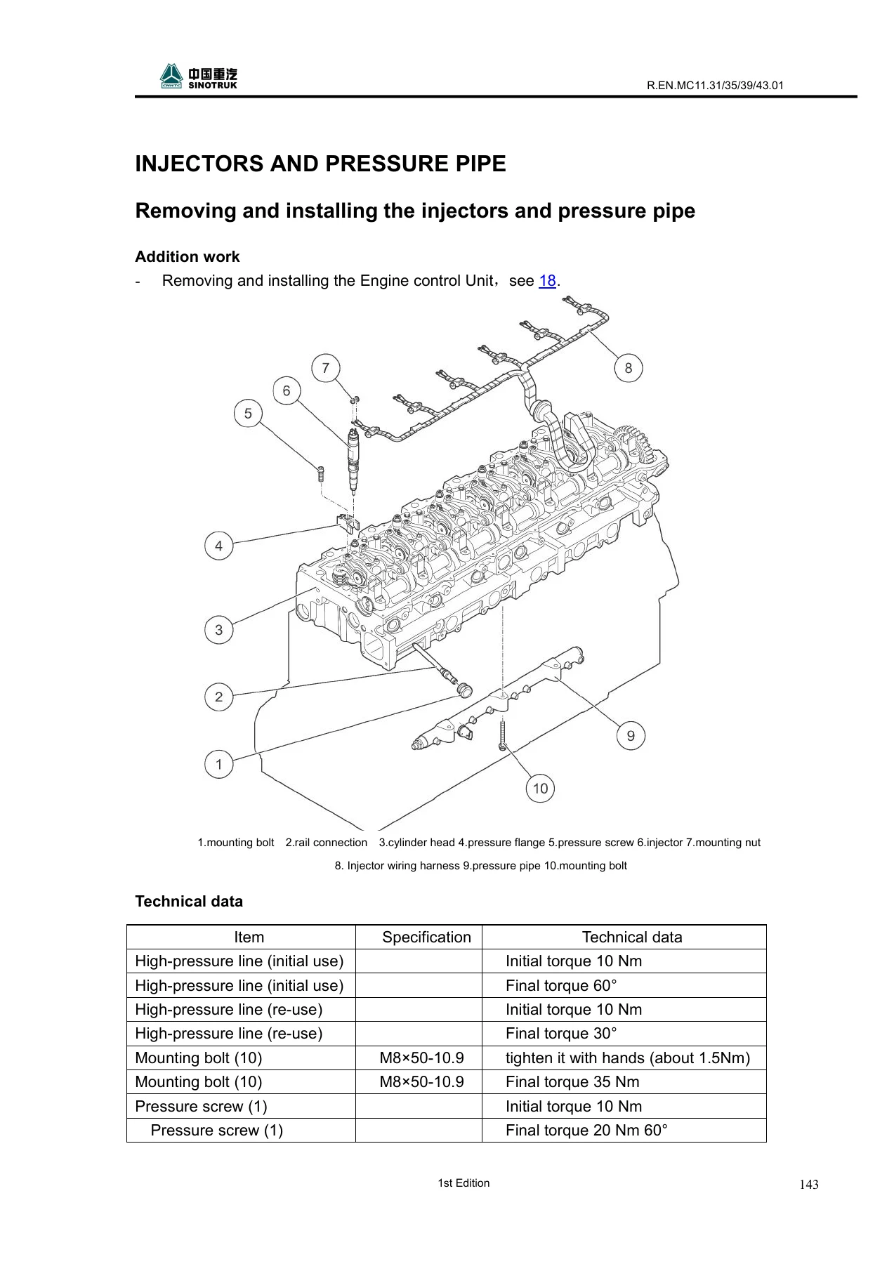
Injector removal uses a puller and plate assembly, and the manual is emphatic that rail connections are single-use – once a rail connection has been undone it must be renewed, and the same applies to high-pressure lines and plugs. Tightening values are split between first fit and reuse: high-pressure lines go to 10 Nm then 60 degrees when new, or 30 degrees if reusing, and the injector pressure flange mounting bolt runs 1-2 Nm initial then 25 Nm plus 90 degrees final. The high-pressure pump is torqued to 60-70 Nm, the pump drive to 115 Nm, the rail pressure sensor to 70+/-5 Nm and the pressure limiting valve to 100+/-5 Nm – with a warning not to wash off the lubricant coating on those two components. The fuel service centre chapter covers the filter and pre-filter, the hand pump housing, the heating element, the pressure sensor and the drain plug torque values.
Engine Lubrication
The oil module is handled as a complete assembly with the oil cooler, filter cover and oil separator, and the manual warns that coolant must be drained before removal or coolant will enter the oil sump. The pressure-relief valve is torqued to 45 Nm, the oil filter cover to 40+10 Nm, the oil sump and suction pipe have their own stiffening plate and spacer-sleeve sequence, the oil injector nozzles are 15 Nm, and the oil pump chapter gives ring gear axial play at 0.020-0.093 mm and radial play at 0.053-0.210 mm along with the bearing bush extraction and press-in procedure.
Crankshaft Oil Seals, Engine Housing, Pistons, Crankshaft and Front Drive Gears
The two crankshaft oil seals have their own special tool sets and a clear PTFE warning: the seal is unusable if it contacts oil or grease before installation, so the crankshaft and insertion tool must be clean. The engine housing chapter covers the flywheel housing/timing case, the front cover, the cylinder liners, pistons and connecting rods, the vibration damper, the flywheel, the crankshaft and the front drive gears. Key values include the vibration damper mounting bolt at M16x85-10.9 initial 150+10 Nm then 90+10 degrees, the flywheel bolt at M16x1.5×81-12.9 initial 100+10 Nm then 180+10 degrees, and the crankshaft bearing cap bolts at 50 Nm, 150 Nm, 300 Nm then 90+10 degrees. The cracked connecting rods carry a repeated warning – the crack surfaces are sensitive and the rod must be exchanged if they are damaged.
Technical Data
The rear of the manual is a consolidated data section: a torque and tighten-angle summary covering 47 fastener groups, a fit and clearance summary covering 63 dimensions – main and connecting rod bearing clearances, gear backlash values for every mesh in the front and rear trains, oil pump rotor clearances, valve timing events and valve recess quantities – and a gluing summary identifying where Loctite 5900, Loctite 243, Loctite 2701 and White T paste are used.
What This MC11 Euro III Service Manual Lets You Do
This is the manual you reach for when the job is not a guess. Pulling an injector on a common-rail MC11 without the right puller and the single-use rail connection rule will cost you a cylinder head; setting valve clearance on a warm engine will cost you a warranty claim; reusing cylinder head bolts will cost you a gasket. Every one of those traps is documented here, with the exact torque, angle, clearance and special tool code you need to do it correctly the first time. It supports full engine-out overhauls as well as day-to-day work – fan drive play checks, thermostat replacement, air compressor swaps, alternator pulley work, oil module and cooler service, injector and high-pressure pump replacement, cylinder head removal, timing gear inspection and crankshaft and piston work. If you maintain or rebuild SINOTRUK MC11.43, MC11.39, MC11.35 or MC11.31 engines, this Sinotruk MC11 Euro III engine repair manual is the reference that keeps the torque wrench honest.
IMAGES PREVIEW
Instant PDF Delivery
Delivered as a 273-page PDF the moment payment clears – no shipping, no waiting on a courier, no torn paper manual in the workshop. Open it on a laptop on the bench, a tablet on the wing, or a phone under the truck, and print only the pages you need for the job in front of you. The MC11 Euro III workshop PDF stays searchable on your own device and can be re-downloaded whenever you need it.
Reviews
There are no reviews yet.