SKF Infinity Blasthole Drill Service Manual Cat Rotary Track Drill SN 2E68F05 – PDF DOWNLOAD
Original price was: $98.95.$38.95Current price is: $38.95.
SKF Infinity Blasthole Drill Service Manual Cat Rotary Track Drill SN 2E68F05 – PDF DOWNLOAD
Description
SKF Infinity Blasthole Drill Service Manual Cat Rotary Track Drill SN 2E68F05 – PDF DOWNLOAD
SKF INFINITY BLASTHOLE DRILL SERVICE MANUAL CAT ROTARY TRACK DRILL SN 2E68F05 – PDF DOWNLOAD:
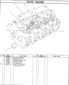
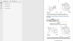
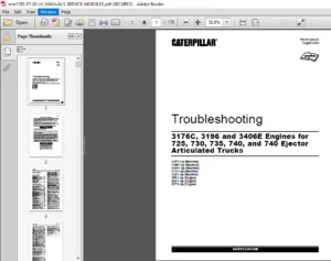
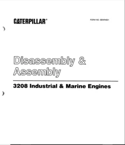
IMAGES PREVIEW OF THE MANUAL:


DESCRIPTION:
SKF Infinity Blasthole Drill Service Manual Cat Rotary Track Drill SN 2E68F05 – PDF DOWNLOAD
Safety Information :
This manual is furnished with your Infinity Series rotary blasthole drill to aid you in performing the necessary service work to maintain your drill in good operating condition. This manual contains repair and adjustment information for all major operating systems on the machine. In some cases such as hydraulic pumps and motors it is better to replace the unit with a new or rebuilt unit than to perform major repairs. Should further information be desired or should particular problems arise which are not covered sufficiently in this manual, the matter should be referred to manufacturer.
- The descriptions and specifications contained in this manual were in effect at the time of printing. The right is reserved to make changes at any time without notice and without obligation. It is YOUR responsibility to understand and follow manufacturer’s instructions on machine operation and service, and to observe pertinent safety precautions, laws and regulations. Failure to read and understand this manual and all safety, capacity and instruction placards on the machine before operating the unit, constitutes a misuse of the machine.
- It is your responsibility to know the manufacturer’s specific requirements, government regulations, required precautions and any work hazards which may exist. You must make these known to all personnel working with the equipment or in the area, so that all may take the necessary and required safety precautions.
- Keep all children, visitors, and untrained personnel away from the equipment. It is also your responsibility to operate your equipment with skill, good judgment, and caution. Following recognised safety procedures will help you avoid accidents. Failure to heed these instructions can result in property damage, serious injury or death.
TABLE OF CONTENTS:
SKF Infinity Blasthole Drill Service Manual Cat Rotary Track Drill SN 2E68F05 – PDF DOWNLOAD
SKF Infinity Blasthole Drill Serial No. 2E68F05 Service Manual.....................................................  1
	Parts Ordering and Product Support.............................................................................  3
	Safety Information.............................................................................................  4
	Contents.......................................................................................................  5
		Section 1 – Safety.........................................................................................  5
		Section 2 - Operator's Cab / Controls......................................................................  5
		Section 3 - Main Frame / Crawlers..........................................................................  6
		Section 4 - Engine / Drive Train / Compressor..............................................................  8
		Section 5 - Dust Control System............................................................................ 10
		Section 6 - Mast / Rotary Drive / Pipe Rack................................................................ 11
		Section 7 - Hydraulic Systems.............................................................................. 12
		Section 8 - Electrical components.......................................................................... 15
		Section 9 - Lubrication and Preventive Maintenance......................................................... 15
	General Locator................................................................................................ 18
		Rear and Right Hand Side View.............................................................................. 18
		Front and Left Hand Side................................................................................... 19
		Overview................................................................................................... 20
	Notes.......................................................................................................... 21
	Section 1 Safety............................................................................................... 23
		Contents................................................................................................... 25
			Page 1-3............................................................................................... 25
		Safety..................................................................................................... 27
			Overview	of	Potential	Hazards.......................................................................... 27
			Personal	Protective	Equipment.......................................................................... 27
			Noise.................................................................................................. 27
			Electrical	Contact..................................................................................... 27
			Contaminated Air....................................................................................... 28
			Moving	and	Rotating	Parts.............................................................................. 29
			High	Pressure	Air	or	Fluid............................................................................. 29
			Before Operation....................................................................................... 29
			During	Operation....................................................................................... 30
			Maintenance............................................................................................ 32
			Equipment	Transfer..................................................................................... 32
			Safety	Locator......................................................................................... 33
				Right Side View.................................................................................... 33
				Front and Left side View........................................................................... 34
				Over View.......................................................................................... 35
		Notes...................................................................................................... 36
	Section 2 Operators Cab / Controls............................................................................. 37
		Contents................................................................................................... 39
			Page 2-3............................................................................................... 39
		Graphic Symbol Legend...................................................................................... 41
			Graphic	Symbol	Legend.................................................................................. 41
		Warning Decals............................................................................................. 45
			Warning	Decals......................................................................................... 45
		Operator Control and Instrument Panels..................................................................... 48
			Control Panels......................................................................................... 48
			Right	Hand	Control	Panel............................................................................... 48
			Instrument Panel....................................................................................... 50
			Circuit Breakers....................................................................................... 51
			Light	Switches......................................................................................... 51
			System	Pressure	Gauge	Panel............................................................................ 52
			Left	Hand	Control	Panels............................................................................... 54
			Cab Foot Controls...................................................................................... 58
			Thread	Grease	Switch................................................................................... 58
			Pipe	Safety	Arm	Override	Switch........................................................................ 58
		Machine Stability.......................................................................................... 59
			Tramming	Procedure..................................................................................... 59
			Track Adjustments...................................................................................... 59
			New Machine Procedure.................................................................................. 60
			General	Maintenance	Checks	While	Tramming.............................................................. 60
			Roller	Locations....................................................................................... 61
			Temperature	and	Condition	Record	Chart	for	Walking..................................................... 62
			Propelling	the	Machine................................................................................. 63
			Stability	Limits....................................................................................... 65
			SKF	Transient	Stability	Limits......................................................................... 66
		Cab Heater................................................................................................. 67
			Cab	Heater	Fault	Isolation............................................................................. 67
		T8	Series	Split	System	Air	Conditioning.................................................................... 68
			Section		1.0	Technical	Data	and	Control	Settings....................................................... 69
			Section	2.0	Installation	and	Commissioning............................................................. 71
			Section	3.0		Routine	Maintenance	Procedures............................................................ 75
			Section	4.0	Fault	Diagnosis............................................................................ 76
			Section		5.0	Reference	Drawings........................................................................ 85
		Notes...................................................................................................... 91
	Section 3 Main Frame / Crawlers................................................................................ 93
		Contents................................................................................................... 95
			Page 3-3............................................................................................... 95
			Page 3-4............................................................................................... 96
		Main Frame Repair - General................................................................................ 97
			Main Frame Repair...................................................................................... 97
		Weld Inspection Schedule................................................................................... 98
			Main Frame............................................................................................. 98
		Levelling Jacks............................................................................................ 99
			Levelling	Jack	Cylinder................................................................................ 99
			Levelling	Jacks........................................................................................100
			Limit	Switch...........................................................................................100
			Levelling	Jack	Cylinders...............................................................................100
		Mast Elevating Cylinders...................................................................................101
			Mast	Elevating	Cylinders...............................................................................101
			Internal	Counterbalance	Valve..........................................................................102
		Fuelling Valves............................................................................................104
			Hydrau-Flo®	Fuelling	Valves............................................................................104
		Crawler Assembly...........................................................................................106
			Crawler	Assembly.......................................................................................106
			Crawler Component Repair...............................................................................107
		Tramming...................................................................................................108
			Maintenance Checks	for	Tramming........................................................................108
			Track	Adjustments......................................................................................108
			New Machine Procedure..................................................................................109
			General	Maintenance	Checks	While	Tramming..............................................................109
			Roller Locations.......................................................................................110
			Temperature	and	Condition	Record	Chart	for	Walking.....................................................111
		Metric Bolt Torque.........................................................................................112
			Metric	Bolt	Torque	Specification.......................................................................112
		Track Maintenance..........................................................................................113
			Before	Operating	the	Machine...........................................................................113
			General Maintenance....................................................................................113
		Track Tension..............................................................................................114
			Track	Assembly.........................................................................................114
			Hydraulic Tensioner....................................................................................116
			Track	Tension	Unit.....................................................................................117
		Track and Support Rollers..................................................................................118
			Track	Roller...........................................................................................118
			Track	Roller	Unit......................................................................................119
			Track	Roller	–	Assembly................................................................................120
			Track	Roller	–	Test	and	Install........................................................................121
			Support	Roller.........................................................................................123
		Track Chain................................................................................................127
			Track	Chain............................................................................................127
		Track Shoes Installation...................................................................................130
			Track	Link	Position....................................................................................130
			Track	Shoe	–	Mounting	to	Track	Chain...................................................................130
		Track Shoe bolt Torque (Direct Torque Method)..............................................................132
			Bolt	Torque	KN111......................................................................................132
		Track Shoe bolt Torque (Torque Turn Method)................................................................133
			Bolt	Torque	KN111......................................................................................133
		Track Chain and Shoe Installation..........................................................................134
			Track	Chain	with	Shoes.................................................................................134
		Final Drive Unit...........................................................................................136
			Final	Drive	Unit.......................................................................................136
			Removal	from	Track	Frame...............................................................................137
			Installation	into	Track	Frame..........................................................................138
			Final	Drive	Maintenance................................................................................139
			Final	Drive	Oil........................................................................................140
			Final	Drive	Assembly...................................................................................142
			Parking	Brake	–	Description............................................................................143
			General Description....................................................................................144
			General	Recommendations	for	Disassembly	and	Assembly	Operations........................................144
			Final Drive –	Disconnect and Parking Brake.............................................................146
			Towing	Procedure	–	Gear	Drive	Disconnect...............................................................146
			Parking	Brake	–	Description............................................................................147
			Untitled...............................................................................................147
			Sealing	Compounds	and	Adhesives........................................................................148
			Filling	and	Checks.....................................................................................150
			Service	Schedule.......................................................................................150
			Tightening	Torques.....................................................................................151
			Lubrication	/	Greasing	– Grades	and	Application	Range..................................................151
			Troubleshooting........................................................................................152
			Special	Tools..........................................................................................152
		Idler Unit.................................................................................................153
			Idler Unit.............................................................................................153
		Track and Sprocket Inspection..............................................................................157
			Track	Inspection	and	Wear	Limit	Guide..................................................................157
			Sprocket	Wear	Patterns.................................................................................162
		Auxiliary Crane............................................................................................168
			Hydraulic	Crane	–	Rear	Deck	Crane	Palfinge	PC1500......................................................168
			Rear	Deck	Crane	Palfinge	PC1500	Service	Information....................................................169
			Checking	Bolted	Connections............................................................................169
			Maintenance Chart......................................................................................170
			Lubrication............................................................................................172
			Hydraulic Fluids.......................................................................................175
			Oil	Change	/	Oil	Maintenance...........................................................................176
			Cleaning	Agents	and	Equipment..........................................................................176
			Repairing	Paint	Damage.................................................................................177
			Removal	From	Service	and	Disposal......................................................................177
		Notes......................................................................................................178
	Section 4 Engine / Drive Train / Compressor....................................................................179
		Contents...................................................................................................181
			Page 4-3...............................................................................................181
			Page 4-4...............................................................................................182
		Power Group Locator........................................................................................183
			Power Group Locator....................................................................................183
		Test Point Locator.........................................................................................184
			Test Point Locator.....................................................................................184
		Engine.....................................................................................................186
			Cummins Engine.........................................................................................186
			Oil Reserve Systems....................................................................................187
			LED Monitor Readings...................................................................................188
			Adjustment of Running Oil Level........................................................................188
			Wiring Diagram – Oil Reserve Basic Circuit.............................................................189
			Oil Pressure Switch....................................................................................189
			Oil Reserve System.....................................................................................189
			Troubleshooting........................................................................................190
			Maintenance............................................................................................190
			Engine Fuel System – QSK19 Tier II.....................................................................191
			Filtration Hardware Mounting...........................................................................195
			Fuel Plumbing..........................................................................................195
			Installation Requirements..............................................................................196
			Installation and Operation Recommendations.............................................................196
			Fuel Filter (Stage 1)..................................................................................198
			Fuel Filter (Stage 2)..................................................................................202
		Engine and Compressor Air Cleaners.........................................................................205
			Engine and Compressor Air Cleaner Service Assembly.....................................................205
			Engine and Compressor Air Cleaner Service..............................................................206
		Flexible Drive Coupling....................................................................................209
			Flexible Drive Coupling Service........................................................................209
		Pump Drive.................................................................................................211
			Pump Drive Assembly – Removal and Replacement..........................................................211
			Pump Drive Gearbox.....................................................................................212
			Pump Drive Gearbox – Repair............................................................................212
		Hydraulic Pumps............................................................................................214
			Pump Arrangement.......................................................................................214
			Hydraulic Pumps – Removal and Replacement..............................................................215
		Compressor Installation....................................................................................216
			1700cfm / 100psi Compressor Assembly...................................................................216
			Safety.................................................................................................217
			Compressor Installation................................................................................220
			Compressor Drive Coupling..............................................................................221
			Compressor Alignment...................................................................................222
			Mounting	Instructions	for	Arcusaflex	Flywheel	Couplings................................................223
			Taper-Loc	Bushing	Installation	–	Model	AC-T5.SN.	F2.	V1.	3535..........................................224
			Tightening	Torques	for	Arcusaflex	Flywheel	Couplings...................................................224
		Compressor Shaft Seal......................................................................................225
			Compressor Shaft Seal..................................................................................225
		Low Pressure Compressor....................................................................................227
			Description............................................................................................227
			Compressed Air Functions...............................................................................227
			Compressor Inlet Valve Control System..................................................................231
			nlet Valve.............................................................................................232
			Compressor Regulation..................................................................................234
			Relieving Regulators...................................................................................235
			Reducing Regulators....................................................................................237
			System Blowdown Valve..................................................................................239
			Running Blowdown Valve.................................................................................240
			Spiral Valve...........................................................................................242
			Compressor Air and Oil Circuits – 1700cfm @ 100psi.....................................................242
			Compressor Air Circuit Parts List......................................................................245
			Compressor Air Circuit Legend..........................................................................245
			Compressor Control Set-up Vented Poppet Inlet – Shutdown...............................................246
			Compressor Control Set-up Vented Poppet Inlet – Initial Start-up Below 50psi...........................247
			Compressor Control Set-up Vented Poppet Inlet – Initial Start-up Above 50psi...........................248
			Compressor Control Set-up Vented Poppet Inlet – Run Unloaded...........................................249
			Compressor Control Set-up Vented Poppet Inlet – Drilling...............................................250
			Compressor Control Set-up Vented Poppet Inlet – Shutting Down..........................................251
			Operation..............................................................................................252
		Compressor Maintenance.....................................................................................254
			General Maintenance....................................................................................254
			Discharge Check Valve..................................................................................256
			Compressor Receiver Tank Assembly......................................................................257
			Separator Elements.....................................................................................258
			Scavenge Line..........................................................................................259
			Compressor Discharge Temperature Gauge, Switch and Sender..............................................261
			Minimum Pressure Valve.................................................................................262
			Minimum Pressure / Check Valve Maintenance.............................................................262
			Thermal Bypass Valve...................................................................................263
			Thermal Bypass Valve Maintenance.......................................................................264
			Compressor Fluid Filter................................................................................266
			Changing Filter Elements...............................................................................267
			Oil Stop Valve.........................................................................................268
			Troubleshooting........................................................................................269
		Coolers....................................................................................................271
			Hydraulic Oil / Radiator Cooler Assembly...............................................................271
			Compressor Oil Cooler..................................................................................272
			Fan Speed..............................................................................................272
			Engine Cooler / Radiator...............................................................................273
		Aluminium Tube Air to Oil Cooler...........................................................................274
			Aluminium Tube Air to Oil Cooler – Standard Parts......................................................274
			Removal and Replacement................................................................................275
			Internal Cleaning......................................................................................277
		Radiator Cooler............................................................................................279
			Typical Radiator Core – Standard Parts.................................................................279
			Cleaning...............................................................................................280
			Tube Removal...........................................................................................281
			Seal Installation......................................................................................282
			Lubricating Seals and Tube Ends........................................................................282
			Tube Installation......................................................................................283
		Notes......................................................................................................286
	Section 5 Dust Control System..................................................................................287
		Contents...................................................................................................289
			Page 5-3...............................................................................................289
		Dust Control System........................................................................................291
			Dust Control Systems...................................................................................291
		Water Injection............................................................................................293
			Water Tanks............................................................................................293
			Water Injection Pump...................................................................................294
			Water	Injection	Relief	Valve...........................................................................294
			Water Injection Control................................................................................295
			Water Injection Basic Circuit..........................................................................297
		Water Pump.................................................................................................298
			Water	Injection	Pump	Assembly..........................................................................298
			Pump	Specification.....................................................................................299
			Torque Requirements....................................................................................299
			Servicing	Instructions.................................................................................299
			Servicing	the	Plunger	Packings.........................................................................299
			Reassembling	Plunger	Packings..........................................................................300
			Servicing	the	Pump	Valves..............................................................................300
			Reassembling	Valve	Parts...............................................................................300
			Servicing	the	Crankshaft...............................................................................301
			Servicing	the	Crossheads...............................................................................301
			Replacing	Piston	Cup	Seals.............................................................................302
			Replacing	Suction	and	Discharge	Valves.................................................................303
			Replacing	Power	End	Bearings...........................................................................304
			Servicing	the	Wrist	Pin	Bearings.......................................................................305
			Fastener	Torque	Requirements...........................................................................305
			Recommended	Lubricants.................................................................................306
			Water Pump Motor Repair................................................................................306
			Water	Pump	Drive	Coupling..............................................................................306
			Level	and	Flow	Transducer..............................................................................306
		Notes......................................................................................................307
	Section 6 Mast / Rotary Drive / Pipe Rack......................................................................309
		Contents...................................................................................................311
			Page 6-3...............................................................................................311
			Page 6-4...............................................................................................312
		Mast Weldment..............................................................................................313
			Mast Repair............................................................................................313
		Weld Inspection Schedule...................................................................................314
			Mast Inspection........................................................................................314
		Mast Assembly and Installation.............................................................................315
			Mast	Assembly..........................................................................................315
			Mast Pivot Caps........................................................................................316
			Mast	Elevate	Cylinders.................................................................................317
			Angle	Drilling.........................................................................................317
			Mast / Drill Without Mast..............................................................................318
			Mast	Assembly..........................................................................................319
			Raising	the	Mast.......................................................................................319
		Hoist / Pulldown Cylinder..................................................................................321
			Hoist / Pulldown Cylinder..............................................................................321
			Feed	Cylinder	System...................................................................................322
			Removal................................................................................................323
			Installation...........................................................................................324
			Repair.................................................................................................325
			General Information....................................................................................325
		Hoist / Pulldown Cable.....................................................................................326
			Hoist	/	Pulldown	Cable	Adjustment......................................................................326
			Hoist	/	Pulldown	Cable	Replacement.....................................................................327
			Wire Rope..............................................................................................328
		Rotary Drive...............................................................................................329
			Alignment	Procedure....................................................................................329
			Rotary	Drive	Assembly..................................................................................330
			Rotary Drive – Removal from Mast.......................................................................331
			Rotary Drive – Installation............................................................................331
			Single	Motor	Rotary	Drive	Gearbox......................................................................332
			Manufacturers	Recommendations	–	Blast	Hole	Drilling	Consumables	.......................................333
			Air	Swivel	(Single	Seal	Style).........................................................................334
			Rotary Drive Motor – Repair............................................................................335
			Torque	Limit	Table	Grade	8	UNC.........................................................................336
			Torque	Limit	Table	Grade	8	UNF.........................................................................337
			Rotary Drive Motor.....................................................................................338
		Deck Wrench................................................................................................339
			Deck Wrench............................................................................................339
		H.O.B.O Wrench.............................................................................................340
			H.O.B.O	Wrench.........................................................................................340
			Tong	Dies..............................................................................................341
			Optional	Hydraulic	Operated	Bit	Basket	–	H.O.B.B.......................................................342
		Pipe Positioner............................................................................................343
			Pipe Positioner........................................................................................343
		Carousel Pipe Rack.........................................................................................344
			Carousel Pipe Rack.....................................................................................344
			Chain Drive – adjustment / Replace.....................................................................344
			Pipe	Rack	Bearings	–	Replace...........................................................................345
			Carousel	Top	Tube	Bearing	–	Replace....................................................................346
			Carousel	Lower	Bearing	–	Replace.......................................................................348
			Upper	Pivot	Support	Bearing............................................................................349
			Carousel	Pivot	Support	Upper	Bearing	–	Replace.........................................................350
			Pivot	Support	Pipe	Lower	Bushing.......................................................................351
			Carousel	Pivot	Support	Lower	Bearing	–	Replace.........................................................352
			Mid	Point	Carousel	Pivot	Support.......................................................................353
			Carousel Rotate Motor..................................................................................353
		Top Sub Saver..............................................................................................354
			Replacement Procedure..................................................................................354
		Notes......................................................................................................355
	Section 7 Hydraulic Systems....................................................................................357
		Contents...................................................................................................359
			Page 7-3...............................................................................................359
			Page 7-4...............................................................................................360
			Page 7-5...............................................................................................361
		Hydraulic Symbols..........................................................................................363
			Hydraulic	Symbols......................................................................................363
		Pressure Setting Sequence..................................................................................365
			Pressure	Setting	Sequence..............................................................................365
			Hydraulic System.......................................................................................365
		Main Hydraulic Pumps.......................................................................................366
			Pump	Arrangement.......................................................................................366
		Hydraulic Tank.............................................................................................367
			Hydraulic	Tank.........................................................................................367
			Hydraulic System.......................................................................................368
		Main Return and Case Drain Filter..........................................................................369
			Routine Maintenance....................................................................................370
			Changing	Filter	Elements...............................................................................370
		Loop Filters...............................................................................................371
			Loop	Filters...........................................................................................371
			Loop	Filter Cross Section..............................................................................372
			Filter	Assembly	Loop...................................................................................373
			Changing	Filter	Elements...............................................................................374
		Charge Circuit.............................................................................................375
			Routine Maintenance....................................................................................375
			Changing	Filter	Elements...............................................................................376
			Charge	Pressure........................................................................................377
			Set	Charge	Pressure	–	350psi	(24bar)...................................................................377
			Charge	Pumps...........................................................................................378
		Main Pumps Circuit.........................................................................................379
			Main Pumps circuit.....................................................................................379
		Right Track / Left Track / Rotation Pumps..................................................................380
			Linde HPV-02 Bi-directional Variable Displacement Closed Loop Pump.....................................380
			Dimensions.............................................................................................382
			Operational Parameters.................................................................................383
			Controls...............................................................................................384
			Hydraulic	Piston	Pumps	–	Removal	and	Replacement.......................................................387
			Main Pumps.............................................................................................387
			EP	(24V	DC)	Control....................................................................................387
			Main	Pump	Adjustments..................................................................................388
			Technical Data.........................................................................................389
			Setting	Linde	HPV-02	Main	Pumps	–	Neutral		Setting.....................................................390
			Setting	Linde	HPV-02	Main	Pumps	–	Pressure	Settings....................................................391
			Setting	Linde	HPV-02	Main	Pumps	–	Pre-setup	Checks.....................................................392
			Main	Pumps	Linde	HPV-02................................................................................393
			Setting	Procedure......................................................................................394
		Diverter Valve.............................................................................................395
			Closed Loop Pump circuit...............................................................................395
			Operation..............................................................................................395
			Diverter	Valve.........................................................................................395
		Rotation Circuit...........................................................................................396
			Basic	Rotation	Circuit.................................................................................396
			Rotation circuit.......................................................................................397
		Tram Circuit...............................................................................................398
			Tram circuit	–	Two	Speed...............................................................................398
			Brake	Test	Procedure...................................................................................399
		Rotary Drive Gearbox Motor.................................................................................400
			Variable	Displacement	Rotation	Motor...................................................................400
		Pilot Control Manifold.....................................................................................404
			Pilot control Manifold.................................................................................404
			Pilot	Control	Manifold	Assembly........................................................................405
			Control	Valve	Assembly.................................................................................406
			Electro	Proportional	Valves............................................................................413
			Proportional	Valve	Set-up..............................................................................414
			Auto Pulldown Card.....................................................................................414
			Torque Control.........................................................................................415
			Proportional Pulldown..................................................................................416
			OEM	Controllers	/	EP	Levers............................................................................417
		Auxiliary Pump Circuit.....................................................................................418
			Feed	and	Auxiliary	Pump	Circuit........................................................................418
			Linde	HPR-02	Self-Regulating	Pump......................................................................419
			Feed	and	Auxiliary	Functions	Pump......................................................................420
			Linde	HPR-02	Self-Regulating	Pump......................................................................421
			Hydraulic	Piston	Pumps	–	Removal	and	Replacement.......................................................423
		Auxiliary Circuit..........................................................................................424
			Auxiliary	Circuit	Functions............................................................................424
			Auxiliary	Valves.......................................................................................426
		Jack Control and Mast Elevating Circuit....................................................................429
			Jack	Control	and	Mast	Elevating	Circuit	Schematic......................................................429
			Jack	Control	and	Mast	Elevating	Control	Valve..........................................................430
			Jack	Control	and	Mast	Elevating	Circuit................................................................431
		Counterbalance Valves......................................................................................432
			Counterbalance	Valve	Adjustments.......................................................................432
			Internal	Counterbalance	Valve..........................................................................433
		Levelling Jack Cylinders...................................................................................435
			Jack	Leg	Cylinder......................................................................................435
			Counterbalance	Valve	Test	Procedure....................................................................435
		Mast Elevating Cylinders...................................................................................436
			Mast	Elevating	Cylinders...............................................................................436
		Hydraulic Operated Breakout Wrench.........................................................................437
			H.O.B.O	Wrench.........................................................................................437
			etting	of	H.O.B.O	Sequence	Valves......................................................................438
			H.O.B.O	Float	Valve....................................................................................438
		Hydraulic Feed Circuit.....................................................................................439
			Hydraulic	Feed	Circuit.................................................................................439
		Hoist and Pulldown Control.................................................................................441
			Directional	Control	Valve	MP22.........................................................................441
		Feed Valve Assembly........................................................................................443
			Feed Valve Assembly....................................................................................443
		Control Valve Assembly.....................................................................................445
			Technical Data.........................................................................................445
		Cooler Fan Circuit.........................................................................................447
			Cooler	Fan	Circuit.....................................................................................447
			Setting	Cooler	Fan	Speed...............................................................................447
			Hydraulic Cooler	–	Thermal	Valve.......................................................................448
			Basic	Cooler	Fan	Circuit...............................................................................449
		Cooler Fan Motor...........................................................................................450
			Cooler	Fan	Motor	Assembly..............................................................................450
			Hydraulic Motor........................................................................................451
		Water Pump Motor...........................................................................................454
			Water Pump Motor Repair Information....................................................................454
			Shaft Seal Repair......................................................................................455
		Hydraulic Cylinder Repair..................................................................................458
			Hydraulic Cylinders....................................................................................458
			General Information....................................................................................459
			H Head.................................................................................................461
			N Head.................................................................................................462
			Z	Head.................................................................................................463
			Z	Head	(Two	Piece).....................................................................................464
			K	Head.................................................................................................465
			M Head.................................................................................................466
			Z	Piston...............................................................................................467
			Z	Piston	(Threaded)....................................................................................468
			H	and	K	Piston.........................................................................................469
			M Piston...............................................................................................470
			N Piston...............................................................................................473
		Hydraulic Systems..........................................................................................474
			Main Hydraulic Schematic...............................................................................474
		Notes......................................................................................................475
	Section 8 Electrical Components................................................................................477
		Contents...................................................................................................479
			Page 8-3...............................................................................................479
		Electrical Locator.........................................................................................481
			Electrical Component Location..........................................................................481
		Jump Starting..............................................................................................484
			Jump	Starting..........................................................................................484
		Batteries..................................................................................................486
			Batteries..............................................................................................486
		Welding Precautions........................................................................................487
			Welding	Precautions....................................................................................487
		Electrical Components......................................................................................488
			Electrical Circuits....................................................................................488
			Transducers............................................................................................488
			EP	Levers..............................................................................................489
			Joystick	Adjustments...................................................................................490
		Vigilante Guide............................................................................................492
			Important Information..................................................................................492
			PLC....................................................................................................493
			Touchscreen............................................................................................496
			Laser	Depth	System.....................................................................................497
			Distance Meter.........................................................................................500
			Start-up	and	Shutdown..................................................................................500
			Hydraulic	Function	Enable..............................................................................500
			Alarms.................................................................................................501
			Solenoid	Control.......................................................................................501
			Auto	Lube..............................................................................................504
			Gauges.................................................................................................504
			Level	Switches.........................................................................................506
			Head	Speed	Module......................................................................................507
			Dust	Suppression.......................................................................................508
			Acknowledgements.......................................................................................508
			Disclaimers............................................................................................509
		Notes......................................................................................................510
	Section 9 Lubrication and Preventive Maintenance...............................................................511
		Contents...................................................................................................513
			Page 9-3...............................................................................................513
			Page 9-4...............................................................................................514
		Central Lube System........................................................................................515
			Auto	Lube	Basic	Operation..............................................................................515
			Central	Lube	Tank	Assembly.............................................................................516
			Auto	Lube	Grease	Pump..................................................................................517
			Auto Lube Tube Pump....................................................................................523
			Graco	Vent	Valve.......................................................................................528
			Central	Lube	System	Circuit............................................................................529
			Basic	Operating	Principles	of	Auto	Lube	Injectors......................................................530
			SL-V	and	SL-V	XL	Injectors.............................................................................530
			SL-1	and	SL-11	Injectors...............................................................................531
			SL-32	Injectors........................................................................................532
			Typical	Grease	System	Circuit..........................................................................533
			First	50	Hour	Service..................................................................................534
			Lube	Faults	/	Operation................................................................................535
			Auto Lube Timer........................................................................................536
			Lube	Pressure	Screen...................................................................................536
		Air Service Units..........................................................................................537
			Filter	Regulator.......................................................................................537
			Air Line Oiler.........................................................................................538
			Soft	Start	Dump	Valve..................................................................................539
			Air	Service	Unit.......................................................................................540
		Pipe	Thread	Lubricator.....................................................................................541
			Air Operated Pipe Thread Pump..........................................................................541
		Filter Locator.............................................................................................549
			Filter	Locator	Assembly................................................................................549
		Lubrication and Preventive Maintenance.....................................................................550
			General Lubrication....................................................................................550
			Equipment	Lubrication..................................................................................550
			Care	of	Lubrication	Points.............................................................................550
			Safety.................................................................................................551
			Isolation	Battery	Switch...............................................................................552
			Track Gear.............................................................................................553
			Engine	Maintenance.....................................................................................554
			Engine	Fuel	System	–	QSK19	Tier	II	Modular	Common	Rail	Fuel	System	(MCRS)	Installation	Requirements....555
			Installation	and	Operation	Recommendations.............................................................555
			Fuel	Filter	(Stage	1)..................................................................................557
			Fuel	Filter	(Stage	2)..................................................................................561
			Air	Cleaners...........................................................................................564
			Air	Filter	Elements....................................................................................564
			Alternator Maintenance.................................................................................564
			Pump	Drive	and	Drive	Shaft	Maintenance.................................................................565
			Compressor	Maintenance.................................................................................565
			Cooler	Packs...........................................................................................565
			A-frame	and	Pivot	Point	Maintenance....................................................................567
			Pulldown	and	Hoist	Ropes	and	Sheaves	Maintenance.......................................................567
			Rotary Head Maintenance................................................................................567
			Hydraulic	System	Maintenance...........................................................................569
			Hydraulic Maintenance..................................................................................569
			Water Pump Maintenance.................................................................................569
			Cab Maintenance........................................................................................569
			Air Conditioner Maintenance............................................................................571
			Battery Maintenance....................................................................................571
			Lubrication	System	Maintenance.........................................................................571
			Fire	Suppression	Maintenance...........................................................................571
			Drill	Folding	Stairway	–	Inspection	Requirements.......................................................573
		Weld	Inspection	Schedule...................................................................................574
			Weld	Inspection	Schedule	SK	Series.....................................................................574
		Track and Sprocket Inspection..............................................................................575
			Track	Inspection	and	Wear	Limit	Guide..................................................................575
			Sprocket	Wear	Patterns.................................................................................580
		Lubrication Recommendations................................................................................586
			Lubrication	Recommendations............................................................................586
			Lubrication	and	Maintenance	Chart	-	250hr..............................................................587
			Lubrication	and	Maintenance	Chart	-	500hr..............................................................597
			Lubrication	and	Maintenance	Chart	-	1000hr.............................................................608
			Lubrication	and	Maintenance	Chart	-	2000hr.............................................................619
			Lubricant	Specifcations................................................................................631
				Hydraulic	System...................................................................................631
				Hydraulic Tank Capacity............................................................................631
				Compressor	Lubrication.............................................................................632
				Compressor	Lubricant	Specification.................................................................632
				Lubricating	Grease.................................................................................633
				Gear Lubricant.....................................................................................633
				Scheduled	Oil	Sampling	Analysis....................................................................633
			Torque Values for Split Flange Connections.............................................................634
				Torque	Values	for	Split	Flange	Connections.........................................................634
				Procedure	No.	1-87	Revision	A......................................................................636
			Notes..................................................................................................637
PLEASE NOTE:
- This is the SAME manual used by the dealers to troubleshoot any faults in your vehicle. This can be yours in 2 minutes after the payment is made.
- Contact us at [email protected] should you have any queries before your purchase or that you need any other service / repair / parts operators manual.
S.V