
Skyjack SJ20 Vertical Mast Lift Service Manual 238886ABA PDF
Original price was: $34.95.$21.95Current price is: $21.95.
Complete 108-page Skyjack SJ20 service manual (238886ABA, 2021) covering maintenance schedules, inspections, torque specs, hydraulic and electrical schematics, ZAPI troubleshooting codes, and step-by-step repair procedures for vertical mast lifts from serial A601 000 001 and above.
Description
Skyjack SJ20 Vertical Mast Lift Service Manual – Document 238886ABA
This is the full service manual for the Skyjack SJ20 vertical mast lift, published under document number 238886ABA and based on machines from serial number A601 000 001 & above. At 108 pages it is the complete workshop reference for the machine, combining the scheduled maintenance program, the torque and capacity tables, the hydraulic and electrical schematics, the ZAPI display fault code listings, and the disassembly and reassembly procedures a technician needs to keep an SJ20 in service. Every section is written against the SJ20 specifically – not a generic MEWP guide – so the values, wire numbers, coil references, hose part numbers and component locations you read are the ones fitted to this lift.
File Details
- Manual type: Service Manual
- Brand: Skyjack
- Model: SJ20
- Machine type: Vertical Mast Lift (MEWP)
- Document number: 238886ABA
- Date: 2021
- Language: English
- Page count: 108
- File format: PDF
Chapters Covered
- Section 1 – Maintenance and Inspection
- Read and Heed, MEWP definition, purpose and use of equipment
- Service policy and warranty, operator safety reminders and precautions
- Maintenance and inspection schedule, owner’s annual inspection record
- Hydraulic system and component maintenance and repair, maintenance hints
- Service bulletins, maintenance and inspection instructions
- Frequent / periodic / annual / pre-delivery inspection checklist
- Visual and daily maintenance inspections: labels, electrical, limit switches, hydraulic, base, wheel/tire assembly, platform assembly, hydraulic/electrical compartment, lift mechanism, optional equipment
- Section 2 – Maintenance Tables and Diagrams
- Standard hose numbering system and fitting arrangement schedule
- Specifications and features
- Maximum platform capacities (evenly distributed)
- Floor loading pressure ANSI/CSA
- Torque specifications for base, mast and lift cylinder fasteners
- Torque specifications for fasteners (imperial and metric)
- Torque specifications for hydraulic couplings and hoses
- Section 3 – System Component Identification and Schematics
- Electrical symbol chart and hydraulic symbol chart
- Wire number and colour code reference
- Hydraulic parts list and electrical parts list
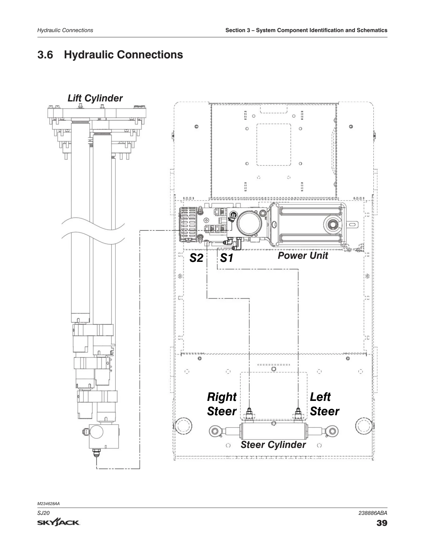
- Hydraulic connections
- Platform control box wiring and platform control cable wiring (including SGLE)
- Beeper, base limit switch, platform limit switches
- Motor and controller connections, mast cable
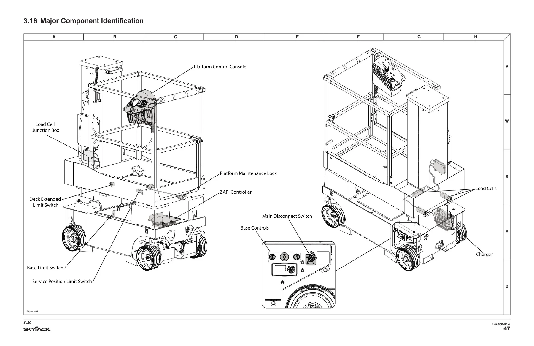
- Major component identification
- Hydraulic schematic, base control wiring
- Main harness ZAPI A and ZAPI B, electrical schematic
- Section 4 – Troubleshooting Information
- Electrical system: all controls inoperative, no lift or steer functions
- No lift or lower from base or platform, no functions from platform controls
- No steer left, no steer right, no drive
- Hydraulic system: all hydraulic controls inoperative, no lift function
- No lower function, no steer left and/or right
- Section 5 – Procedures
- Display module and display messages
- Wheel reinstallation and torquing procedure
- Battery maintenance, charger maintenance, charger profiles
- Charger troubleshooting and charger error codes
- Outer mast lubrication and inner mast lubrication
- Platform removal and platform installation
- Lift cylinder removal and lift cylinder installation
- Mast and lift cylinder removal and installation
- Wear pad replacement, mast identification, mast cable installation
- Railing maintenance and repair
What separates this manual from a parts list or an operator’s booklet is that the sections are wired together. The inspection checklist in Section 1 points at the procedures in Section 5. The troubleshooting tables in Section 4 send you to specific wire numbers and coil references – 3H-14 for the lift coil, 4H-23 and 4H-24 for the steer coils, 2H-13 for the lower coil – and those same numbers appear in the wiring diagrams in Section 3 and the hydraulic schematic in Section 3.17. Torque values appear twice by design: once as a quick table in Section 2.5 for the common base, mast and lift cylinder fasteners, and again as full imperial and metric tables covering everything from a 4-40 screw to a 1-1/2 inch bolt.
What You Can Do With This Manual
An SJ20 that is lifted on a mast with five sections of wear pads, a multistage lift cylinder and a Delta-Q charger has a predictable set of jobs that come up. This manual supports most of them:
- Run the frequent, periodic and annual inspection program and record it correctly on the owner’s annual inspection record
- Diagnose a machine that will not lift, will not lower, will not steer left or right, or will not drive, using the troubleshooting tables and the wire number / colour code reference
- Read and act on the display module messages, from M8-CTRL_ERR and M66-LOW_BATT through the load cell, tilt sensor, brake and charger fault codes
- Remove and refit the platform, the lower platform, the traverse platform and the front rollers
- Remove and install the lift cylinder, including the holding valve manifold, hex standoff and electrical connector
- Remove and install the complete mast assembly and rebuild it section by section
- Replace the top and bottom wear pads on masts 1 through 5 and reinstall the mast cable with the correct tape markers and weighted rollers
- Torque fasteners correctly – for example 203 Nm (150 ft-lb) on the front wheel castle nut and 68 Nm (50 ft-lb) to seat the rear wheel bearings
- Service the batteries, select the correct Delta-Q charger profile for the fitted battery, and clear charger fault and error codes
- Lubricate the outer and inner mast with the specified PTFE wax-based dry lubricant and the correct 38 mm strip pattern
Torque and Capacity Data in One Place
Section 2 pulls the numbers out of the procedures so you are not hunting through a reassembly step for a value. The hose numbering system is explained with a worked example – H1104 0081 2 decodes to a 37 degree JIC female swivel on one end, a medium 90 degree JIC female swivel on the other, SAE 100R13 specification and 81-1/2 inches overall. The fitting arrangement schedule that follows covers every hose prefix from H15 to H71 with both end fittings and the SAE hose specification for each. Floor loading pressure is given in both ANSI/CSA form and with the local concentrated pressure and overall floor load figures, so you can check whether a floor or a mezzanine will carry the machine before you drive onto it.
Why Correct Procedures Matter Here
This is a machine that lifts a person. The manual is direct about that throughout – lock and tag a MEWP that does not function correctly, keep personnel clear of unsupported components, disconnect the main power connectors before repair work, and never substitute tyres, batteries or railings with parts of different weight or dimensions because stability depends on them. The wear pad and mast sections in Section 5.13 are especially unforgiving: masts must come out one section at a time in the numbered order, and the caution notes about crush hazards and dry, unlubricated wear pads before lifting are there for a reason. Following the documented sequence is the difference between a lift that returns to service and one that comes back.
IMAGES PREVIEW
Instant PDF Delivery
The Skyjack SJ20 service manual is delivered as an instant PDF download after checkout – no shipping, no waiting on a parcel. Open it on a laptop, tablet or phone in the workshop, print the checklist pages and the torque tables you need for the job in front of you, and keep the schematics on screen while you trace a circuit. Everything is in one file: the schedules, the capacity and floor loading data, the symbol charts, the parts lists, the schematics and the step-by-step procedures.

Reviews
There are no reviews yet.