Trusted Business
Verified & Licensed
Virus Free Files
100% Safe Downloads
Secure Payment
SSL Protected
Instant Delivery
Available Immediately
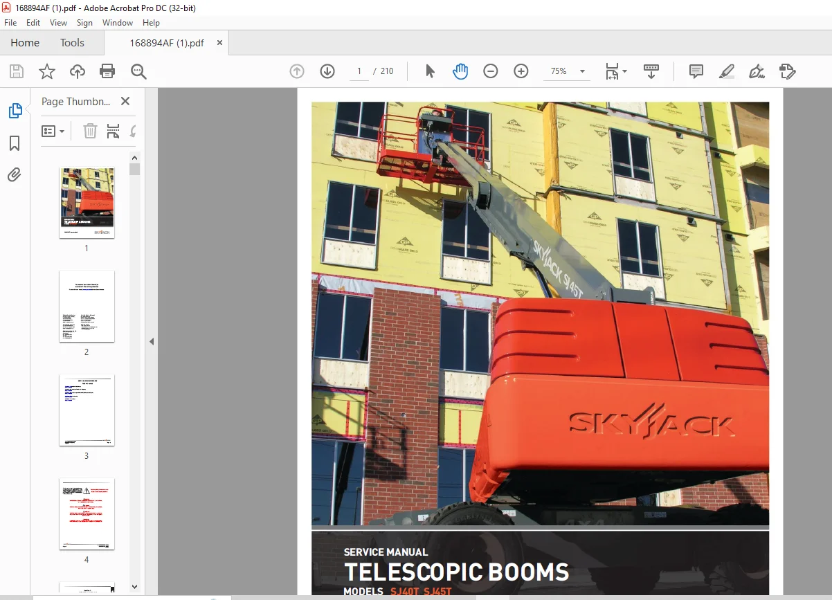
Skyjack SJ40T SJ45T Telescopic Boom Service Manual – PDF DOWNLOAD
$28.95
Skyjack SJ40T SJ45T Telescopic Boom Service Manual – PDF DOWNLOAD
SJ40T & SJ45T: 98001331 through 98001500
Instant PDF Download
Available immediately
Save to Your Device
Download & keep forever
Antivirus Scanned
100% virus-free
Trusted Worldwide
175,000+ customers
Description
Skyjack SJ40T SJ45T Telescopic Boom Service Manual – PDF DOWNLOAD
FILE DETAILS:
Skyjack SJ40T SJ45T Telescopic Boom Service Manual – PDF DOWNLOAD
Language : English
Pages : 210
Downloadable : Yes
File Type : PDF
IMAGES PREVIEW OF THE MANUAL:
DESCRIPTION:
Skyjack SJ40T SJ45T Telescopic Boom Service Manual – PDF DOWNLOAD
SJ40T & SJ45T: 98001331 through 98001500
SKYJACK is continuously improving and expanding product features on its equipment, therefore,
specifications and dimensions are subject to change without notice.
specifications and dimensions are subject to change without notice.
Aerial Platform Definition:
A mobile device that has an adjustable position platform supported from ground level by a
structure.
A mobile device that has an adjustable position platform supported from ground level by a
structure.
Purpose of Equipment:
The SKYJACK Telescopic Boom Series (Models SJ 40T, 45T, 61T & 66T) aerial platform is designed to
transport and raise personnel, tools and materials to overhead work areas
The SKYJACK Telescopic Boom Series (Models SJ 40T, 45T, 61T & 66T) aerial platform is designed to
transport and raise personnel, tools and materials to overhead work areas
Use of Equipment:
The aerial platform is a highly maneuverable, mobile work station. Lifting and driving must be on a
flat, level, compacted surface. It can be driven over uneven terrain only when the platform is
fully lowered.
The aerial platform is a highly maneuverable, mobile work station. Lifting and driving must be on a
flat, level, compacted surface. It can be driven over uneven terrain only when the platform is
fully lowered.
Manuals:
Operating:
The operating manual is considered a fundamental part of the aerial platform. It is a very
important way to communicate necessary safety information to users and operators. A complete and
legible copy of the operating manual must be kept in the provided weather-resistant storage
compartment on the aerial platform at all times.
Service & Maintenance:
- The purpose of this is to provide the customer with the servicing and maintenance procedures
essential for the promotion of proper machine operation for its intended purpose. - All information in this manual should be read and understood before any attempt is made to service
the machine.
Service Policy and Warranty:
SKYJACK warrants each new SJT series work platform to be free of defective parts and workmanship
for the first 24 months. Any defective part will be replaced or repaired by your local SKYJACK
dealer at no charge for parts or labor. Contact SKYJACK Service Department for warranty statement
extensions or exclusions.
Operator Safety Reminders, Warnings, and Precautions:
Operator safety is SKYJACK’s priority. The operator should comply with all applicable
safety-related reminders, warnings and precautions found in the Operating Manual. They should be
read and understood completely before operating the aerial platform.
Operator safety is SKYJACK’s priority. The operator should comply with all applicable
safety-related reminders, warnings and precautions found in the Operating Manual. They should be
read and understood completely before operating the aerial platform.
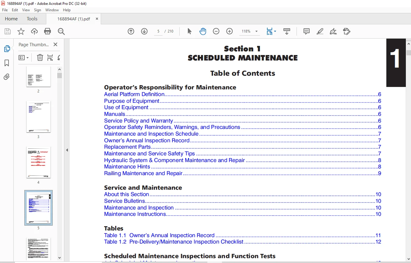
TABLE OF CONTENTS:
Skyjack SJ40T SJ45T Telescopic Boom Service Manual – PDF DOWNLOAD
Cover....................................................................................  1
Table of Contents........................................................................  3
Section 1 - Scheduled Maintenance........................................................  5
	Operator’s Responsibility for Maintenance............................................  6
		Aerial Platform Definition.......................................................  6
		Purpose of Equipment.............................................................  6
		Use of Equipment.................................................................  6
		Manuals..........................................................................  6
		Service Policy and Warranty......................................................  6
		Operator Safety Reminders, Warnings, and Precautions.............................  6
		Maintenance and Inspection Schedule..............................................  7
		Owner’s Annual Inspection Record.................................................  7
		Replacement Parts................................................................  7
		Maintenance and Service Safety Tips..............................................  7
		Hydraulic System & Component Maintenance and Repair..............................  8
		Maintenance Hints................................................................  8
		Railing Maintenance and Repair...................................................  9
	Service and Maintenance.............................................................. 10
		About this Section............................................................... 10
		Service Bulletins................................................................ 10
		Maintenance and Inspection....................................................... 10
		Maintenance Instructions......................................................... 10
	Tables............................................................................... 11
		Table 1.1  Owner’s Annual Inspection Record...................................... 11
		Table 1.2  Pre-Delivery/Maintenance Inspection Checklist......................... 12
	Scheduled Maintenance Inspections and Function Tests................................. 13
		1.1  Scheduled Maintenance Inspections........................................... 13
		1.2  Function Tests.............................................................. 24
Section 2 - Maintenance Tables and Diagrams.............................................. 25
	Tables............................................................................... 26
		Table 2.1  Standard Hose Numbering System........................................ 26
		Table 2.2  Aerial Platform Torque Specifications................................. 28
		Table 2.3  Axles Torque Specifications........................................... 29
		Table 2.4  Torque Specifications for Fasteners (Imperial)........................ 30
		Table 2.5  Torque Specifications for Fasteners (Metric).......................... 31
		Table 2.6  Torque Specifications for Hydraulic Couplings & Hoses................. 32
		Table 2.7  Axles Maintenance Intervals........................................... 33
		Table 2.8  Tire Specifications................................................... 34
		Table 2.9  Floor Loading Pressure................................................ 35
		Table 2.10  Hydraulic Specifications............................................. 36
		Table 2.11  Specifications and Features.......................................... 37
	Diagrams............................................................................. 39
		Diagram 2.1  Dimension and Reach Diagram - SJ 40T................................ 39
		Diagram 2.2  Dimension and Reach Diagram - SJ 45T................................ 40
		Diagram 2.3  Axle Oscillation Diagrams........................................... 41
Section 3 - System Component Identification and Schematics............................... 43
	Charts............................................................................... 45
		3.1  Hydraulic Symbol Chart...................................................... 45
		3.2  Electrical Symbol Chart..................................................... 46
		3.3  Wire Number and Color Code.................................................. 47
	Parts Lists.......................................................................... 48
		3.4  Hydraulic Schematic Parts List ............................................. 48
		3.5  Electrical Component Parts List............................................. 51
	Diagrams and Schematics.............................................................. 55
		3.6  Rotary Manifold and Port Identifications.................................... 55
		3.7  Brake Manifold and Port Identifications..................................... 56
		3.8  System Pump and Port Identifications........................................ 57
		3.9  Drive Pump and Port Identifications......................................... 58
		3.10  Drive Motor and Port Identifications....................................... 59
		3.11  Jib Valve and Port Identifications......................................... 60
		3.12  No Jib Valve and Port Identifications...................................... 61
		3.13  Pressure Reducing Manifold Port Identifications............................ 62
		3.14  Main Manifold and Port Identifications..................................... 63
		3.15  Main Manifold and Electrical Identifications............................... 64
		3.16  Main Manifold and Hydraulic Identifications................................ 65
		3.17  Main Harness Wiring Diagram................................................ 66
		3.18  ECU Engine Wiring Diagram (Deutz D2011 Diesel Engine)...................... 67
		3.19  Engine Interface Harness (Deutz D2.9L Diesel Engine)....................... 68
		3.20  Engine Interface Harness (GM Dual Fuel Engine)............................. 69
		3.21  Glow Plug Harness (Deutz D2.9L Diesel Engine).............................. 70
		3.22  Glow Plug Harness (Deutz D2011 Diesel Engine).............................. 71
		3.23  Harnesses.................................................................. 72
		3.24  Platform Control Cable Harnesses........................................... 73
		3.25  Limit Switch Connections................................................... 74
		3.26  Load Sensing Cable Connection (CE & AS).................................... 75
		3.27  Flashing Amber Light Connection............................................ 76
		3.28  Oil Cooler Harness Connections............................................. 77
		3.29  Generator Wire Kit Connections............................................. 78
		3.30  SGE Wiring Diagram......................................................... 79
		3.31  Telematics Wiring Diagram.................................................. 80
		3.32  Hydraulic Schematic Diagram................................................ 81
		3.33  Platform Control Console Diagram (40T ANSI/CSA - GM Dual Fuel Engine)...... 82
		3.34  Platform Control Console Diagram (40T ANSI/CSA - Deutz Diesel Engine)...... 83
		3.35  Platform Control Console Diagram (45T ANSI/CSA - GM Dual Fuel Engine)...... 84
		3.36  Platform Control Console Diagram (45T ANSI/CSA - Deutz Diesel Engine)...... 85
		3.37  Platform Control Console Diagram (45T CE - Deutz Diesel Engine)............ 86
		3.38  Platform Control Console Diagram (45T AS - Deutz Diesel Engine)............ 87
		3.39  Base Control Console Diagram (40T ANSI/CSA - GM Dual Fuel Engine).......... 88
		3.40  Base Control Console Diagram (40T ANSI/CSA - Deutz D2011 Diesel Engine).... 89
		3.41  Base Control Console Diagram (40T ANSI/CSA - Deutz D2.9L Diesel Engine).... 90
		3.42  Base Control Console Diagram (45T ANSI/CSA - GM Dual Fuel Engine).......... 91
		3.43  Base Control Console Diagram (45T ANSI/CSA - Deutz D2011 Diesel Engine).... 92
		3.44  Base Control Console Diagram (45T ANSI/CSA - Deutz D2.9L Diesel Engine).... 93
		3.45  Base Control Console Diagram (45T CE - Deutz D2011 Diesel Engine).......... 94
		3.46  Base Control Console Diagram (45T AS - Deutz D2011 Diesel Engine).......... 95
		3.47  Electrical Schematic Diagram  (ANSI/CSA - GM Dual Fuel Engine)............. 96
		3.48  Electrical Schematic Diagram (ANSI/CSA - Deutz D2011 Diesel Engine)........ 97
		3.49  Electrical Schematic Diagram (ANSI/CSA - Deutz D2.9L Diesel Engine)........ 98
		3.50  Electrical Schematic Diagram (CE - Deutz D2011 Diesel Engine).............. 99
		3.51  Electrical Schematic Diagram (AS - Deutz D2011 Diesel Engine)..............100
		3.52  Interface & Engine Electrical Schematic - GM Dual Fuel Engine  ............101
		3.53  Interface & Engine Electrical Schematic - Deutz D2.9L Diesel ..............102
		Introduction.....................................................................105
Section 4 - Troubleshooting Information..................................................103
	4.1  Electrical System...............................................................106
		4.1-1  All Controls Inoperative..................................................106
		4.1-2 No Power To Platform.......................................................106
		4.1-3 No Power to Base...........................................................107
		4.1-4 Engine Will Not Crank from Base ...........................................107
		4.1-5 Engine Will Not Crank from Platform........................................107
		4.1-6 Engine Will Not Crank from Platform or Base (Deutz Diesel D2.9L)...........108
		4.1-7 Engine Cranks but Will Not Start (Deutz Diesel D2.9L)......................108
		4.1-8 Engine Will Not Crank from Platform or Base (Deutz Diesel D2011)...........109
		4.1-9 Engine Cranks but Will Not Start (Deutz Diesel D2011)......................109
		4.1-10 Engine Will Not Crank from Platform or Base Control (GM Dual Fuel)........110
		4.1-11 Engine Cranks but Will Not Start (GM Dual Fuel)...........................111
		4.1-12 Glow Plug Circuit Inoperative (Deutz D2011 diesel engine).................113
		4.1-13 All Base Control Console Inoperative......................................113
		4.1-14 No Main Boom Down or Turret Rotate from Base Control Console..............114
		4.1-15 No Boom Up from Base Control Console......................................114
		4.1-16 No Boom Down from Base Control Console....................................114
		4.1-17 No Turret Rotate Left from Base Control Console...........................115
		4.1-18 No Turret Rotate Right from Base Control Console..........................115
		4.1-19 No Telescope Retract From Base Control Console............................115
		4.1-20 No Telescope Extend From Base Control Console.............................116
		4.1-21 No Platform Rotate Left From Base Control Console.........................116
		4.1-22 No Platform Rotate Right from Base Control Console........................117
		4.1-23 No Platform Rotate Left or Right from Base Control Console................117
		4.1-24 No Jib Up from Base Control Console.......................................117
		4.1-25 No Jib Down from Base Control Console.....................................118
		4.1-26 No Jib Up Or Down From Base Control Console...............................118
		4.1-27 No Manual Platform Level Up From Base Control Console.....................118
		4.1-28 No Manual Platform Level Down From Base Control Console...................119
		4.1-29 No Manual Platform Level Up From Platform Control Console.................119
		4.1-30 No Manual Platform Level Down From Platform Control Console...............120
		4.1-31 All Controls Inoperative From Platform Control Console....................120
		4.1-32 No Boom Up From Platform Control Console..................................121
		4.1-33 No Boom Down From Platform Control Console................................121
		4.1-34 No Turret Left from Platform Control Console..............................122
		4.1-35 No Turret Right from Platform Control Console.............................123
		4.1-36 No Telescope In from Platform Control Console.............................123
		4.1-37 No Telescope Out from Platform Control Console............................124
		4.1-38 No Platform Rotate or Jib Function from Platform Control Console..........125
		4.1-39 No Platform Rotate Left from Platform Control Console.....................125
		4.1-40 No Platform Rotate Right from Platform Control Console....................126
		4.1-41 No Jib Up from Platform Control Console...................................126
		4.1-42 No Jib Down from Platform Control Console.................................126
		4.1-43 Throttle Inoperative, Mid and High (Deutz D2.9L only).....................127
		4.1-44 Mid Throttle Inoperative..................................................127
		4.1-45 High Throttle Inoperative.................................................128
		4.1-46 Brake will not Release....................................................129
		4.1-47 No Drive and Steer........................................................129
		4.1-48 No Forward Drive..........................................................129
		4.1-49 No Reverse Drive..........................................................130
		4.1-50 No High Speed Drive.......................................................130
		4.1-51 No Elevated Drive.........................................................131
		4.1-52 No Left Steer.............................................................132
		4.1-53 No Right Steer............................................................132
		4.1-54 Direction Sensing Inoperative.............................................133
		4.1-55 Steer Direction Sensing Inoperative.......................................133
	4.2 Hydraulic System.................................................................134
		4.2-1 All Controls Inoperative...................................................134
		4.2-2 All Boom Functions Inoperative.............................................134
		4.2-3 No Main Boom Up............................................................134
		4.2-4 No Main Boom Down..........................................................134
		4.2-5 No Turret Rotate Left......................................................135
		4.2-6 No Turret Rotate Right.....................................................135
		4.2-7 No Boom Extend.............................................................136
		4.2-8 No Boom Retract............................................................136
		4.2-9 No Jib Up..................................................................136
		4.2-10 No Jib Down...............................................................137
		4.2-11 No Platform Rotation Right................................................137
		4.2-12 No Platform Rotation Left.................................................137
		4.2-13 Platform will not Level Down..............................................138
		4.2-14 Platform will not Level Up................................................138
		4.2-15 Brake will not Release....................................................138
		4.2-16 Brake will not Engage.....................................................139
		4.2-17 No Drive Forward or Reverse...............................................139
		4.2-18 No Forward Drive..........................................................139
		4.2-19 No Reverse Drive..........................................................139
		4.2-20 No High Speed Drive.......................................................140
		4.2-21 No Right Steer............................................................140
		4.2-22 No Left Steer.............................................................140
		4.2-23 Axle Will Not Oscillate...................................................140
		4.2-24 Axle Will Not Lock........................................................140
	4.3 Load Sensing System - CE.........................................................141
		4.3-1 Green Power LED is not Flashing............................................141
		4.3-2 Load Cell red Alarm LED is ON (with platform empty)........................141
		4.3-3 Red Error LED is ON........................................................141
		4.3-4 Load Cell red Alarm LED is OFF (with platform overloaded)..................141
		4.3-5 Platform Indicator Light does not turn ON..................................141
		4.3-6 Audible Alarm does not turn ON.............................................141
		4.3-7 Boom and Drive Functions are Enabled (with boom extended)..................141
		General..........................................................................145
		Safety and Workmanship...........................................................145
Section 5 - Procedures...................................................................143
	Platform.............................................................................145
		5.1-1  Human Machine Interface (HMI).............................................145
		5.1-2  User Interface Keys.......................................................146
			OCM Character Functions Charts...............................................146
			OCM Operating Values Chart...................................................147
		5.1-3  How to Select Functionality...............................................148
		5.1-4  How to View OCM Operation.................................................149
		5.1-5  How to Unlock and Modify OCM Settings.....................................150
		5.1-6  OCM Pin Voltage Reference.................................................151
		5.1-7  Fly Boom Switch Voltage References........................................154
		5.1-8  Platform Controller Voltage References....................................155
	Boom.................................................................................156
		5.2-1  Check Wear Pads...........................................................156
		5.2-2  Shimming Wear Pads........................................................156
		5.2-3  Cable Carrier Repair......................................................156
	Turret...............................................................................157
		5.3-1  High Pressure Filter Replacement..........................................157
		5.3-2  Check Swing Drive Motor Gearbox Oil.......................................157
		5.3-3  Turret Rotation Gear Backlash Adjustment..................................157
		5.3-4  Change Swing Drive Motor Oil..............................................158
		5.3-5  Battery Replacement.......................................................158
		5.3-6  Bolt Torque Procedure.....................................................159
			Rotary Actuator Bolt Torque Sequence.........................................159
			Turret Rotation Gear Bolt Torque Sequence....................................159
		5.3-7  Electronic Tilt Switch Setup Procedure....................................159
			Tilt Switch Replacement......................................................159
			Reprogramming Existing Tilt Switch...........................................161
			Test and Verify Tilt Circuit.................................................162
		5.3-8  Check Rotation Bearing for Axial Wear.....................................162
	Deutz Diesel Engine..................................................................163
		5.4-1  Replace Engine Oil and Filter.............................................163
		5.4-2  Replace Fuel Filter.......................................................164
		5.4-3  Replace Air Filter........................................................164
		5.4-4  Check Engine Belt.........................................................164
		5.4-5  Check Oil Cooler..........................................................164
		5.4-6  Deutz D2.9L Fault Codes...................................................165
	GM Dual Fuel Engine..................................................................185
		5.5-1  GM Map and IAT Sensor.....................................................185
		5.5-2  LPG Temperature Sensor....................................................186
		5.5-3  Throttle Actuator.........................................................187
		5.5-4  Engine Coolant Temperature Sensor.........................................188
		5.5-5  ECU Pin Reference Chart...................................................189
		5.5-6  Fuse Block Layout.........................................................190
	Hydraulic Tank.......................................................................191
		5.6-1  Change Hydraulic Tank Filter..............................................191
		5.6-2  Change Hydraulic Oil......................................................191
	Manifold and Hydraulic Pumps.........................................................192
		5.7-1  Hydraulic Brake Pressure Adjustment.......................................192
		5.7-2  Hydraulic Standby Pressure Adjustment.....................................193
		5.7-3  Hydraulic High Pressure Adjustment........................................194
		5.7-4  Hydraulic System Relief Valve Adjustment..................................195
		5.7-8  Test Charge Pump Pressure on Drive Pump...................................197
		5.7-9  Test Forward Drive Pressure on Drive Pump.................................198
		5.7-10  Test Reverse Drive Pressure on Drive Pump................................198
	Axles................................................................................199
		5.8-1  Change Oil in Rear Axle...................................................199
		5.8-2  Change Oil in Front Axle..................................................199
		5.8-3  Check Oil Level in Torque Hub.............................................199
		5.8-4  Check Oil Level in Axle Gearbox...........................................200
		5.8-5  Change Oil in Axle Gearbox................................................200
		5.8-6  Bleeding Oscillating Axle Cylinders.......................................200
		5.8-7  Pin Brake Adjustments.....................................................201
		5.8-8  Brake Inspection..........................................................202
	Grease Points........................................................................203
		5.9-1  Lubrication...............................................................203
		5.9-2  Grease Turret Rotation Bearing............................................203
		5.9-3  Grease Turret Rotation Gear...............................................203
		5.9-4  Grease Cylinder Brackets..................................................204
		5.9-5  Grease Drive Axle.........................................................205
		5.9-6  Grease Drive Shaft........................................................205
	Options..............................................................................206
		5.10-1  Load Sensing System - CE.................................................206
Contact us: [email protected]
PLEASE NOTE:
- This is the SAME manual used by the dealers to troubleshoot any faults in your vehicle. This can be yours in 2 minutes after the payment is made.
- Contact us at [email protected] should you have any queries before your purchase or that you need any other service / repair / parts operators manual.
S.V