
Skyjack SJ46 AJ+ SJ46 AJ SJ51 AJ Articulating Boom Service Manual 229042AFA (2024)
Original price was: $39.95.$24.95Current price is: $24.95.
Service and maintenance manual for Skyjack SJ46 AJ+, SJ46 AJ and SJ51 AJ articulating boom MEWPs. Document 229042AFA dated January 25 2024 covers scheduled maintenance, specifications, electrical and hydraulic schematics, troubleshooting, control systems, repair procedures, engine service information, load sensing, boom and axle procedures, and generator options.
Description
Skyjack SJ46 AJ+ SJ46 AJ SJ51 AJ Articulating Boom Service Manual 229042AFA (2024)
The Skyjack SJ46 AJ+ SJ46 AJ SJ51 AJ Articulating Boom Service Manual 229042AFA (2024) provides detailed servicing and maintenance information for three Skyjack articulating boom models. It covers the SJ46 AJ+, SJ46 AJ and SJ51 AJ, with model-specific information for ANSI/CSA, CE and AS configurations where the procedures, wiring or machine data differ. The manual combines scheduled maintenance information, machine specifications, hydraulic and electrical reference material, troubleshooting charts and repair procedures in one 292-page document.
File Details
- Manual type: Service Manual
- Equipment: Articulating Booms
- Brand: Skyjack
- Models: SJ46 AJ+, SJ46 AJ, SJ51 AJ
- Document number: 229042AFA
- Date: January 25 2024
- Standards/configurations shown: ANSI/CSA, CE, AS
- Language: English
- Pages: 292
- File format: PDF
Serial Number Coverage
The manual identifies the applicable MEWP serial-number ranges directly at the beginning of the document. For SJ46 AJ+, coverage is A301 000 001 – A301 999 999. For SJ46 AJ, coverage is B301 000 001 – B301 999 999, and the SJ51 AJ range is B301 000 001 – B301 999 999. Matching the machine model and serial range is important because the manual includes configuration-specific electrical, load-sensing and hydraulic information.
Maintenance, Specifications and Diagnostic Reference
This Skyjack SJ46 AJ+, SJ46 AJ and SJ51 AJ service manual is built around practical workshop use. Scheduled-maintenance material covers inspection intervals, pre-delivery and periodic inspection points, electrical and hydraulic checks, engine and control compartments, the base, platform, boom assembly and optional equipment. Dedicated service tables provide fastener torque data in US Imperial and metric sizes, hydraulic coupling and hose torque values, MEWP-specific and axle torque specifications, axle service intervals, platform capacities, tire information, floor-loading data, hydraulic specifications, approved hydraulic and gear oils, dimensions, speeds and engine specifications.
The electrical and hydraulic sections provide much more than general maintenance guidance. They include symbol charts, wire-number and colour references, hydraulic and electrical parts lists, component-port identification, harness drawings, load-sensing connections, CANbus connections, platform and base control-box wiring, generator wiring, hydraulic schematics and electrical schematics for the applicable configurations and engines. The troubleshooting section then connects these systems to real machine symptoms such as controls being inoperative, engine cranking and starting problems, boom and riser movement faults, turret rotation faults, telescope faults, platform leveling and rotation faults, jib problems, drive and steering faults, brake-release problems, load-sensing issues and hydraulic-function failures.
Chapters Covered
- Section 1 – Scheduled Maintenance
- Read and Heed
- Maintenance and Service
- Scheduled Maintenance
- Owner’s Annual Inspection Record
- Pre-Delivery/Maintenance Inspection Checklist
- Scheduled Maintenance Inspections
- Function Tests
- Section 2 – Maintenance Tables and Diagrams
- Standard Hose Numbering System
- Torque Specifications for Fasteners – US Imperial and Metric
- Torque Specifications for Hydraulic Couplings & Hoses
- MEWP and Axle Torque Specifications
- Axle Maintenance Intervals
- Maximum Platform Capacity and Tire Specifications
- Floor Loading Pressure
- Hydraulic Specifications
- Hydraulic & Gear Oils
- Specifications & Features – Dimensions & Speeds
- Engine Specifications
- Reach & Dimension Diagrams for SJ46 AJ+, SJ46 AJ and SJ51 AJ
- Axle Oscillation Diagram
- Section 3 – System Component Identification and Schematics
- Electrical and Hydraulic Symbol Charts
- Wire Number and Colour Chart
- Hydraulic and Electrical Parts Lists
- Brake, Rotary, Main and Generator Manifold Components and Ports
- Drive and System Pump Ports and Drive Motor Ports
- Jib Valve and Pressure Reducing Valve Ports
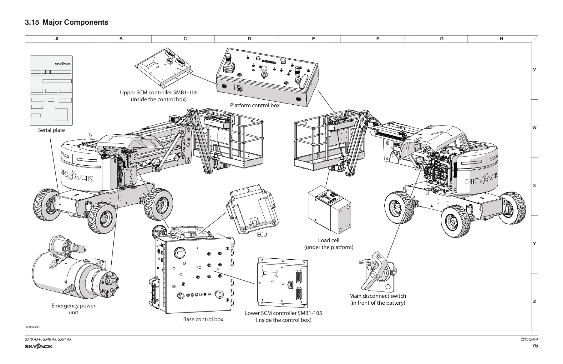
- Major Components
- Main, Engine Interface, Glow Plug and Platform Harnesses
- Limit Switch, Load Sensing, Motion Alarm, Footswitch, CANbus and Power Connections
- 3.5 kW and 12 kW Generator Wiring and Electrical Connections
- Load Circuit Wiring – SJ46 AJ+
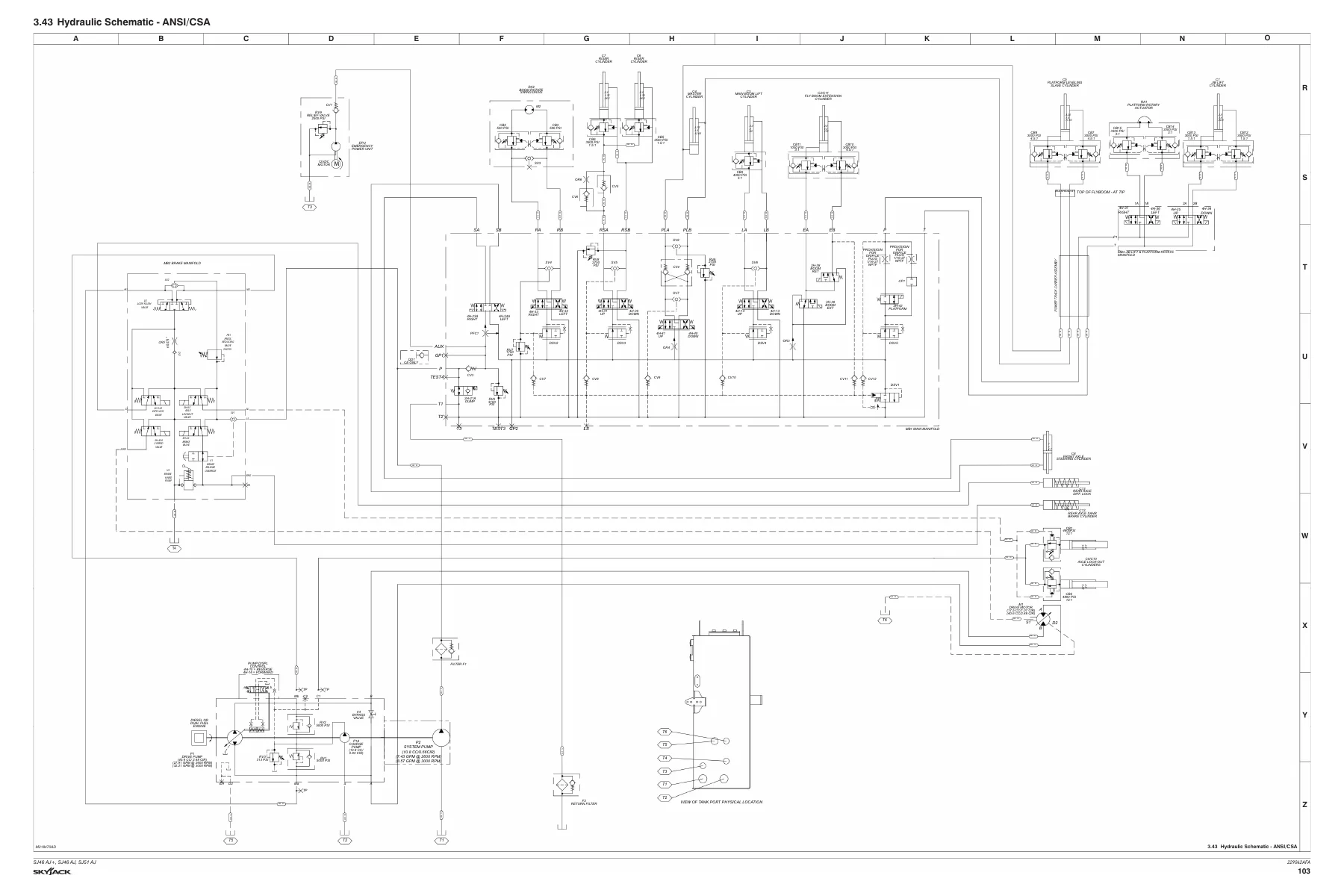
- Hydraulic Schematics – ANSI/CSA and CE & AS
- Platform Control Box Wiring – ANSI/CSA, CE and AS
- Base Control Box Wiring for applicable configurations
- Electrical and Engine Interface Schematics for Deutz and Kubota applications
- Section 4 – Troubleshooting Information
- Electrical System – ANSI/CSA
- Electrical System – CE & AS
- Load Sensing System – CE & AS
- Hydraulic System
- Section 5 – Procedures
- General safety and workmanship
- System Control Modules – OCM/SCM
- Platform voltage references and load-cell replacement
- Load Sensing System verification and calibration
- Boom wear pads, cable carrier, rotary actuator, cylinder and limit-switch procedures
- Turret filter, rotation gear, tilt switch and battery procedures
- Deutz Diesel Engine maintenance and fault-code information
- Hydraulic Oil and Filter Replacement
- Kubota WG2503 Dual Fuel Engine diagnostics and sensor references
- Manifold and Hydraulic Pump pressure tests and adjustments
- Axle, torque hub, gearbox, oscillating cylinder and brake procedures
- Grease Points
- Generator Troubleshooting and Frequency/Voltage Check & Adjustment
Together, these sections give a technician a structured path from routine inspection and service data through component identification, schematic tracing, symptom diagnosis and hands-on repair or adjustment. The document also separates ANSI/CSA, CE and AS information where needed, helping the reader follow the wiring, load-sensing and hydraulic information appropriate to the machine configuration.
Engine and Control-System Coverage
Engine-related reference material includes Deutz TD2.9L, Deutz D2.2, Deutz D2011 and Kubota WG2503 applications. The engine specification table provides RPM settings, output, fuel type, fuel-tank information, lubricant information and capacities where applicable. Procedure sections cover Deutz engine oil and filter service, fuel and air filters, belt checks, D2.9L fault-code retrieval and fault codes, while the Kubota WG2503 section includes KAntrak 1700 parameter display information, diagnostic trouble codes, ECU pin references, fuse-box information and sensor references.
The control-system procedures include OCM and SCM references, operating values, pin and voltage information, I/O checks, model selection, weight calibration and CAN Bus communication checks. Load-sensing procedures include operational verification and calibration, while platform and boom sections provide component-specific voltage references, wear-pad work, master-cylinder replacement and limit-switch locations. Hydraulic procedures cover brake pressure, relief-valve adjustments and drive-pump pressure testing, followed by axle lubrication, oscillating-cylinder, brake-inspection and grease-point procedures.
Service the SJ46 AJ+, SJ46 AJ and SJ51 AJ with the Correct Reference
The Skyjack SJ46 AJ+ SJ46 AJ SJ51 AJ Articulating Boom Service Manual 229042AFA (2024) supports maintenance inspections, electrical and hydraulic diagnosis, component checks, control-system work, pressure testing, adjustments, engine-related service, boom and platform repairs, axle work and generator troubleshooting using the procedures, diagrams and specifications provided for these machines. Having the correct model, serial-range and configuration information available helps technicians follow the intended procedures and use the specified torque values, pressures, capacities and electrical references during service. This manual is supplied as an instant PDF download after payment, with no physical shipping required. It can be viewed on compatible computers, tablets or phones and printed when a paper workshop reference is preferred.
Reviews
There are no reviews yet.