Skyjack SJ46AJ SJ51AJ Articulating Boom Lift Service Manual 194313AC – 2015 PDF Repair Guide
$39.95 Original price was: $39.95.$24.95Current price is: $24.95.
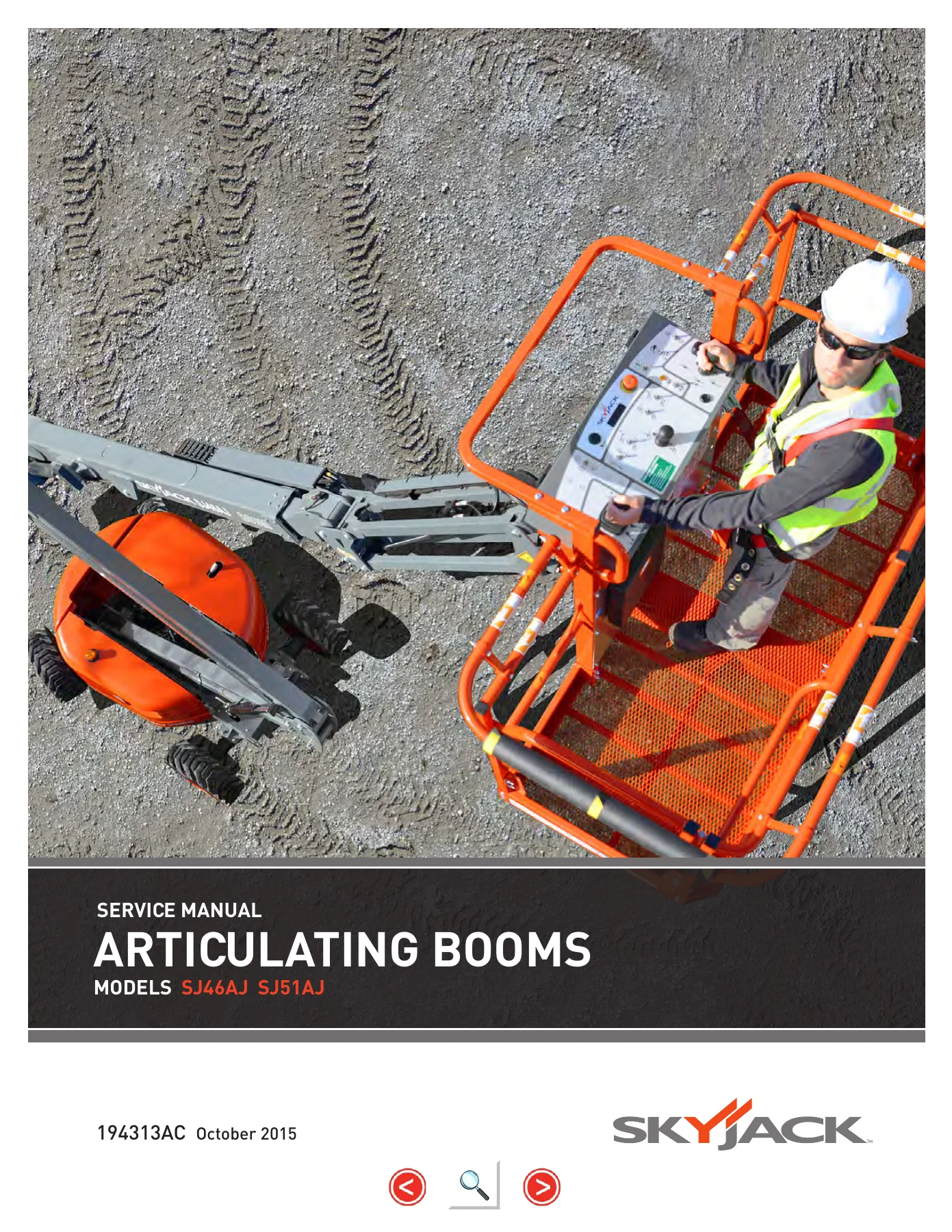
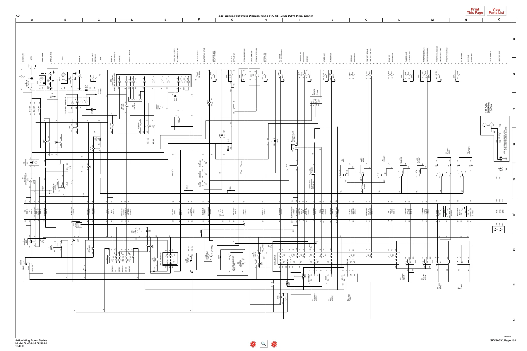
Complete Skyjack SJ46AJ and SJ51AJ articulating boom lift service manual, document 194313AC (October 2015). Covers scheduled maintenance, function tests, torque tables, hydraulic and electrical schematics, full troubleshooting, and step-by-step repair procedures. Instant PDF download.
Description
Skyjack SJ46AJ SJ51AJ Articulating Boom Lift Service Manual – Document 194313AC
This Skyjack SJ46AJ SJ51AJ Service Manual is the full service and maintenance reference for the SJ46AJ and SJ51AJ articulating boom lifts, published under document number 194313AC and dated October 2015. It covers machines from serial number 95 001 105 and above. Inside you will find scheduled maintenance inspections, function tests, maintenance tables, system component identification, complete hydraulic and electrical schematics, troubleshooting guides, and step-by-step service procedures.
The manual is structured so a technician can move from a symptom to a diagnosis to a repair without guessing. Whether you are servicing a Deutz diesel, a GM dual-fuel, or a Kubota dual-fuel engine variant, the wiring diagrams, hydraulic schematics, and component callouts are keyed to the correct serial range so the information matches the machine on the bench.
File Details
- Manual type: Service Manual
- Brand: Skyjack
- Models covered: SJ46AJ, SJ51AJ
- Document number: 194313AC
- Publication date: October 2015
- Serial number coverage: SJ46AJ & SJ51AJ: 95 001 105 and above
- Language: English
- File format: PDF
- Page count: Approximately 210 pages
Chapters and Sections Covered
-
Section 1 – Scheduled Maintenance
- Operator’s Responsibility for Maintenance
- Service and Maintenance
- Scheduled Maintenance Inspections
- Function Tests
- Owner’s Annual Inspection Record
- Pre-Delivery/Maintenance Inspection Checklist
Complete PDF Bookmark TreeComplete Bookmarks
The complete bookmarks in the βSkyjack SJ46AJ SJ51AJ Articulating Boom Lift Service Manual 194313AC – 2015 PDF Repair Guideβ are as follows:
Coverp. 1Table of Contentsp. 3+Section 1 – Scheduled Maintenancep. 5
+Operatorβs Responsibility for Maintenancep. 6
Aerial Platform Definitionp. 6Purpose of Equipmentp. 6Use of Equipmentp. 6Manualsp. 6Service Policy and Warrantyp. 6Operator Safety Reminders, Warnings, and Precautionsp. 6Maintenance and Inspection Schedulep. 7Ownerβs Annual Inspection Recordp. 7Replacement Partsp. 7Maintenance and Service Safety Tipsp. 7Hydraulic System & Component Maintenance and Repairp. 8Maintenance Hintsp. 8+Service and Maintenancep. 9
About this Sectionp. 9Service Bulletinsp. 9Maintenance and Inspectionp. 9Maintenance Instructionsp. 9+Tablesp. 10
Table 1.1 Ownerβs Annual Inspection Recordp. 10Table 1.2 Pre-Delivery/Maintenance Inspection Checklistp. 11+Scheduled Maintenance Inspections and Function Testsp. 12
1.1 Scheduled Maintenance Inspectionsp. 121.2 Function Testsp. 23+Section 2 – Maintenance Tables and Diagramsp. 25
+Tablesp. 26
Table 2.1 Standard Hose Numbering Systemp. 26Table 2.2 Aerial Platform Torque Specificationsp. 28Table 2.3 Axles Torque Specificationsp. 29Table 2.4 Torque Specifications for Fasteners (Imperial)p. 30Table 2.5 Torque Specifications for Fasteners (Metric)p. 31Table 2.6 Torque Specifications for Hydraulic Couplings & Hosesp. 32Table 2.7 Axles Maintenance Intervalsp. 33Table 2.8 Tire Specificationsp. 34Table 2.9 Maximum Platform Capacitiesp. 34Table 2.10 Floor Loading Pressurep. 35Table 2.11 Hydraulic Specificationsp. 36Table 2.12 Specifications and Featuresp. 37+Diagramsp. 39
Diagram 2.1 Dimension and Reach Diagram – SJ 46AJp. 39Diagram 2.2 Dimension and Reach Diagram – SJ 51AJp. 40Diagram 2.3 Axle Oscillation Diagramp. 41+Section 3 – System Component Identification and SChematicsp. 43
+Chartsp. 45
3.1 Hydraulic Symbol Chartp. 453.2 Electrical Symbol Chartp. 463.3 Wire Number and Color Codep. 47+Parts Listsp. 48
3.4 Hydraulic Component Parts Listp. 483.5 Electrical Component Parts Listp. 513.6 Brake Manifold and Port Identificationsp. 54+Diagrams and Schematicsp. 55
3.7 Rotary Manifold and Port Identificationsp. 553.8 Drive and System Pump and Port Identificationsp. 563.9 Drive and System Pump and Port Identifications (with Welder Option)p. 573.10 Drive Motors and Port Identificationsp. 583.11 Jib Valves and Port Identificationsp. 593.12 Pressure Reducing Valve Port Identificationsp. 603.13 Main Manifold and Port Identificationsp. 613.14 Generator Control Valve and Manifold Identificationp. 643.15 Main Electrical Harness and Fuel Level Switch Harnessp. 653.16 ECU Engine Wiring Diagram (Deutz D2011 Diesel Engine)p. 663.17 Glow Plug Harnesses (Deutz D2.9L Diesel Engine)p. 673.18 Glow Plug Harnesses (Deutz D2011 Diesel Engine)p. 683.19 Engine Interface Harness (GM Dual Fuel Engine)p. 693.20 Platform Harnessesp. 703.21 Platform Control Cable Harnessesp. 713.22 Limit Switch Connections at Base Control Consolep. 723.23 Load Sensing Cable Connection (CE & AS)p. 733.24 All Motion Alarm Connections (CE & AS)p. 743.25 Flashing Amber Light Optionp. 753.26 SGE Wiring Diagramp. 763.27 Oil Cooler and 3.5 kW Generator Base Control Console Wiringp. 773.28 Generator (3.5 kW) Platform Control Box Wiringp. 783.29 Oil Cooler and 12 kW Generator Base Control Console Wiringp. 793.30 Generator (12 kW) Platform Control Box Wiringp. 803.31 12kW Generator Connection Assemblyp. 813.32 Telematics Wiring Diagramp. 823.33 Load Circuit Wiringp. 833.33 Hydraulic Schematic Diagramp. 853.34 Platform Control Console Diagram (46AJ ANSI/CSA – GM Dual Fuel Engine)p. 863.35 Platform Control Console Diagram (46AJ ANSI/CSA – Deutz Diesel Engine)p. 873.36 Platform Control Console Diagram (46AJ & 51AJ CE – Deutz Diesel Engine)p. 883.37 Platform Control Console Diagram (46AJ & 51AJ AS – Deutz Diesel Engine)p. 893.38 Base Control Console Diagram (46AJ ANSI/CSA – GM Engine)p. 903.39 Base Control Console Diagram (46AJ ANSI/CSA – Kubota WG2503 Engine)p. 913.40 Base Control Console Diagram (46AJ ANSI/CSA – Deutz D2011 Diesel Engine)p. 923.41 Base Control Console Diagram (46AJ ANSI/CSA – Deutz D2011 Diesel Engine with Positive Air Shut-Off Option)p. 933.42 Base Control Console Diagram (46AJ & 51AJ CE – Deutz D2011 Diesel Engine)p. 943.43 Base Control Console Diagram (46AJ & 51AJ AS – Deutz D2011 Diesel Engine)p. 953.44 Base Control Console Diagram (46AJ ANSI/CSA – Deutz D2.9L Diesel Engine)p. 963.45 Electrical Schematic Diagram (46AJ ANSI/CSA – GM Dual Fuel Engine)p. 973.46 Electrical Schematic Diagram (46AJ ANSI/CSA – Kubota WG2503 Dual Fuel Engine)p. 983.47 Electrical Schematic Diagram (46AJ ANSI/CSA – Deutz D2011 Diesel Engine)p. 993.48 Electrical Schematic Diagram (46AJ ANSI/CSA – Deutz D2.9L Diesel Engine)p. 1003.49 Electrical Schematic Diagram (46AJ & 51AJ CE – Deutz D2011 Diesel Engine)p. 1013.50 Electrical Schematic Diagram (46AJ & 51AJ AS – Deutz D2011 Diesel Engine)p. 1023.51 Interface & Engine Electrical Schematic – GM Dual Fuel Enginep. 1033.52 Interface & Engine Electrical Schematic – Kubota WG2503 Dual Fuel Enginep. 1043.53 Interface & Engine Electrical Schematic – Deutz D2.9L Enginep. 1053.54 Engine Harness – Deutz D2.9Lp. 106+Section 4 – Troubleshooting Informationp. 107
Introductionp. 109+4.1 Electrical Systemp. 110
4.1-1 All Controls Inoperativep. 1104.1-2 No Power To Platformp. 1104.1-3 No Power to Basep. 1114.1-4 Engine Will Not Crank from Basep. 1114.1-5 Engine Will Not Crank from Platformp. 1114.1-6 Engine Will Not Crank from Platform or Base (Deutz Diesel D2.9Lp. 1124.1-7 Engine Cranks but Will Not Start (Deutz Diesel D2.9L)p. 1124.1-8 Engine Will Not Crank from Platform or Base (Deutz Diesel D2011)p. 1134.1-9 Engine Cranks but Will Not Start (Deutz Diesel D2011)p. 1134.1-10 Engine Will Not Crank from Platform or Base Control (GM Dual Fuel)p. 1144.1-11 Engine Cranks but Will Not Start (GM Dual Fuel)p. 1154.1-12 Glow Plug Circuit Inoperative (Deutz Diesel D2011 Engine)p. 1174.1-13 All Controls Inoperative from Base Consolep. 1174.1-14 No Main Boom Down, Riser Down or Turret Rotate from Base Control Consolep. 1184.1-15 No Boom Up from Base Control Consolep. 1184.1-16 No Boom Down from Base Control Consolep. 1184.1-17 No Riser Up from Base Control Consolep. 1194.1-18 No Riser Down from Base Control Consolep. 1194.1-19 No Turret Rotate Left from Base Control Consolep. 1194.1-20 No Turret Rotate Right from Base Control Consolep. 1204.1-21 No Telescope Retract from Base Control Consolep. 1204.1-22 No Telescope Extend from Base Control Consolep. 1204.1-23 No Platform Rotate Left from Base Control Consolep. 1214.1-24 No Platform Rotate Right from Base Control Consolep. 1214.1-25 No Jib Up from Base Control Consolep. 1224.1-26 No Jib Down from Base Control Consolep. 1224.1-27 No Manual Platform Level Up from Base Control Consolep. 1234.1-28 No Manual Platform Level Down from Base Control Consolep. 1234.1-29 All Controls Inoperative from Platform Control Consolep. 1244.1-30 No Boom Up from Platform Control Consolep. 1254.1-31 No Boom Down from Platform Control Consolep. 1254.1-32 No Riser Up from Platform Control Consolep. 1264.1-33 No Riser Down from Platform Control Consolep. 1264.1-34 No Turret Left from Platform Control Consolep. 1274.1-35 No Turret Right from Platform Control Consolep. 1284.1-36 No Toggle Switch Functions from Platform Control Consolep. 1284.1-37 No Telescope In from Platform Control Consolep. 1284.1-38 No Telescope Out from Platform Control Consolep. 1294.1-39 No Platform Rotate Left from Platform Control Consolep. 1294.1-40 No Platform Rotate Right from Platform Control Consolep. 1304.1-41 No Jib Up from Platform Control Consolep. 1314.1-42 No Jib Down from Platform Control Consolep. 1314.1-43 No Manual Platform Level Up from Platform Control Consolep. 1324.1-44 No Manual Platform Level Down from Platform Control Consolep. 1334.1-45 Throttle Inoperative, Mid and High (Deutz D2.9L only)p. 1334.1-46 Mid Throttle Inoperativep. 1344.1-47 High Throttle Inoperativep. 1354.1-48 Brake will not Releasep. 1354.1-49 Differential Lock will not Engagep. 1364.1-50 Differential Lock Engages Momentarily but will not stay Engagedp. 1364.1-51 No Drive and Steerp. 1374.1-52 No Forward Drivep. 1374.1-53 No Reverse Drivep. 1374.1-54 No High Speed Drivep. 1384.1-55 No Elevated Drivep. 1394.1-56 No Left Steerp. 1394.1-57 No Right Steerp. 1404.1-58 Direction Sensing Inoperativep. 140+4.2 Hydraulic Systemp. 141
4.2-1 All Controls Inoperativep. 1414.2-2 All Boom Functions Inoperativep. 1414.2-3 No Main Boom Upp. 1414.2-4 No Main Boom Downp. 1414.2-5 No Riser Boom Upp. 1424.2-6 No Riser Boom Downp. 1424.2-7 Riser Boom Down Jerkyp. 1424.2-8 No Turret Rotate Leftp. 1434.2-9 No Turret Rotate Rightp. 1434.2-10 No Boom Extendp. 1444.2-11 No Boom Retractp. 1444.2-12 No Jib Upp. 1444.2-13 No Jib Downp. 1444.2-14 No Platform Rotation Rightp. 1454.2-15 No Platform Rotation Leftp. 1454.2-16 Platform will not Level Down Manuallyp. 1454.2-17 Platform will not Level Up Manuallyp. 1464.2-18 Brake will not Releasep. 1464.2-19 Brake will not Engagep. 1474.2-20 Differential Lock will not Engagep. 1474.2-21 No Drive Forward or Reversep. 1474.2-22 No Forward Drivep. 1474.2-23 No Reverse Drivep. 1484.2-24 No High Speed Drivep. 1484.2-25 No Right Steerp. 1484.2-26 No Left Steerp. 1484.2-27 Axle Will Not Oscillatep. 1484.2-28 Axle Will Not Lockp. 149+4.3 Load Sensing System – CEp. 150
4.3-1 Green Power LED is not Flashingp. 1504.3-2 Load Cell red Alarm LED is ON (with platform empty)p. 1504.3-3 Red Error LED is ONp. 1504.3-4 Load Cell red Alarm LED is OFF (with platform overloaded)p. 1504.3-5 Platform Indicator Light does not turn ONp. 1504.3-6 Audible Alarm does not turn ONp. 1504.3-7 Boom and Drive Functions are Enabled (with boom extended)p. 150+Section 5 – Proceduresp. 151
Generalp. 153Safety and Workmanshipp. 153+Platformp. 153
5.1-1 Human Machine Interface (HMI)p. 1535.1-2 User Interface Keysp. 1545.1-3 How to Select Functionalityp. 1565.1-4 How to View OCM Operationp. 1575.1-5 How to Unlock and Modify OCM Settingsp. 1585.1-6 OCM Pin Voltage Referencep. 1595.1-7 Platform Controller Voltage Referencesp. 162+Boomp. 164
5.2-1 Check Wear Padsp. 1645.2-2 Shimming Wear Padsp. 1645.2-3 Cable Carrier Repairp. 1645.2-4 Master Cylinder Replacementp. 164+Turretp. 166
5.3-1 High Pressure Filter Replacementp. 1665.3-2 Check Swing Drive Motor Gearbox Oilp. 1665.3-3 Turret Rotation Gear Backlash Adjustmentp. 1665.3-4 Swing Drive Motor Removalp. 1675.3-5 Swing Drive Motor Replacementp. 1685.3-6 Swing Drive Brake and Gearbox Oil Replacementp. 1685.3-7 Battery Replacementp. 1685.3-8 Bolt Torque Procedurep. 1695.3-9 Electronic Tilt Switch Setup Procedurep. 1705.3-10 Check Rotation Bearing for Axial Wearp. 173+Deutz Diesel Enginep. 174
5.4-1 Engine Oil and Filter Replacementp. 1745.4-2 Fuel Filter Replacementp. 1755.4-3 Air Filter Replacementp. 1755.4-4 Check Engine Beltp. 1755.4-5 Check Oil Coolerp. 175+GM Dual Fuel Enginep. 176
5.5-1 GM Map and IAT Sensor (3.0L GM Engine)p. 1765.5-2 LPG Temperature Sensor (3.0L GM Engine)p. 1775.5-3 Throttle Actuator (3.0L GM Engine)p. 1785.5-4 Engine Coolant Temperature Sensor (3.0L GM Engine)p. 1795.5-5 ECU Pin Reference Chart (3.0L GM Engine)p. 1805.5-6 Fuse Block Layout (3.0L GM Engine)p. 181+Kubota WG2503 Dual Fuel Enginep. 182
5.6-1 Engine Parameter Display (KAntrak 1700)p. 1825.6-2 Diagnostic Trouble Codesp. 1835.6-3 ECU Pin Reference Chart (Kubota WG2503)p. 1885.6-4 Fuse Box (Kubota WG2503)p. 1895.6-5 MAP Sensor (Kubota WG2503)p. 1905.6-6 IAT Sensor (Kubota WG2503)p. 1905.6-7 ECT (Kubota WG2503)p. 1915.6-8 TPS & Engine Speed (Kubota WG2503)p. 1915.6-9 Fuel Temperature Sensor (Kubota WG2503)p. 1925.6-10 Oil Pressure Sensor (Kubota WG2503)p. 192+Hydraulic Tankp. 193
5.7-1 Hydraulic Oil Replacementp. 1935.7-2 Hydraulic In-tank Filter Replacementp. 193+Manifold and Hydraulic Pumpsp. 194
5.8-1 Hydraulic Brake Pressure Adjustmentp. 1945.8-2 Hydraulic System Relief Valve Adjustmentp. 1955.8-3 Riser Down Relief Valve Adjustmentp. 1955.8-4 Turret Rotate Relief Valve Adjustmentp. 1965.8-5 Platform Level Relief Valve Adjustmentp. 1965.8-6 Test Charge Pump Pressure on Drive Pumpp. 1975.8-7 Test Forward Drive Pressure on Drive Pumpp. 1975.8-8 Test Reverse Drive Pressure on Drive Pumpp. 198+Axlesp. 198
5.9-1 Rear Axle Oil Replacementp. 1985.9-2 Front Axle Oil Replacementp. 1985.9-3 Check Torque Hub Oil Levelp. 1995.9-4 Check Axle Gearbox Oil Levelp. 1995.9-5 Axle Gearbox Oil Replacementp. 1995.9-6 Oscillating Cylinder Bolt Replacementp. 2005.9-7 Oscillating Cylinder Replacementp. 2005.9-8 Bleeding Oscillating Axle Cylindersp. 2025.9-9 Pin Brake Adjustmentsp. 202+Grease Pointsp. 204
5.10-1 Lubricationp. 204+Optionsp. 206
5.11-1 Load Sensing System – CEp. 206 -
Section 2 – Maintenance Tables and Diagrams
- Standard Hose Numbering System
- Aerial Platform Torque Specifications
- Axles Torque Specifications
- Torque Specifications for Fasteners (Imperial and Metric)
- Torque Specifications for Hydraulic Couplings and Hoses
- Axles Maintenance Intervals
- Tire Specifications
- Maximum Platform Capacities
- Floor Loading Pressure
- Hydraulic Specifications
- Specifications and Features
- Dimension and Reach Diagrams for SJ46AJ and SJ51AJ
- Axle Oscillation Diagram
-
Section 3 – System Component Identification and Schematics
- Hydraulic and Electrical Symbol Charts
- Wire Number and Color Code
- Hydraulic and Electrical Component Parts Lists
- Brake Manifold, Rotary Manifold, and Main Manifold Port Identifications
- Drive and System Pump Port Identifications
- Drive Motor and Jib Valve Port Identifications
- Pressure Reducing Valve Port Identifications
- Generator Control Valve and Manifold Identification
- Main Electrical Harness and Fuel Level Switch Harness
- ECU Engine Wiring Diagrams (Deutz D2011, Deutz D2.9L, GM Dual Fuel, Kubota WG2503)
- Glow Plug Harnesses
- Engine Interface Harness
- Platform Harnesses and Platform Control Cable Harnesses
- Limit Switch Connections
- Load Sensing Cable Connection (CE & AS)
- All Motion Alarm, Flashing Amber Light, SGE Wiring, Oil Cooler, Generator, Telematics, and Load Circuit Wiring
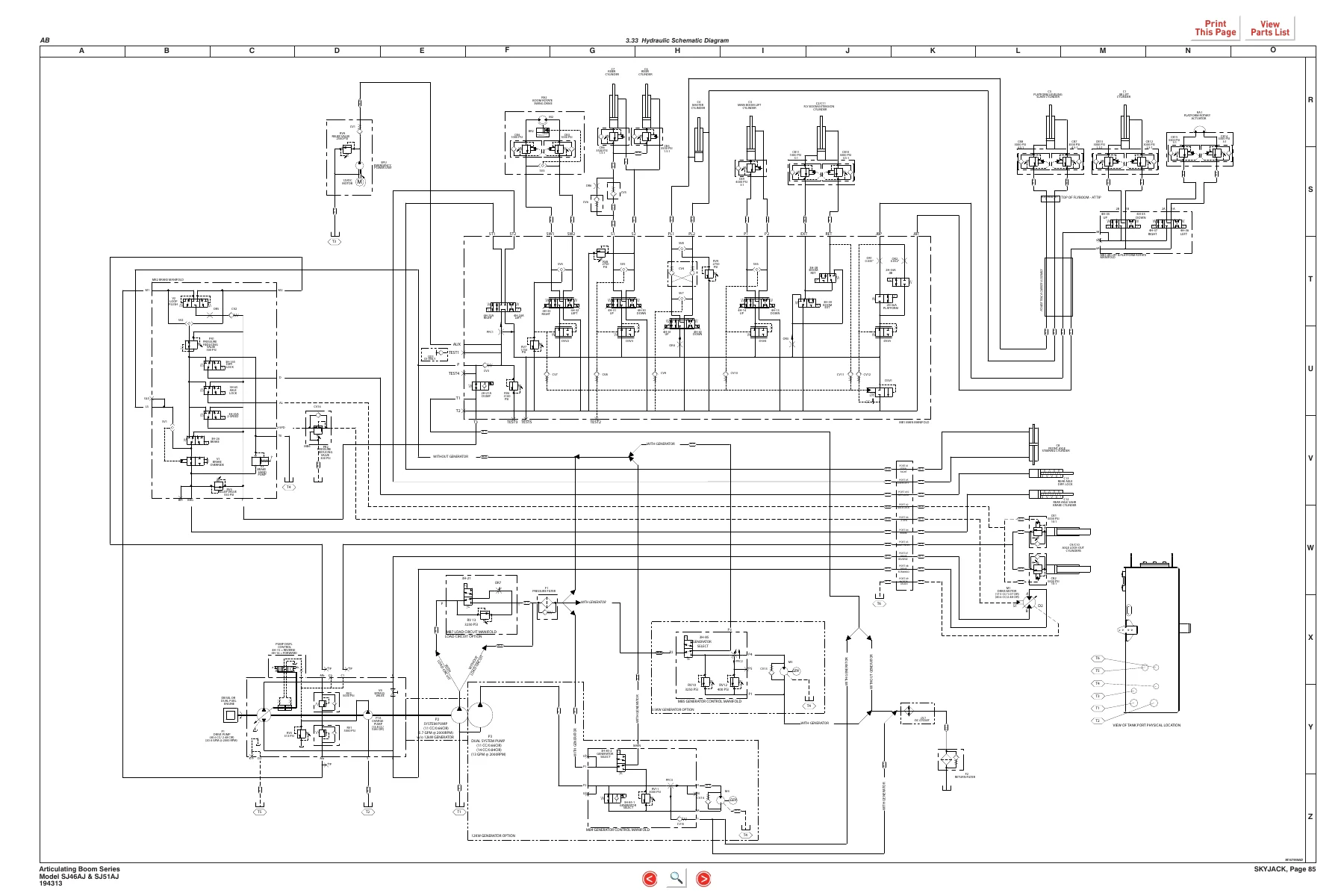
- Hydraulic Schematic Diagram
- Platform and Base Control Console Diagrams
- Electrical Schematic Diagrams
-
Section 4 – Troubleshooting
- Electrical System troubleshooting (engine crank, throttle, brake, drive, steer, functions from base and platform)
- Hydraulic System troubleshooting (boom, riser, turret, jib, platform, axle, brake, drive)
- Load Sensing System troubleshooting (CE)
-
Section 5 – Procedures
- Human Machine Interface (HMI) and OCM setup
- Boom – wear pads, cable carrier, master cylinder
- Turret – high pressure filter, swing drive, rotation gear backlash, battery, bolt torque, tilt switch, rotation bearing
- Deutz Diesel Engine procedures
- GM Dual Fuel Engine procedures
- Kubota WG2503 Dual Fuel Engine procedures
- Hydraulic Tank and oil replacement
- Manifold and Hydraulic Pump procedures
- Axles service procedures
- Grease points
- Load Sensing System calibration
Across its five sections, this Skyjack SJ46AJ SJ51AJ service manual gives a technician the full working picture of the machine: what to inspect and at what interval, how to test every function, how to identify each component and port, what to do when a fault appears, and how to replace or adjust the parts involved. The hydraulic and electrical schematics alone make it a valuable reference for diagnosing faults that a generic guide cannot resolve.
Engine and Powertrain Coverage
This manual is written to cover multiple engine configurations used across the SJ46AJ and SJ51AJ range, including the Deutz D2.9L diesel, Deutz D2011 diesel, GM 3.0L dual fuel, and Kubota WG2503 dual fuel engines. Engine-specific wiring diagrams, harnesses, fuse layouts, sensor references, and diagnostic trouble codes are included for each supported engine so the correct procedures match your machine.
IMAGES PREVIEW
Who This Manual Is For
This is a working document for service technicians, maintenance crews, and equipment owners responsible for the upkeep of SJ46AJ and SJ51AJ articulating boom lifts. The content assumes some familiarity with aerial platform systems, but the step-by-step procedures and troubleshooting flow charts make it usable by anyone who needs reliable, model-specific information rather than generic advice.
What You Can Do With This Manual
- Perform scheduled maintenance inspections at the correct intervals with the correct checklist
- Run complete function tests to verify boom, drive, steer, and platform operation before putting the machine back into service
- Diagnose electrical faults from the battery through the base console, boom cables, platform console, and every valve coil
- Diagnose hydraulic faults on the boom, riser, turret rotation, jib, platform leveling, steering, brake, and axle circuits
- Identify hydraulic and electrical components by port, wire number, and part number
- Remove and replace major components including swing drive motor, master cylinder, high pressure filter, batteries, and axle components
- Adjust relief valves, brake pressure, turret rotation gear backlash, and platform leveling circuits to specification
- Set up and calibrate the electronic tilt switch and load sensing system
- Reference torque values, tire specifications, capacities, and hydraulic pressures during any repair
Why the Right Manual Matters
Articulating boom lifts are complex machines with high-pressure hydraulics, multiple control systems, and strict stability requirements. Working from guesswork can damage components, compromise stability, or create an unsafe operating condition. This manual gives the exact torque values, pressures, clearances, and procedures that apply to the SJ46AJ and SJ51AJ, so every repair is done correctly the first time.
Instant PDF Delivery
The Skyjack SJ46AJ SJ51AJ Service Manual is delivered as a PDF download immediately after payment. There is no physical shipment, no waiting, and no shipping cost. The file can be viewed on any device that reads PDFs – computer, tablet, or smartphone – and can be printed for use in the shop. Keep it on hand for every service job, from a routine inspection to a full component replacement.
What Our Customers Say
π Related Products
Discover more professional manuals for your equipment

Case IH A8000 A8800 Cane Harvester Service Manual - Complete Workshop Repair Guide PDF

BOMAG BW27 RH-4i Rubber Tire Roller Service Manual 00892289 - PDF Download

Kubota 05 Series Diesel Engine Workshop Manual 1996 - D905 D1005 D1105 V1205 V1305 V1505 Service & Repair


Reviews
There are no reviews yet.