Skyjack SJ61T SJ66T Telescopic Booms Service Manual 143871AJ – PDF DOWNLOAD
$24.95
Skyjack SJ61T SJ66T Telescopic Booms Service Manual 143871AJ – PDF DOWNLOAD
Serial Number(s):
SJ61T & SJ66T 97 000 001 to 97 000 917
Description
Skyjack SJ61T SJ66T Telescopic Booms Service Manual 143871AJ – PDF DOWNLOAD
FILE DETAILS:
Skyjack SJ61T SJ66T Telescopic Booms Service Manual 143871AJ – PDF DOWNLOAD
Language : English
Pages :198
Downloadable : Yes
File Type : PDF
DESCRIPTION:
Skyjack SJ61T SJ66T Telescopic Booms Service Manual 143871AJ – PDF DOWNLOAD
Serial Number(s):
SJ61T & SJ66T 97 000 001 to 97 000 917
and dimensions are subject to change without notice.
Aerial Platform Definition
A mobile device that has an adjustable position platform supported from ground level by a structure.
Purpose of Equipment
The SKYJACK Telescopic Boom Series (Models SJ 40T, 45T, 61T & 66T) aerial platform is designed to transport
and raise personnel, tools and materials to overhead work areas
Use of Equipment
The aerial platform is a highly maneuverable, mobile work station. Lifting and driving must be on a flat, level,
compacted surface. It can be driven over uneven terrain only when the platform is fully lowered.
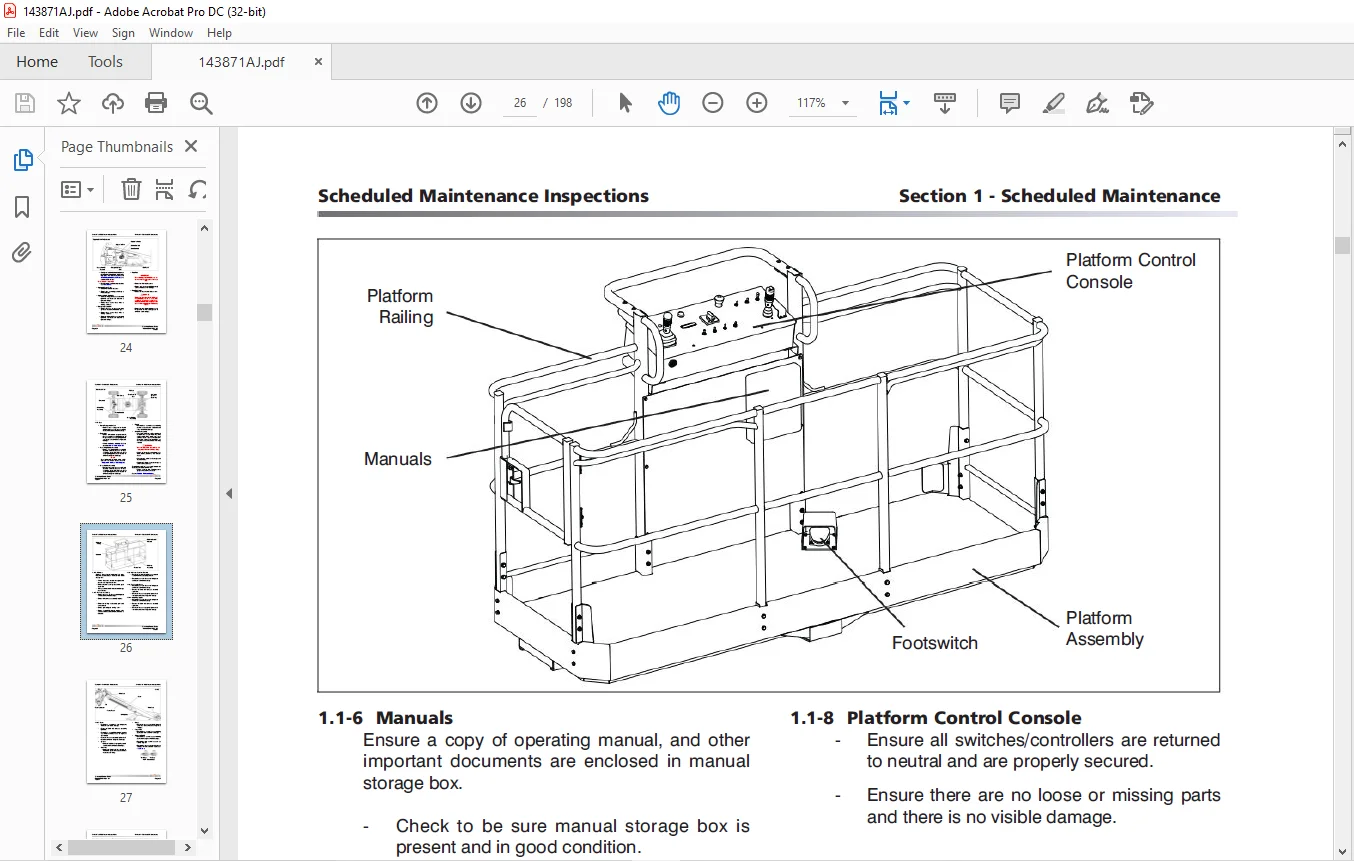
Manuals
Operating Manuals
The operating manual is considered a fundamental part of the aerial platform. It is a very important way to
communicate necessary safety information to users and operators. A complete and legible copy of this manual
must be kept in the provided weather-resistant storage compartment on the aerial platform at all times.
Service & Maintenance Manuals
The purpose of this is to provide the customer with the servicing and maintenance procedures essential for
the promotion of proper machine operation for its intended purpose.
All information in this manual should be read and understood before any attempt is made to service the machine.
The updated copy of the manuals are found on the company’s
IMAGES PREVIEW OF THE MANUAL:
TABLE OF CONTENTS:
Skyjack SJ61T SJ66T Telescopic Booms Service Manual 143871AJ – PDF DOWNLOAD
Cover 1
Table of Contents 3
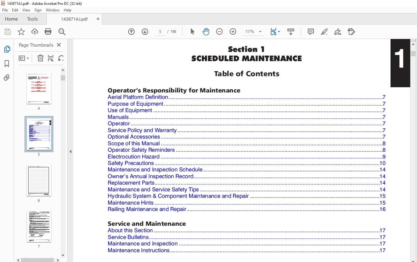
Section 1 – Scheduled Maintenance 5
Operator’s Responsibility for Maintenance 7
Aerial Platform Definition 7
Railing Maintenance and Repair 16
Maintenance Hints 15
Hydraulic System & Component Maintenance and Repair 15
Maintenance and Service Safety Tips 14
Replacement Parts 14
Owner’s Annual Inspection Record 14
Maintenance and Inspection Schedule 14
Safety Precautions 10
Electrocution Hazard 9
Operator Safety Reminders 8
Scope of this Manual 8
Purpose of Equipment 7
Use of Equipment 7
Manuals 7
Operator 7
Service Policy and Warranty 7
Optional Accessories 7
Service and Maintenance 17
About this Section 17
Service Bulletins 17
Maintenance and Inspection 17
Maintenance Instructions 17
Tables 18
Table 1 1 Owner’s Annual Inspection Record 18
Table 1 2 Maintenance and Inspection Checklist 19
Scheduled Maintenance Inspections and Function Tests 20
1 1 Scheduled Maintenance Inspections 20
1 2 Function Tests 29
Section 2 – Maintenance Tables and Diagrams 39
Tables 40
Table 2 1 Standard Hose Numbering System 40
Table 2 2 Aerial Platform Torque Specifications 42
Table 2 3 Axles Torque Specifications 43
Table 2 4 Axles Maintenance Intervals 44
Table 2 5 Tire Specifications 45
Table 2 6 Floor Loading Pressure 46
Table 2 7 Hydraulic Specifications 47
Table 2 8 Specifications and Features 48
Diagrams 50
Diagram 2 1 Dimension and Reach Diagram – SJ 61T 50
Diagram 2 2 Dimension and Reach Diagram – SJ 66T 51
Diagram 2 3 Axle Oscillation Diagrams 52
Section 3 – System Component Identification and Schematics 53
Charts 55
3 1 Hydraulic Symbol Chart 55
3 2 Electrical Symbol Chart 56
3 3 Wire Number and Color Code 57
Parts Lists 58
3 4 Hydraulic Schematic Parts List 58
3 5 Electrical Component Parts List 61
Diagrams and Schematics 64
3 6 Rotary Manifold and Port Identifications (Dual Mount Plates) 64
3 7 Brake Manifold and Port Identifications 65
3 8 System Pump and Port Identifications 66
3 9 Drive Pump and Port Identifications 67
3 10 Drive Motors and Port Identifications 68
3 11 Jib Valve and Port Identifications 69
3 12 No Jib Valve and Port Identifications 70
3 13a Main Manifold and Port Identifications 71
3 13b Main Manifold and Electrical Identifications 72
3 13c Main Manifold and Hydraulic Identifications 73
3 14 Main Harness Wiring Diagram 74
3 15 ECU Engine Wiring Diagram (Deutz Diesel Engine) 75
3 16 Glow Plug and EGR Harnesses (Deutz Diesel Engine) 76
3 17 Engine Interface Harness (GM Dual Fuel Engine) 77
3 18 Harnesses 78
3 19 Platform Control Cable Harnesses 79
3 20 Limit Switch Connections 80
3 21 Load Sensing Cable Connection (CE) 81
3 22a Hydraulic Schematic Diagram 83
3 22b Hydraulic Schematic Diagram 84
3 23 Platform Control Console Diagram (ANSI/CSA SJ 66T – Deutz Diesel Engine) 85
3 24 Platform Control Console Diagram (ANSI/CSA SJ 61T – Deutz Diesel Engine) 86
3 25 Platform Control Console Diagram (CE & AS SJ 66T – Deutz Diesel Engine) 87
3 26 Platform Control Console Diagram (ANSI/CSA SJ 66T – GM Dual Fuel Engine) 88
3 27 Platform Control Console Diagram (ANSI/CSA SJ 61T – GM Dual Fuel Engine) 89
3 28 Base Control Console Diagram (ANSI/CSA SJ 66T – Deutz Diesel Engine) 90
3 29 Base Control Console Diagram (ANSI/CSA SJ 61T – Deutz Diesel Engine) 91
3 30 Base Control Console Diagram (CE SJ 66T – Deutz Diesel Engine) 92
3 31 Base Control Console Diagram (AS SJ 66T – Deutz Diesel Engine) 93
3 32a Base Control Console Diagram (ANSI/CSA SJ 66T – GM Dual Fuel Tier 3 Engine) 94
3 32b Base Control Console Diagram (ANSI/CSA SJ 66T – GM Dual Fuel Tier 2 Engine) 95
3 33a Base Control Console Diagram (ANSI/CSA SJ 61T – GM Tier 3 Dual Fuel Engine) 96
3 33b Base Control Console Diagram (ANSI/CSA SJ 61T – GM Tier 2 Dual Fuel Engine) 97
3 34 Electrical Schematic Diagram (ANSI/CSA – Deutz Diesel Engine) 98
3 35 Electrical Schematic Diagram (ANSI/CSA – Deutz Diesel Engine with Generator Convenience) 99
3 36 Electrical Schematic Diagram (CE SJ 66T – Deutz Diesel Engine) 100
3 37 Electrical Schematic Diagram (AS SJ 66T – Deutz Diesel Engine) 101
3 38a Electrical Schematic Diagram (ANSI/CSA – GM Dual Fuel Tier 3 Engine) 102
3 38b Electrical Schematic Diagram (ANSI/CSA – GM Dual Fuel Tier 2 Engine) 103
3 39 Interface & Engine Electrical Schematic – GM Dual Fuel 104
3 41 Generator Control Valves and Port Indentifcations 105
3 42 Generator and Oil Cooler Harness Connections 106
3 43 Generator Wire Kit Connections 107
3 44 12kW Generator Connection Assembly 108
Introduction 111
Section 4 – Troubleshooting Information 109
4 1 Electrical System 112
4 1-1 All Controls Inoperative 112
4 1-2 No Power To Platform 112
4 1-3 No Power to Base 112
4 1-4 Engine Will Not Crank from Base 113
4 1-5 Engine Will Not Crank from Platform 113
4 1-6 Engine Will Not Crank from Platform or Base (Deutz Diesel) 114
4 1-7 Engine Cranks but Will Not Start (Deutz Diesel) 114
4 1-8 Engine Will Not Crank from Platform or Base Control (GM Dual Fuel) 115
4 1-9 Engine Cranks but Will Not Start (GM Dual Fuel) 115
4 1-10 Glow Plug Circuit Inoperative 118
4 1-11 All Controls Inoperative from Base Console 118
4 1-12 No Main Boom Down or Turret Rotate from Base Control Console 119
4 1-13 No Boom Up from Base Control Console 119
4 1-14 No Boom Down from Base Control Console 119
4 1-15 No Turret Rotate Left from Base Control Console 119
4 1-16 No Turret Rotate Right from Base Control Console 120
4 1-17 No Telescope Retract From Base Control Console 120
4 1-18 No Telescope Extend From Base Control Console 120
4 1-19 No Platform Rotate Left From Base Control Console 121
4 1-20 No Platform Rotate Right from Base Control Console 121
4 1-21 No Platform Rotate Left or Right from Base Control Console 122
4 1-22 No Jib Up from Base Control Console 122
4 1-23 No Jib Down from Base Control Console 123
4 1-24 No Jib Up Or Down From Base Control Console 123
4 1-25 No Manual Platform Level Up From Base Control Console 123
4 1-26 No Manual Platform Level Down From Base Control Console 124
4 1-27 No Manual Platform Level Up From Platform Control Console 124
4 1-28 No Manual Platform Level Down From Platform Control Console 125
4 1-29 All Controls Inoperative From Platform Control Console 126
4 1-30 No Boom Up From Platform Control Console 127
4 1-31 No Boom Down From Platform Control Console 127
4 1-32 No Turret Left from Platform Control Console 128
4 1-33 No Turret Right from Platform Control Console 128
4 1-34 No Toggle Switch Functions from Platform Control Console 129
4 1-35 No Telescope Out from Platform Control Console 129
4 1-36 No Telescope Out from Platform Control Console 130
4 1-37 No Platform Rotate or Jib Function from Platform Control Console 131
4 1-38 No Platform Rotate Left from Platform Control Console 131
4 1-39 No Platform Rotate Right from Platform Control Console 131
4 1-40 No Jib Up from Platform Control Console 132
4 1-41 No Jib Down from Platform Control Console 132
4 1-42 Mid Throttle Inoperative 132
4 1-43 High Throttle Inoperative 133
4 1-44 Brake will not Release 134
4 1-45 No Drive and Steer 134
4 1-46 No Forward Drive 135
4 1-47 No Reverse Drive 135
4 1-48 No High Speed Drive 136
4 1-49 No Elevated Drive 137
4 1-50 No Left Steer 137
4 1-51 No Right Steer 137
4 1-52 Direction Sensing Inoperative 138
4 1-53 Steer Direction Sensing Inoperative 138
4 2 Hydraulic System 139
4 2-1 All Controls Inoperative 139
4 2-2 All Boom Functions Inoperative 139
4 2-3 No Main Boom Up 139
4 2-4 No Main Boom Down 139
4 2-5 No Turret Rotate Left 140
4 2-6 No Turret Rotate Right 140
4 2-7 No Boom Extend 140
4 2-8 No Boom Retract 141
4 2-9 No Jib Up 141
4 2-10 No Jib Down 141
4 2-11 No Platform Rotation Right 142
4 2-12 No Platform Rotation Left 142
4 2-13 Platform will not Level Down 142
4 2-14 Platform will not Level Up 142
4 2-15 Brake will not Release 143
4 2-16 Brake will not Engage 143
4 2-17 No Drive Forward or Reverse 143
4 2-18 No Forward Drive 144
4 2-19 No Reverse Drive 144
4 2-20 No High Speed Drive 144
4 2-21 No Right Steer 144
4 2-22 No Left Steer 144
4 2-23 Axle Will Not Oscillate 145
4 2-24 Axle Will Not Lock 145
4 3 Load Sensing System – CE 146
4 3-1 Green Power LED is not Flashing 146
4 3-2 Load Cell red Alarm LED is ON (with platform empty) 146
4 3-3 Red Error LED is ON 146
4 3-4 Load Cell red Alarm LED is OFF (with platform overloaded) 146
4 3-5 Platform Indicator Light does not turn ON 146
4 3-6 Audible Alarm does not turn ON 146
4 3-7 Boom and Drive Functions are Enabled (with boom extended) 146
General 149
Safety and Workmanship 149
Section 5 – Procedures 147
Platform 149
5 1-1 Human Machine Interface (HMI) 149
5 1-2 User Interface Keys 150
5 1-3 How to Select Functionality 152
5 1-4 How to View OCM Operation 153
5 1-5 How to Unlock and Modify OCM Settings 154
5 1-6 OCM Pin Voltage Reference 155
5 1-7 Platform Controller Voltage References 158
Boom 159
5 2-1 Check Wear Pads 159
5 2-2 Shimming Wear Pads 159
5 2-3 Cable Carrier Repair 159
5 2-4 Inspection and Replacement of Extension Cylinder and Boom Cables (61T/66T) 159
5 2-5 Cable Inspection 163
5 2-6 Cable Tension (61T/66T) 166
Turret 166
5 3-1 Check and Replace High Pressure Filter 166
5 3-2 Adjust Turret Rotation Gear Backlash 167
5 3-3 Check Swing Drive Motor Gearbox Oil 167
5 3-4 Change Swing Drive Motor Oil 167
5 3-5 Battery Replacement 168
5 3-6 Bolt Torque Procedure 168
5 3-7 Electronic Tilt Switch Setup Procedure 169
5 3-8 Check Rotation Bearing for Axial Wear 172
Deutz Diesel Engine 173
5 4-1 Replace Engine Oil and Filter 173
5 4-2 Replace Fuel Filter 174
5 4-3 Replace Air Filter 174
5 4-4 Check Engine Belt 174
5 4-5 Check Oil Cooler 174
GM Dual Fuel Engine 175
5 5-1 GM Map and IAT Sensor 175
5 5-2 LPG Temperature Sensor 176
5 5-3 Throttle Actuator 177
5 5-4 Engine Coolant Temperature Sensor 178
5 5-5 ECU Pin Reference Chart 179
5 5-6 Fuse Block Layout 180
Hydraulic Tank 181
5 6-1 Change Hydraulic Tank Filter 181
5 6-2 Change Hydraulic Oil 181
Manifold and Hydraulic Pumps 182
5 7-1 Hydraulic Brake Pressure Adjustment 182
5 7-2 Hydraulic Standby Pressure Adjustment 183
5 7-3 Hydraulic High Pressure Adjustment 184
5 7-4 Hydraulic System Relief Valve Adjustment 185
5 7-5 Test Charge Pump Pressure on Drive Pump 186
5 7-6 Test Forward Drive Pressure on Drive Pump 186
5 7-7 Test Reverse Drive Pressure on Drive Pump 187
Axles 188
5 8-1 Change Oil in Rear Axle (including Front Axle – 61T/66T) 188
5 8-2 Change Oil in Front Axle (4WD) (40T/45T) 188
5 8-3 Check Oil Level in Torque Hub 188
5 8-4 Check Oil Level in Axle Gearbox 189
5 8-5 Change Oil in Axle Gearbox 189
5 8-6 Bleeding Oscillating Axle Cylinders 189
5 8-7 Pin Brake Adjustments 190
5 8-8 Brake Inspection 191
Grease Points 192
5 9-1 Lubrication 192
5 9-2 Grease Turret Rotation Bearing 192
5 9-3 Grease Turret Rotation Gear 192
5 9-4 Grease Drive Axle 193
5 9-5 Grease Drive Shaft 193
Options 194
5 10-1 Load Sensing System – CE 194
Need help? Contact: [email protected]
PLEASE NOTE:
- This is the SAME exact manual used by your dealers to fix your vehicle.
- The same can be yours in the next 2-3 mins as you will be directed to the download page immediately after paying for the manual.
- Any queries / doubts regarding your purchase, please feel free to contact [email protected]
S.M