Trusted Business
Verified & Licensed
Virus Free Files
100% Safe Downloads
Secure Payment
SSL Protected
Instant Delivery
Available Immediately
Skyjack SJ63 AJ+, SJ63 AJ Articulating Booms Service Manual 229043AAA – PDF DOWNLOAD
$28.95
Skyjack SJ63 AJ+, SJ63 AJ Articulating Booms Service Manual 229043AAA – PDF DOWNLOAD
Instant PDF Download
Available immediately
Save to Your Device
Download & keep forever
Antivirus Scanned
100% virus-free
Trusted Worldwide
175,000+ customers
Description
Skyjack SJ63 AJ+, SJ63 AJ Articulating Booms Service Manual 229043AAA – PDF DOWNLOAD
FILE DETAILS:
Skyjack SJ63 AJ+, SJ63 AJ Articulating Booms Service Manual 229043AAA – PDF DOWNLOAD
Language : English
Pages : 296
Downloadable : Yes
File Type : PDF
DESCRIPTION:
Skyjack SJ63 AJ+, SJ63 AJ Articulating Booms Service Manual 229043AAA – PDF DOWNLOAD
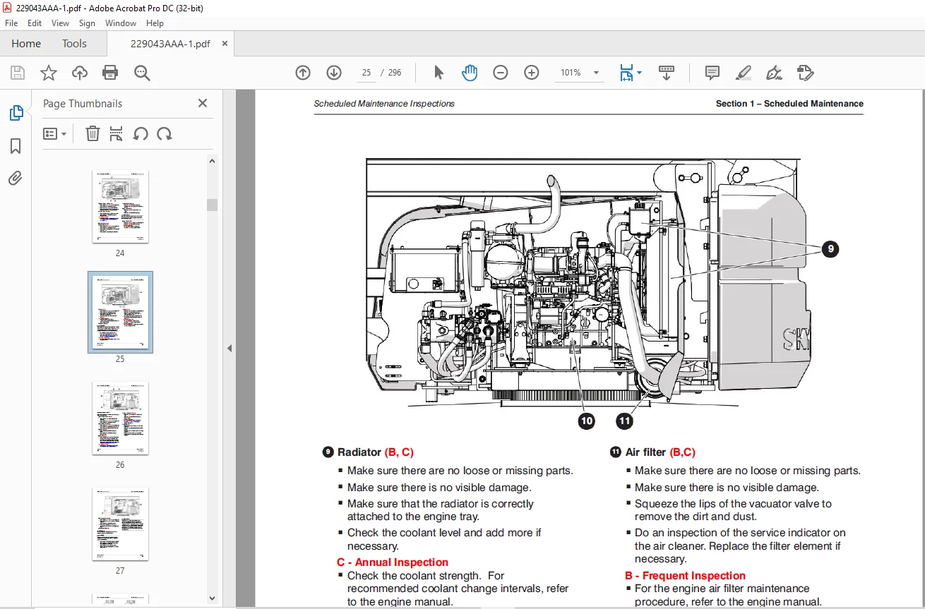
Scheduled Maintenance:
1.1 Read and Heed:
Skyjack is continuously improving and expanding product features on its equipment, therefore,
specifications and dimensions are subject to change without notice.
1.1 Read and Heed:
Skyjack is continuously improving and expanding product features on its equipment, therefore,
specifications and dimensions are subject to change without notice.
1.1-1 Mobile Elevating Work Platform (MEWP) Definition:
A MEWP is a mobile device that has a positionable platform supported from ground level by a
structure.
A MEWP is a mobile device that has a positionable platform supported from ground level by a
structure.
1.1-2 Purpose of Equipment:
The Skyjack Articulating Boom Series MEWPs are designed to transport and raise personnel, tools and
materials to overhead work areas.
The Skyjack Articulating Boom Series MEWPs are designed to transport and raise personnel, tools and
materials to overhead work areas.
1.1-3 Use of Equipment:
The MEWP is a highly maneuverable, mobile work station. Work platform elevation and elevated
driving must only be done on a firm surface.
The MEWP is a highly maneuverable, mobile work station. Work platform elevation and elevated
driving must only be done on a firm surface.
1.1-4 Manual:
Operating Manual: The operating manual is considered a fundamental part of the MEWP. It is a very
important way to communicate necessary safety information to users and operators. A complete
and legible copy of this manual must be kept in the provided weather-resistant storage compartment
on the MEWP at all times.
Service & Maintenance:
- The purpose of this is to provide the customer with the servicing and
maintenance procedures essential for the promotion of proper machine operation for its intended
purpose. - All information in this manual should be read and understood before any attempt is made to service
the machine.
1.1-5 Service Policy and Warranty:
Skyjack warrants each new product to be free of defective parts and workmanship for the first 2
years or 3000 hours, whichever occurs first. Any defective part will be replaced or repaired by
your local Skyjack dealer at no charge for parts or labor. In addition,
all products have a 5 year structural warranty. Contact the Skyjack Service Department for warranty
statement extensions or exclusions.
1.1-6 Operator Safety Reminders, Warnings and Precautions:
Operator safety is Skyjack’s priority. The operator should comply with all applicable
safety-related reminders, warnings and precautions found in the Operating Manual. They should be
read and understood completely before operating the MEWP.
Operator safety is Skyjack’s priority. The operator should comply with all applicable
safety-related reminders, warnings and precautions found in the Operating Manual. They should be
read and understood completely before operating the MEWP.
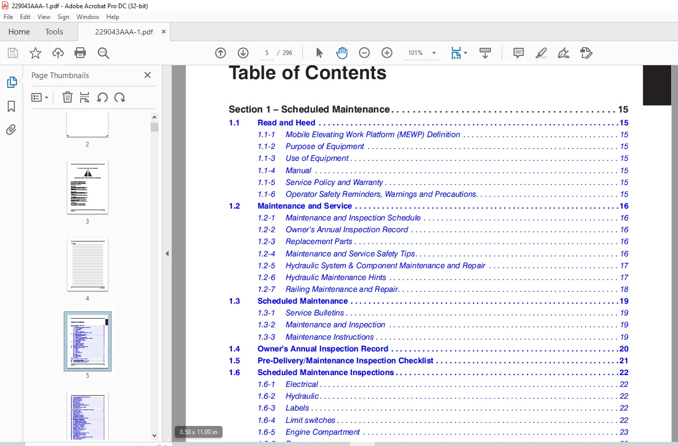
TABLE OF CONTENTS:
Skyjack SJ63 AJ+, SJ63 AJ Articulating Booms Service Manual 229043AAA – PDF DOWNLOAD
Table of Contents..........................................................................................................  5
Section 1 – Scheduled Maintenance.......................................................................................... 15
	1.1  Read and Heed..................................................................................................... 15
		1.1-1 Mobile Elevating Work Platform (MEWP) Definition............................................................. 15
		1.1-2 Purpose of Equipment......................................................................................... 15
		1.1-3 Use of Equipment............................................................................................. 15
		1.1-4 Manual....................................................................................................... 15
		1.1-5 Service Policy and Warranty.................................................................................. 15
		1.1-6 Operator Safety Reminders, Warnings and Precautions.......................................................... 15
	1.2  Maintenance and Service........................................................................................... 16
		1.2-1 Maintenance and Inspection Schedule.......................................................................... 16
		1.2-2 Owner’s Annual Inspection Record............................................................................. 16
		1.2-3 Replacement Parts............................................................................................ 16
		1.2-4 Maintenance and Service Safety Tips.......................................................................... 16
		1.2-5 Hydraulic System & Component Maintenance and Repair.......................................................... 17
		1.2-6 Hydraulic Maintenance Hints.................................................................................. 17
		1.2-7 Railing Maintenance and Repair............................................................................... 18
	1.3  Scheduled Maintenance............................................................................................. 19
		1.3-1 Service Bulletins............................................................................................ 19
		1.3-2 Maintenance and Inspection................................................................................... 19
		1.3-3 Maintenance Instructions..................................................................................... 19
	1.4  Owner’s Annual Inspection Record.................................................................................. 20
	1.5  Pre-Delivery/Maintenance Inspection Checklist..................................................................... 21
	1.6  Scheduled Maintenance Inspections................................................................................. 22
		1.6-1 Electrical................................................................................................... 22
		1.6-2 Hydraulic.................................................................................................... 22
		1.6-3 Labels (B)................................................................................................... 22
		1.6-4 Limit switches (B)........................................................................................... 22
		1.6-5 Engine Compartment........................................................................................... 23
		1.6-6 Base......................................................................................................... 28
		1.6-7 Platform .................................................................................................... 30
		1.6-8 Boom Assembly................................................................................................ 31
		1.6-9 Optional equipment (B)....................................................................................... 32
	1.7  Function Tests.................................................................................................... 33
Section 2 – Maintenance Tables and Diagrams................................................................................ 35
	2.1  Standard Hose Numbering System.................................................................................... 35
	2.2  Torque Specifications for Fasteners (US Imperial)................................................................. 37
	2.3  Torque Specifications for Fasteners (Metric)...................................................................... 38
	2.4  Torque Specifications for Hydraulic Couplings & Hoses............................................................. 39
	2.5  Axle Torque Specifications........................................................................................ 40
	2.6  Axles Maintenance Intervals....................................................................................... 41
	2.7  MEWP Torque Specifications........................................................................................ 42
	2.8  Maximum Platform Capacity......................................................................................... 43
	2.9  Tire Specifications............................................................................................... 43
	2.10  Floor Loading Pressure........................................................................................... 44
	2.11  Hydraulic Specifications & Gear Oil.............................................................................. 45
	2.12  Specifications & Features - Dimensions & Speeds.................................................................. 46
	2.13  Engine Specifications............................................................................................ 48
	2.14  Dimension and Reach Diagrams - SJ63AJ............................................................................ 49
	2.15  Axle Oscillation Diagrams........................................................................................ 50
Section 3 – System Component Identification and Schematics................................................................. 51
	3.1  Electrical Symbol Chart........................................................................................... 52
	3.2  Hydraulic Symbol Chart............................................................................................ 53
	3.3  Wire Number and Color Code........................................................................................ 54
	3.4  Hydraulic Parts List.............................................................................................. 55
	3.5  Electrical Component Parts List................................................................................... 59
	3.6  Rotary Manifold Port Identification............................................................................... 62
	3.7  Brake Manifold Port Identification................................................................................ 63
	3.8  Drive and System Pump and Port Identifications.................................................................... 64
	3.9  Drive Motor and Port Identifications.............................................................................. 65
	3.10  Jib Valve and Port Identifications............................................................................... 66
	3.11  Main Manifold and Port Identifications........................................................................... 67
	3.12  Main Manifold and Electrical Identifications..................................................................... 68
	3.13  Main Manifold and Hydraulic Identifications...................................................................... 69
	3.14  Main Electrical Harness  and Fuel Level Switch Harness........................................................... 70
	3.15  ECU Engine Wiring Diagram - Deutz................................................................................ 71
	3.16  Glow Plug Harnesses - Deutz D2011................................................................................ 72
	3.17  Glow Plug Harnesses - Deutz TD2.9L............................................................................... 73
	3.18  Engine Interface Harness - GM.................................................................................... 74
	3.19  Engine Interface Harness - Deutz TD2.9L.......................................................................... 75
	3.20  Lowering Throttle Valve Harness.................................................................................. 76
	3.21  Platform Harnesses............................................................................................... 77
	3.22  Platform Control Cables.......................................................................................... 78
	3.23  Limit Switch Connections at the Base Control Box................................................................. 79
	3.24  Load Sensing Connections - CE & AS............................................................................... 80
	3.25  All Motion Alarm Connections - CE & AS........................................................................... 81
	3.26  SGE Wiring Diagram............................................................................................... 82
	3.27  Hydraulic Generator and Oil Cooler Wiring - Base Control Box..................................................... 83
	3.28  Generator Wiring - Upper Control Box............................................................................. 84
	3.29  Welder Wiring - ANSI/CSA......................................................................................... 85
	3.30  Load Circuit Wiring.............................................................................................. 86
	3.31  Positive Air Shutoff Harness..................................................................................... 87
	3.32  Hydraulic Schematic - ANSI/CSA................................................................................... 88
	3.33  Hydraulic Schematic - CE & AS.................................................................................... 89
	3.34  Platform Control Box Wiring - ANSI/CSA........................................................................... 90
	3.35  Platform Conrol Box Wiring - CE - Deutz TCD2.2................................................................... 91
	3.36  Platform Control Box Wiring - CE - Deutz TD2.9L & D2011.......................................................... 92
	3.37  Platform Control Box Wiring - CE - Kubota WG2503................................................................. 93
	3.38  Platform Control Box Wiring - AS................................................................................. 94
	3.39  Base Control Box Wiring - ANSI/CSA............................................................................... 95
	3.40  Base Control Box Wiring - ANSI/CSA with Positive Air Shut-Off Option............................................. 96
	3.41  Base Control Box Wiring - CE - Deutz TCD2.2...................................................................... 97
	3.42  Base Control Box Wiring - CE - Deutz TD2.9L...................................................................... 98
	3.43  Base Control  Box Wiring - CE - Deutz D2011...................................................................... 99
	3.44  Base Control Box Wiring - AS.....................................................................................100
	3.45  Electrical Schematic - ANSI/CSA..................................................................................101
	3.46  Electrical Schematic - CE - Deutz TCD2.2.........................................................................102
	3.47  Electrical Schematic - CE - Deutz TD2.9..........................................................................103
	3.48  Electrical Schematic - CE - Deutz D2011..........................................................................104
	3.49  Electrical Schematic - CE - Kubota WG2503........................................................................105
	3.50  Electrical Schematic - AS - Deutz D2011..........................................................................106
	3.51  Engine Electrical Schematic - Deutz TD2.9L.......................................................................107
	3.52  Engine Interface Wiring - Deutz TD2.9L...........................................................................108
	3.53  Engine Electrical Schematic - Deutz D2011........................................................................109
	3.54  Engine Electrical Schematic - Kubota WG2503......................................................................110
	3.55  Engine Electrical Schematic - Deutz TCD2.2.......................................................................111
	3.56  Engine Interface Harness - Deutz TCD2.2..........................................................................112
Section 4 – Troubleshooting Information....................................................................................113
	4.1  Introduction......................................................................................................113
	4.2  Electrical System - ANSI/CSA......................................................................................114
		4.2-1 All Controls are Inoperative from the Base or Platform Console...............................................114
		4.2-2 All Controls are Inoperative from the Base Console...........................................................116
		4.2-3 The Engine will not Crank from the Base or Platform..........................................................116
		4.2-4 The Engine will not Crank from the Base......................................................................117
		4.2-5 The Engine will not Crank from the Platform..................................................................117
		4.2-6 The Boom Controls are Inoperative (Drive Operates)...........................................................117
		4.2-7 No Boom Up from the Base or Platform Controls................................................................118
		4.2-8 No Boom Up from the Base Console.............................................................................118
		4.2-9 No Boom Up from the Platform Console.........................................................................118
		4.2-10 No Boom Down from the Base or Platform Consoles.............................................................118
		4.2-11 No Boom Down from the Base Console..........................................................................119
		4.2-12 No Boom Down from the Platform Console......................................................................119
		4.2-13 No Turret Rotate Right from the Base or Platform Consoles...................................................119
		4.2-14 No Turret Rotate Right from the Base Console................................................................119
		4.2-15 No Turret Rotate Right from the Platform Console............................................................120
		4.2-16 No Turret Rotate Left from the Base or Platform Consoles....................................................120
		4.2-17 No Turret Rotate Left from the Base Console.................................................................120
		4.2-18 No Turret Rotate Left from the Platform Console.............................................................120
		4.2-19 No Riser Up from the Base or Platform Consoles..............................................................121
		4.2-20 No Riser Up from the Base Console...........................................................................121
		4.2-21 No Riser Up from the Platform Console.......................................................................121
		4.2-22 No Riser Down from the Base or Platform Consoles............................................................121
		4.2-23 No Riser Down from the Base Console.........................................................................122
		4.2-24 No Riser Down from the Platform Console.....................................................................122
		4.2-25 No Telescope Out from the Base or Platform Consoles.........................................................122
		4.2-26 No Telescope Out from the Base Console......................................................................122
		4.2-27 No Telescope Out from the Platform Console..................................................................123
		4.2-28 No Telescope In from the Base or Platform Consoles..........................................................123
		4.2-29 No Telescope In from the Base Console.......................................................................123
		4.2-30 No Telescope In from the Platform Console...................................................................123
		4.2-31 No Platform Level Up from the Base or Platform Consoles.....................................................124
		4.2-32 No Platform Level Up from the Base Console..................................................................124
		4.2-33 No Platform Level Up from the Platform Console..............................................................124
		4.2-34 No Platform Level Down from the Base or Platform Consoles...................................................124
		4.2-35 No Platform Level Down from the Base Console................................................................125
		4.2-36 No Platform Level Down from the Platform Console............................................................125
		4.2-37 No Platform Rotate or Jib Functions from the Base or Platform Consoles......................................125
		4.2-38 No Platform Rotate Right from the Base or Platform Consoles.................................................126
		4.2-39 No Platform Rotate Right from the Base Console..............................................................126
		4.2-40 No Platform Rotate Right from the Platform Console..........................................................126
		4.2-41 No Platform Rotate Left from the Base or Platform Consoles..................................................127
		4.2-42 No Platform Rotate Left from the Base Console...............................................................127
		4.2-43 No Platform Rotate Left from the Platform Console...........................................................127
		4.2-44 No Jib Up from the Base or Platform Consoles................................................................127
		4.2-45 No Jib Up from the Base Console.............................................................................128
		4.2-46 No Jib Up from the Platform Console.........................................................................128
		4.2-47 No Jib Down from the Base or Platform Consoles..............................................................128
		4.2-48 No Jib Down from the Base Console...........................................................................128
		4.2-49 No Jib Down from the Platform Console.......................................................................129
		4.2-50 No Drive or Steer Functions.................................................................................129
		4.2-51 No Forward or Reverse Drive.................................................................................129
		4.2-52 No Forward Drive............................................................................................129
		4.2-53 No Reverse Drive............................................................................................130
		4.2-54 The Brake will not Release..................................................................................130
		4.2-55 No Left Steer...............................................................................................130
		4.2-56 No Right Steer..............................................................................................131
		4.2-57 The Directon Sensing is Inoperative.........................................................................131
		4.2-58 The Load Sense Indicates Overload or Overload Warning with the Platform Empty or Below Weight...............132
		4.2-59 The Overload Indicator Light does not Turn On when the Platform is Overloaded...............................132
		4.2-60 The Audible Alarm does not Turn On with the Platform Overloaded.............................................132
	4.3  Electrical System - CE & AS.......................................................................................133
		4.3-1 All Controls are Inoperative.................................................................................133
		4.3-2 No Power To Platform.........................................................................................134
		4.3-3 No Power to Base.............................................................................................134
		4.3-4 The Engine Will Not Crank from the Base......................................................................135
		4.3-5 The Engine Will Not Crank from the Platform..................................................................135
		4.3-6 The Engine Will Not Crank from the Platform or Base (Deutz Diesel)...........................................135
		4.3-7 The Engine Will Not Crank from the Platform or Base when equipped with Elevate/Trackunit Telematics Ready....136
		4.3-8 The Engine Cranks but Will Not Start (Deutz Diesel)..........................................................137
		4.3-9 The Engine Will Not Crank from the Platform or Base Control (GM Dual Fuel)...................................137
		4.3-10 The Engine Cranks but Will Not Start (GM Dual Fuel).........................................................138
		4.3-11 The Glow Plug Circuit is Inoperative........................................................................140
		4.3-12 All Controls are Inoperative from the Base Console..........................................................141
		4.3-13 No Main Boom Down, Riser Down or Turret Rotate from Base Control Console....................................142
		4.3-14 No Boom Up from the Base Control Console....................................................................142
		4.3-15 No Boom Down from the Base Control Console..................................................................143
		4.3-16 No Riser Up from the Base Control Console...................................................................143
		4.3-17 No Riser Down from the Base Control Console.................................................................144
		4.3-18 No Turret Rotate Left from the Base Control Console.........................................................144
		4.3-19 No Turret Rotate Right from the Base Control Console........................................................145
		4.3-20 No Telescope Retract from the Base Control Console..........................................................145
		4.3-21 No Telescope Extend from the Base Control Console...........................................................146
		4.3-22 No Platform Rotate Left or Right............................................................................146
		4.3-23 Platform Rotates too Quickly................................................................................147
		4.3-24 No Platform Rotate Left from the Base Control Console.......................................................147
		4.3-25 No Platform Rotate Right from the Base Control Console......................................................148
		4.3-26 No Jib Up from the Base Control Console.....................................................................149
		4.3-27 No Jib Down from the Base Control Console...................................................................149
		4.3-28 No Manual Platform Level Up from the Base Control Console...................................................150
		4.3-29 No Manual Platform Level Down from the Base Control Console.................................................150
		4.3-30 All Controls are Inoperative from the Platform Control Console..............................................150
		4.3-31 No Boom Up from the Platform Control Console................................................................152
		4.3-32 No Boom Down from the Platform Control Console..............................................................152
		4.3-33 No Riser Up from the Platform Control Console...............................................................153
		4.3-34 No Riser Down from the Platform Control Console.............................................................154
		4.3-35 No Turret Left from the Platform Control Console............................................................155
		4.3-36 No Turret Right from the Platform Control Console...........................................................155
		4.3-37 No Toggle Switch Functions from the Platform Control Console................................................156
		4.3-38 No Telescope In from the Platform Control Console...........................................................156
		4.3-39 No Telescope Out from the Platform Control Console..........................................................157
		4.3-40 No Platform Rotate Left from the Platform Control Console...................................................158
		4.3-41 No Platform Rotate Right from the Platform Control Console..................................................159
		4.3-42 No Jib Up from the Platform Control Console.................................................................160
		4.3-43 No Jib Down from the Platform Control Console...............................................................161
		4.3-44 No Manual Platform Level Up from the Platform Control Console...............................................162
		4.3-45 No Manual Platform Level Down from the Platform Control Console.............................................163
		4.3-46 Mid Throttle Inoperative....................................................................................164
		4.3-47 High Throttle Inoperative...................................................................................165
		4.3-48 Brake will not Release......................................................................................166
		4.3-49 Differential Lock will not Engage...........................................................................166
		4.3-50 Differential Lock Engages Momentarily but will not stay Engaged.............................................167
		4.3-51 No Drive and Steer..........................................................................................167
		4.3-52  No Forward Drive...........................................................................................168
		4.3-53 No Reverse Drive............................................................................................168
		4.3-54 No High Speed Drive.........................................................................................169
		4.3-55 No Elevated Drive...........................................................................................170
		4.3-56 No Left Steer...............................................................................................171
		4.3-57 No Right Steer..............................................................................................171
		4.3-58 Direction Sensing Inoperative...............................................................................172
	4.4  Load Sensing System - CE & AS.....................................................................................173
		4.4-1 Green Power LED is not Flashing..............................................................................173
		4.4-2 Load Cell red Alarm LED is ON (with platform empty)..........................................................173
		4.4-3 Red Error LED is ON..........................................................................................173
		4.4-4 Load Cell red Alarm LED is OFF (with platform overloaded)....................................................173
		4.4-5 Platform Indicator Light does not turn ON....................................................................173
		4.4-6 Audible Alarm does not turn ON...............................................................................174
		4.4-7 Boom and Drive Functions are Enabled (with boom extended)....................................................174
	4.5  Hydraulic System - ANSI/CSA.......................................................................................175
		4.5-1 All Controls are Inoperative.................................................................................175
		4.5-2 All Boom Functions are Inoperative...........................................................................175
		4.5-3 No Main Boom Up..............................................................................................175
		4.5-4 No Main Boom Down............................................................................................175
		4.5-5 No Riser Boom Up.............................................................................................176
		4.5-6 No Riser Boom Down...........................................................................................176
		4.5-7 No Turret Rotate Left........................................................................................177
		4.5-8 No Turret Rotate Right.......................................................................................177
		4.5-9 No Boom Extend...............................................................................................178
		4.5-10 No Boom Retract.............................................................................................178
		4.5-11 No Jib Up...................................................................................................178
		4.5-12 No Jib Down.................................................................................................179
		4.5-13 No Platform Rotation Right..................................................................................179
		4.5-14 No Platform Rotation Left...................................................................................179
		4.5-15 The Platform will not Level Down Manually...................................................................180
		4.5-16 The Platform will not Level Up Manually.....................................................................180
		4.5-17 The Brake will not Release..................................................................................181
		4.5-18 The Brake will not Engage...................................................................................181
		4.5-19 The Differential Lock will not Engage.......................................................................182
		4.5-20 No Drive Forward or Reverse.................................................................................182
		4.5-21 No Forward Drive............................................................................................182
		4.5-22 No Reverse Drive............................................................................................182
		4.5-23 No High Speed Drive.........................................................................................183
		4.5-24 No Right Steer..............................................................................................183
		4.5-25 No Left Steer...............................................................................................183
		4.5-26 The Axle will not Oscillate.................................................................................183
		4.5-27 Axle Will Not Lock..........................................................................................184
	4.6  Hydraulic System - CE & AS........................................................................................185
		4.6-1 All Controls are Inoperative.................................................................................185
		4.6-2 All Boom Functions are Inoperative...........................................................................185
		4.6-3 No Main Boom Up..............................................................................................185
		4.6-4 No Main Boom Down............................................................................................185
		4.6-5 No Riser Boom Up.............................................................................................186
		4.6-6 No Riser Boom Down...........................................................................................186
		4.6-7 No Turret Rotate Left........................................................................................187
		4.6-8 No Turret Rotate Right.......................................................................................187
		4.6-9 No Boom Extend...............................................................................................188
		4.6-10 No Boom Retract.............................................................................................188
		4.6-11 No Jib Up...................................................................................................188
		4.6-12 Jib Up/ Down Slow...........................................................................................189
		4.6-13 No Jib Down.................................................................................................189
		4.6-14 No Platform Rotation Right..................................................................................189
		4.6-15 No Platform Rotation Left...................................................................................189
		4.6-16 Platform Rotates too Quickly................................................................................190
		4.6-17 Platform will not Level Down Manually.......................................................................190
		4.6-18 Platform will not Level Up Manually.........................................................................190
		4.6-19 Brake will not Release......................................................................................191
		4.6-20 Brake will not Engage.......................................................................................191
		4.6-21 Differential Lock will not Engage...........................................................................192
		4.6-22 No Drive Forward or Reverse.................................................................................192
		4.6-23 No Forward Drive............................................................................................192
		4.6-24 No Reverse Drive............................................................................................192
		4.6-25 No High Speed Drive.........................................................................................193
		4.6-26 No Right Steer..............................................................................................193
		4.6-27 No Left Steer...............................................................................................193
		4.6-28 The Axle Will Not Oscillate.................................................................................193
		4.6-29 The Axle Will Not Lock......................................................................................194
Section 5 – Procedures.....................................................................................................195
	5.1  General...........................................................................................................195
		5.1-1 Safety and Workmanship.......................................................................................195
	5.2  Platform..........................................................................................................196
		5.2-1 Human Machine Interface (HMI)................................................................................196
		5.2-2 User Interface Keys..........................................................................................196
		5.2-3 OCM Character Functions Charts...............................................................................197
		5.2-4 OCM Function Channel Names - CE & AS.........................................................................197
		5.2-5 OCM Operating Values Chart - CE & AS.........................................................................198
		5.2-6 How to Select Functionality - CE & AS........................................................................199
		5.2-7 How to View OCM Operation - CE & AS..........................................................................200
		5.2-8 How to Unlock and Modify OCM Settings - CE & AS..............................................................201
		5.2-9 OCM Pin Reference - ANSI/CSA.................................................................................202
		5.2-10 OCM Pin Voltage Reference - CE & AS.........................................................................208
		5.2-11 Platform Controller Voltage References......................................................................211
	5.3  Load Sensing System - CE & AS.....................................................................................213
		5.3-1 Load Sensing System Overload Status..........................................................................213
		5.3-2 Verify Proper Operation of the Load Sensing System...........................................................214
		5.3-3 Calibration of Load Sensing System (with “Teach In” Handset).................................................215
	5.4  Boom..............................................................................................................216
		5.4-1 Check Wear Pads..............................................................................................216
		5.4-2 Shim Wear Pads...............................................................................................216
		5.4-3 Cable Carrier Repair.........................................................................................216
		5.4-4 Rotary Actuator Bolt Torque Procedure........................................................................216
		5.4-5 Boom Section Wear Pad Replacement............................................................................217
		5.4-6 Platform and Jib Boom Removal................................................................................218
		5.4-7 Operating Machine Functions from the Base Controls...........................................................219
		5.4-8 Fly Boom Removal.............................................................................................219
		5.4-9 Change Wear Pads on Extension Cylinder Support...............................................................221
		5.4-10 Fly Boom Installation.......................................................................................222
		5.4-11 Platform/Jib Installation...................................................................................223
		5.4-12 Platform Control Console Connection.........................................................................223
		5.4-13 Extension Cylinder Removal..................................................................................224
		5.4-14 Extension Cylinder Installation.............................................................................227
		5.4-15 Main Boom Lift Cylinder Removal.............................................................................228
		5.4-16 Lift Cylinder Installation..................................................................................229
		5.4-17 Riser Cylinder Removal......................................................................................230
		5.4-18 Riser Cylinder Installation.................................................................................230
		5.4-19 Replace Limit Switch - Main Boom............................................................................231
		5.4-20 Test Main Boom Limit Switch.................................................................................232
		5.4-21 Replace Limit Switch - Riser Boom...........................................................................232
		5.4-22 Test Riser Boom Limit Switch................................................................................233
		5.4-23 Replace Limit Switch - Fly Boom.............................................................................233
		5.4-24 Test Fly Boom Limit Switch..................................................................................234
	5.5  Turret............................................................................................................235
		5.5-1 Check and Replace the High Pressure Filter...................................................................235
		5.5-2 Adjust the Turret Rotation Gear Backlash.....................................................................235
		5.5-3 Swing Drive Motor Removal....................................................................................236
		5.5-4 Check the Swing Drive Oil....................................................................................237
		5.5-5 Change the Swing Drive Oil...................................................................................237
		5.5-6 Check Rotation Bearing for Axial Wear........................................................................238
		5.5-7 Turret Rotation Gear Bolt Torque Sequence....................................................................238
		5.5-8 Electronic Tilt Switch Setup Procedure.......................................................................239
		5.5-9 Battery Replacement..........................................................................................241
	5.6  Deutz Diesel Engine...............................................................................................242
		5.6-1 Replace Engine Oil and Filter................................................................................242
		5.6-2 Replace the Fuel Filter......................................................................................243
		5.6-3 Replace the Air Filter.......................................................................................243
		5.6-4 Check the Engine Belt........................................................................................243
		5.6-5 Check the Oil Cooler (Deutz D2011 only)......................................................................243
		5.6-6 Deutz TD2.9L Fault Codes.....................................................................................244
	5.7  Kubota WG2503 Dual Fuel Engine....................................................................................264
		5.7-1 Engine Parameter Display (KAntrak 1700)......................................................................264
		5.7-2 Diagnostic Trouble Codes.....................................................................................265
		5.7-3 ECU Pin Reference Chart (Kubota WG2503)......................................................................270
		5.7-4 Fuse Box (Kubota WG2503).....................................................................................271
		5.7-5 MAP Sensor (Kubota WG2503)...................................................................................272
		5.7-6 IAT Sensor (Kubota WG2503)...................................................................................272
		5.7-7 ECT (Kubota WG2503)..........................................................................................273
		5.7-8 TPS & Engine Speed (Kubota WG2503)...........................................................................273
		5.7-9 Fuel Temperature Sensor (Kubota WG2503)......................................................................274
		5.7-10 Oil Pressure Sensor (Kubota WG2503).........................................................................274
	5.8  Hydraulic Tank....................................................................................................275
		5.8-1 Change the Hydraulic Tank Filter.............................................................................275
		5.8-2 Change the Hydraulic Oil.....................................................................................275
	5.9  Manifold and Hydraulic Pumps......................................................................................276
		5.9-1 Hydraulic Brake Pressure Adjustment..........................................................................276
		5.9-2 Hydraulic System Relief Valve Adjustment (RV1)...............................................................277
		5.9-3 Turret Rotate Relief Valve Adjustment (RV2)..................................................................277
		5.9-4 Platform Level Relief Valve Adjustment (RV3).................................................................278
		5.9-5 Riser Boom Down Relief Valve Adjustment (RV4)................................................................278
		5.9-6 Main Boom Down Relief Valve Adjustment (RV5).................................................................279
		5.9-7 Fly Boom Relief Valve Adjustment (RV6).......................................................................279
		5.9-8 Test Charge Pump Pressure on Drive Pump (RV10)...............................................................280
		5.9-9 Test Forward Drive Pressure on Drive Pump....................................................................280
		5.9-10 Test Reverse Drive Pressure on Drive Pump...................................................................281
		5.9-11 Hydraulic Standby Pressure Adjustment.......................................................................281
		5.9-12 Hydraulic High Pressure Adjustment..........................................................................282
	5.10  Axles............................................................................................................283
		5.10-1 Change the Oil in the Axles ................................................................................283
		5.10-2 Check the Oil Level in the Torque Hubs......................................................................283
		5.10-3 Change the Oil in the Torque Hubs...........................................................................283
		5.10-4 Check the Oil Level in the Axle Gearbox.....................................................................284
		5.10-5 Change the Oil in the Axle Gearbox..........................................................................284
		5.10-6 Oscillating Cylinder Bolt Replacement.......................................................................285
		5.10-7 Oscillating Cylinder Replacement............................................................................285
		5.10-8 Bleed the Oscillating Axle Cylinders........................................................................287
		5.10-9 Pin Brake Adjustments.......................................................................................287
		5.10-10 Brake Inspection...........................................................................................289
	5.11  Grease Points....................................................................................................290
		5.11-1 Grease the Turret Ring Gear.................................................................................290
		5.11-2 Grease the Turret Swing Drive...............................................................................290
		5.11-3 Grease the Axles............................................................................................291
		5.11-4 Grease the Drive Shaft......................................................................................291
	5.12  Options..........................................................................................................292
		5.12-1 Generator Troubleshooting...................................................................................292
		5.12-2 Generator Frequency/Voltage Check & Adjustment..............................................................293
IMAGES PREVIEW OF THE MANUAL:
Questions? Email us: [email protected]
https://vimeo.com/877762446?share=copy
PLEASE NOTE:
- This is the same manual used by the DEALERSHIPS to SERVICE your vehicle.
- The manual can be all yours – Once payment is complete, you will be taken to the download page from where you can download the manual. All in 2-5 minutes time!!
- Need any other service / repair / parts manual, please feel free to contact us at heydownloadss @gmail.com . We may surprise you with a nice offer
S.V