Trusted Business
Verified & Licensed
Virus Free Files
100% Safe Downloads
Secure Payment
SSL Protected
Instant Delivery
Available Immediately
Skyjack SJ63AJ Articulating Boom Parts Manual 170948AH – PDF DOWNLOAD
$28.95
Skyjack SJ63AJ Articulating Boom Parts Manual 170948AH – PDF DOWNLOAD
SJ63AJ: 95300481 to 95399999
Instant PDF Download
Available immediately
Save to Your Device
Download & keep forever
Antivirus Scanned
100% virus-free
Trusted Worldwide
175,000+ customers
Description
Skyjack SJ63AJ Articulating Boom Parts Manual 170948AH – PDF DOWNLOAD
FILE DETAILS:
Skyjack SJ63AJ Articulating Boom Parts Manual 170948AH – PDF DOWNLOAD
Language : English
Pages : 328
Downloadable : Yes
File Type : PDF
IMAGES PREVIEW OF THE MANUAL:
DESCRIPTION:
Skyjack SJ63AJ Articulating Boom Parts Manual 170948AH – PDF DOWNLOAD
SJ63AJ: 95300481 to 95399999
Foreword:
General:
The information contained in this manual is designed to aid the user in locating and identifying
replacement parts. Component parts of various assemblies and subassemblies comprising the work
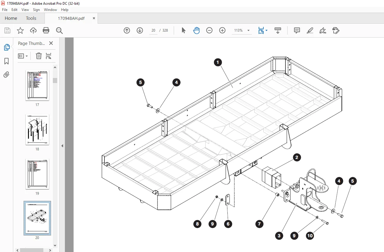
platform are illustrated and accompanied by a descriptive parts list. Exploded drawings are used to
show relative location of component parts in disassembly order. If a part cannot be found in this
manual, contact your local Skyjack Parts Department for assistance.
General:
The information contained in this manual is designed to aid the user in locating and identifying
replacement parts. Component parts of various assemblies and subassemblies comprising the work
platform are illustrated and accompanied by a descriptive parts list. Exploded drawings are used to
show relative location of component parts in disassembly order. If a part cannot be found in this
manual, contact your local Skyjack Parts Department for assistance.
Parts Ordering Information:
When ordering replacement parts, the complete part number and description should be used to ensure
proper identification and delivery of the desired item. This complete identification should also be
used when requesting equipment information.
proper identification and delivery of the desired item. This complete identification should also be
used when requesting equipment information.
Method of Listing:
Parts are listed in order according to the reference number shown in the illustration, followed by
a full description based upon the “NOUN FIRST” method. That is, the noun name of the part is listed
first, then the modifying description information which serves to specifically identify the item.
For example: PIN, Clevis.
Assemblies at the beginning of a parts list may be identified with a reference letter: A, B, C,
etc. These letters are used to identify different configurations of the assembly. Individual parts
in these lists have
corresponding letters after their description to identify which assembly it is used in. If a part
does not have a reference letter, it is used in all of the assemblies.
Bullets (•) are used to show the assembly structure,
or parent/child relationship. A part listed at the beginning of the parts list without a bullet
before the description is the main assembly, and all of the parts below it with one bullet are the
subcomponent parts of that assembly. Two bullets denote a subcomponent of a subcomponent, etc.
Example:
Main Assembly A
• Part 1 (subcomponent of Main Assembly A)
• Part 2 (subcomponent of Main Assembly A)
• • Part 3 (subcomponent of Part 2)
Quantities:
The quantities required to complete the assembly are given for each part. If the quantity is (AR),
it is understood that the quantity may vary when the machine is equipped with certain options.
Order quantity as needed.
The quantities required to complete the assembly are given for each part. If the quantity is (AR),
it is understood that the quantity may vary when the machine is equipped with certain options.
Order quantity as needed.
How To Order Repair Parts:
1 . Address all orders to your local SKYJACK dealer.
2 . Specify model and serial number of the work platform (found on the serial number plate).
3 . List the quantity needed.
4 . List the length needed (if it is a bulk item).
5 . List the part number and description as shown in this manual for each item.
6 . Show the billing and shipping address and the name of the individual, if possible.
7 . Suggest the best routing.
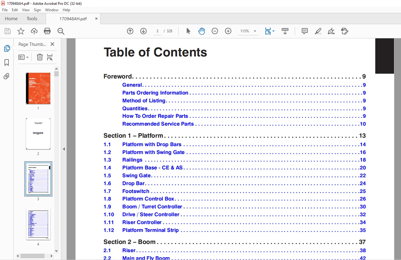
TABLE OF CONTENTS:
Skyjack SJ63AJ Articulating Boom Parts Manual 170948AH – PDF DOWNLOAD
Table of Contents...........................................  3
Recommended Service Parts................................... 10
Foreword....................................................  9
	General.................................................  9
	Parts Ordering Information..............................  9
	Method of Listing.......................................  9
	Quantities..............................................  9
	How To Order Repair Parts...............................  9
	Recommended Service Parts............................... 10
Section 1 – Platform........................................ 13
	1.1  Platform with Drop Bars............................ 14
	1.2  Platform with Swing Gate........................... 16
	1.3  Railings........................................... 18
	1.4  Platform Base - CE & AS............................ 20
	1.5  Swing Gate......................................... 22
	1.6  Drop Bar........................................... 24
	1.7  Footswitch......................................... 25
	1.8  Platform Control Box............................... 26
	1.9  Boom / Turret Controller........................... 30
	1.10  Drive / Steer Controller.......................... 32
	1.11  Riser Controller.................................. 34
	1.12  Platform Terminal Strip........................... 35
Section 2 – Boom............................................ 37
	2.1  Riser.............................................. 38
	2.2  Main and Fly Boom.................................. 42
	2.3  Fly Boom........................................... 46
	2.4  Upper Pivot........................................ 47
	2.5  Cable Track........................................ 48
	2.6  Jib................................................ 50
	2.7  Limit Switches..................................... 52
	2.8  Rotary Actuator.................................... 54
Section 3 – Cylinders....................................... 55
	3.1  Riser Lift Assembly................................ 56
	3.2  Riser Cylinder..................................... 57
	3.3  Lift Cylinder...................................... 58
	3.4  Master Cylinder.................................... 59
	3.5  Slave Cylinder..................................... 60
	3.6  Axle Lock Cylinder................................. 61
	3.7  Extension Cylinder................................. 62
	3.8  Jib Cylinder....................................... 64
Section 4 – Turret.......................................... 67
	4.1  Turret............................................. 68
	4.2  Cowling Mounting - Engine Side..................... 70
	4.3  Cowling Mounting - Controls Side................... 72
	4.4  Cowling - Engine Side.............................. 74
	4.5  Cowling - Controls Side............................ 75
	4.6  Counterweight...................................... 76
	4.7  Additional Counterweight........................... 77
	4.8  Engine Tray........................................ 78
	4.9  Main Manifold...................................... 80
	4.10  Brake Manifold.................................... 84
	4.11  Fuel Tank - Diesel................................ 86
	4.12  Fuel Tank - Gasoline.............................. 88
	4.13  Hydraulic Tank.................................... 90
	4.14  High Pressure Filter.............................. 92
	4.15  Swing Drive....................................... 93
	4.16  Base Controls..................................... 94
	4.17  Base Terminal Strip - ANSI/CSA & AS...............100
	4.18  Base Terminal Strip - CE..........................101
	4.19  Emergency Power Unit..............................102
	4.20  Battery...........................................103
	4.21  High Pressure Shuttle Valve.......................104
	4.22  Grease Line.......................................105
Section 5 – Base............................................107
	5.1  Base...............................................108
	5.2  Axle Hardware - Front..............................110
	5.3  Axle Hardware - Rear...............................111
	5.4  Front Axle.........................................112
	5.5  Differential - Front...............................116
	5.6  Central Housing - Front............................118
	5.7  Steering...........................................119
	5.8  Trunnion - Front...................................120
	5.9  Drive Shaft........................................121
	5.10  Rear Axle.........................................122
	5.11  Differential - Rear...............................124
	5.12  Central Housing - Rear............................126
	5.13  Gear Box..........................................128
	5.14  Brakes............................................130
	5.15  Rotary Manifold...................................134
	5.16  Propane Tank......................................136
	5.17  Tires.............................................138
Section 6 – Engines.........................................141
	6.1  Engine - Deutz TD2.9L..............................142
	6.2  Radiator - Deutz TD2.9L............................146
	6.3  Air Intake - Deutz TD2.9L..........................148
	6.4  Engine - Deutz TCD2.2..............................150
	6.5  Radiator - Deutz TCD2.2............................154
	6.6  Air Intake - Deutz TCD2.2..........................158
	6.7  Engine - Deutz D2011...............................160
	6.8  Engine - Perkins 2.2TA.............................164
	6.9  Air Intake - Perkins 2.2TA.........................172
	6.10  Radiator - Perkins 2.2TA..........................174
	6.11  Engine - GM 3.0L..................................178
	6.12  Engine - Kubota WG2503............................182
	6.13  Radiator & Air Intake - Kubota WG2503.............188
	6.14  Drive & System Pumps..............................192
	6.15  Engine Coupling - Deutz...........................194
	6.16  Engine Coupling - Kubota..........................195
	6.17  Engine Coupling - Perkins.........................196
Section 7 – Electrical Harnesses............................197
	7.1  Main Electrical and Fuel Level Switch Harnesses....198
	7.2  Lowering Throttle Valve Harness....................200
	7.3  Rotate Select Harness..............................201
	7.4  Cable Harnesses....................................202
	7.5  Control Cables.....................................204
	7.6  Outlet - 110/220 V.................................205
	7.7  ECU Harness - Deutz................................206
	7.8  Glow Plug Harness - Deutz TD2.9L...................207
	7.9  Glow Plug Harness - Deutz TCD2.2...................208
	7.10  Glow Plug Harness - Deutz D2011...................209
	7.11  Engine Interface Harness - GM.....................210
	7.12  Engine Interface Harness - Kubota WG2503..........212
	7.13  Engine Interface Harness - Deutz TD2.9L...........214
	7.14  Engine Interface Harness - Deutz TCD2.2...........216
	7.15  Fuse Box - Perkins 2.2TA..........................220
	7.16  Differential Lock Valve Harness...................222
Section 8 – Hose Connections................................223
	8.1  Hose Numbering System..............................224
	8.2  Hydraulic Hoses - Turret...........................226
	8.3  Hydraulic Hoses - Chassis..........................228
	8.4  Hydraulic Hoses - Drive & System Pumps.............230
	8.5  Hydraulic Hoses - Booms............................232
	8.6  Fuel Lines - Deutz TD2.9L..........................234
	8.7  Fuel Lines - Deutz D2011...........................235
	8.8  Fuel Lines - Perkins 2.2TA.........................236
	8.9  Fuel Lines - GM 3.0L...............................238
	8.10  Fuel Lines - Kubota WG2503........................240
Section 9 – Optional Equipment..............................243
	9.1  Diesel Scrubber....................................244
	9.2  All Motion Alarm...................................245
	9.3  Air Hose to Platform...............................246
	9.4  Hostile Environment Kit............................248
	9.5  Control Box Cover..................................250
	9.6  Hydraulic Oil Cooler...............................252
	9.7  Hoses  - Hydraulic Oil Cooler......................253
	9.8  Oil Cooler Wiring..................................254
	9.9  Generator - 3.5 kW.................................256
	9.10  Generator - 12 kW.................................260
	9.11  Generator - 7.5 kW................................262
	9.12  Hoses - 3.5 kW Generator..........................264
	9.13  Hoses - 12 kW Generator...........................265
	9.14  Hoses - 7.5 kW Generator..........................266
	9.15  Generator Wiring..................................268
	9.16  Welder & Mount....................................270
	9.17  Cold Start........................................274
	9.18  Block Heater......................................275
	9.19  Arctic Package....................................276
	9.20  Load Circuit......................................278
	9.21  Glazier Package...................................280
	9.22  External Railing..................................282
	9.23  Pipe Rack.........................................284
	9.24  SGM...............................................286
	9.25  SGE...............................................288
	9.26  Tool Caddy........................................290
	9.27  Work Lights.......................................292
	9.28  Half-Height Platform Mesh.........................294
	9.29  Positive Air Shut-off Valve - Deutz TD2.9L........298
	9.30  Positive Air Shutt-off Valve - Deutz D2011........300
	9.31  Residual Current Device (RCD).....................302
	9.32  Oil Quick Drain...................................303
	9.33  Elevate Telematics................................304
	9.34  Elevate Telematics Subscription...................312
	9.35  Flashing Light....................................313
Section 10 – Labels.........................................315
	10.1  Label Kits........................................316
	10.2  Labels - Platform Control Box.....................317
	10.3  Labels - Engine Side..............................318
	10.4  Labels - Controls Side............................320
	10.5  Labels - Controls Compartment.....................322
	10.6  Labels - Engine Compartment.......................323
	10.7  Labels - Platform.................................324
	10.8  Labels - Front & Back.............................326
Customer Support: [email protected]
PLEASE NOTE:
- This is the SAME MANUAL used by the dealerships to diagnose your vehicle
- No waiting for couriers / posts as this is a PDF manual and you can download it within 2 minutes time once you make the payment.
- Your payment is all safe and the delivery of the manual is INSTANT – You will be taken to the DOWNLOAD PAGE.
- So have no hesitations whatsoever and write to us about any queries you may have : heydownloadss @gmail.com
S.V