Skyjack SJ6826 RT SJ6832 RT Compact Rough Terrain Scissors Service Manual 143899AE – PDF DOWNLOAD
$28.95
Skyjack SJ6826 RT SJ6832 RT Compact Rough Terrain Scissors Service Manual 143899AE – PDF DOWNLOAD
SJ 68XXRT 37,002,164 to 37,002,787
Description
Skyjack SJ6826 RT SJ6832 RT Compact Rough Terrain Scissors Service Manual 143899AE – PDF DOWNLOAD
FILE DETAILS:
Skyjack SJ6826 RT SJ6832 RT Compact Rough Terrain Scissors Service Manual 143899AE – PDF DOWNLOAD
Language : English
Pages : 154
Downloadable : Yes
File Type : PDF
DESCRIPTION:
Skyjack SJ6826 RT SJ6832 RT Compact Rough Terrain Scissors Service Manual 143899AE – PDF DOWNLOAD
SKYJACK is continuously improving and expanding product features on its equipment, therefore, specifications
and dimensions are subject to change without notice.
Aerial Platform Definition:
A mobile device that has an adjustable position platform supported from ground level by a structure.
Purpose of Equipment:
The SKYJACK Rough Terrain’s mid and full size aerial platforms are designed to transport and raise personnel, tools
and materials to overhead work areas.
Use of Equipment:
The aerial platform is a highly maneuverable, mobile work station. Lifting and driving must be on a flat, level,
compacted surface. It can be driven over uneven terrain only when the platform is fully lowered.
Manuals:
Operating:
The operating manual is considered a fundamental part of the aerial platform. It is a very important way to
communicate necessary safety information to users and operators. A complete and legible copy of this manual
must be kept in the provided weather-resistant storage compartment on the aerial platform at all times.
Service & Maintenance
The purpose of this is to provide the customer with the servicing and maintenance procedures essential for
the promotion of proper machine operation for its intended purpose.
All information in this manual should be read and understood before any attempt is made to service the machine.
The updated copy of the manuals are found on the company’s website: www.skyjack.com.
Operator:
The operator must read and completely understand both this operating manual and the safety panel label located
on the platform and all other warnings in this manual and on the aerial platform. Compare the labels on the aerial
platform with the labels found within this manual. If any labels are damaged or missing, replace them immediately.
Service Policy and Warranty:
SKYJACK warrants each new SJRT series work platform to be free of defective parts and workmanship for the first
24 months. Any defective part will be replaced or repaired by your local SKYJACK dealer at no charge for parts or
labor. Contact the SKYJACK Service Department for warranty statement extensions or exclusions.
Optional Accessories:
The SKYJACK aerial platform is designed to accept a variety of optional accessories. These are listed under “Standard
and Optional Features” in Table 2.1 of the operating manual. Operating instructions for these options (if equipped)
are located in section 2 of the operating manual.
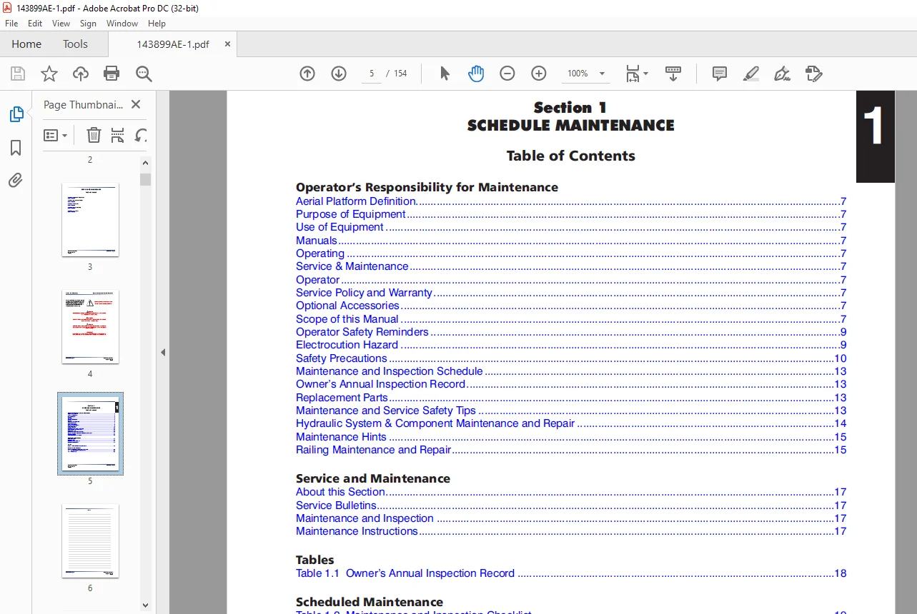
TABLE OF CONTENTS:
Skyjack SJ6826 RT SJ6832 RT Compact Rough Terrain Scissors Service Manual 143899AE – PDF DOWNLOAD
Cover.......................................................................................................................................................  1
ToC.........................................................................................................................................................  1
Section 1 - Scheduled Maintenance...........................................................................................................................  1
	Operator’s Responsibility for Maintenance...............................................................................................................  6
		Aerial Platform Definition..........................................................................................................................  7
		Purpose of Equipment................................................................................................................................  7
		Use of Equipment....................................................................................................................................  7
		Manuals.............................................................................................................................................  7
		Operating...........................................................................................................................................  7
		Service & Maintenance...............................................................................................................................  7
		Operator............................................................................................................................................  7
		Service Policy and Warranty.........................................................................................................................  7
		Optional Accessories................................................................................................................................  7
		Scope of this Manual................................................................................................................................  7
		Operator Safety Reminders...........................................................................................................................  9
		Electrocution Hazard................................................................................................................................  9
		Safety Precautions.................................................................................................................................. 10
		Maintenance and Inspection Schedule................................................................................................................. 13
		Owner’s Annual Inspection Record.................................................................................................................... 13
		Replacement Parts................................................................................................................................... 13
		Maintenance and Service Safety Tips................................................................................................................. 13
		Hydraulic System & Component Maintenance and Repair................................................................................................. 14
		Maintenance Hints................................................................................................................................... 15
		Railing Maintenance and Repair...................................................................................................................... 15
	Service and Maintenance................................................................................................................................. 17
		About this Section.................................................................................................................................. 17
		Service Bulletins................................................................................................................................... 17
		Maintenance and Inspection.......................................................................................................................... 17
		Maintenance Instructions............................................................................................................................ 17
	Tables.................................................................................................................................................. 18
		Table 1.1  Owner’s Annual Inspection Record......................................................................................................... 18
	Scheduled Maintenance................................................................................................................................... 19
		Table 1.2  Maintenance and Inspection Checklist..................................................................................................... 19
		1.1 Scheduled Maintenance Inspections............................................................................................................... 20
		1.2 Function Tests.................................................................................................................................. 31
Section 2 - Maintenance Tables and Diagrams................................................................................................................. 41
	Tables.................................................................................................................................................. 41
		Table 2.1a  Specifications and Features - ANSI/CSA.................................................................................................. 42
		Table 2.1b  Specifications and Features - CE........................................................................................................ 43
		Table 2.1c  Specifications and Features - AS........................................................................................................ 44
		Table 2.2a  Floor Loading Pressure - ANSI/CSA....................................................................................................... 46
		Table 2.2b  Floor Loading Pressure - CE............................................................................................................. 46
		Table 2.2c  Floor Loading Pressure - AS............................................................................................................. 47
		Table 2.3a  Maximum Platform Capacities (Evenly Distributed) - ANSI/CSA............................................................................. 48
		Table 2.3b  Maximum Platform Capacities (Evenly Distributed) - CE................................................................................... 48
		Table 2.3c  Maximum Platform Capacities (Evenly Distributed) - AS................................................................................... 49
		Table 2.4  Rough Terrain Scissor Fluids............................................................................................................. 50
		Table 2.5  Torque Specifications.................................................................................................................... 52
Section 3 - System Component Identification and Schematics.................................................................................................. 53
	Charts.................................................................................................................................................. 53
		3.1.  Hydraulic Symbol Chart........................................................................................................................ 55
		3.2.  Electrical Symbol Chart....................................................................................................................... 56
	Parts List.............................................................................................................................................. 56
		3.3.  Hydraulic Schematic Parts List................................................................................................................ 57
		3.4.  Electrical Parts List ........................................................................................................................ 60
	Diagrams and Schematics................................................................................................................................. 64
		3.5.  Hydraulic Schematic........................................................................................................................... 65
		3.6.  Hydraulic Manifolds And Ports Identification.................................................................................................. 66
		3.7.  Control Box Diagram - With All Options........................................................................................................ 68
		3.8.  Outrigger/Hydraulic Generator Control Console Wiring.......................................................................................... 69
		3.9.  Scissor Arm Control Cable..................................................................................................................... 70
		3.10.  Main Manifold Harness Wiring Diagram - ANSI/CSA.............................................................................................. 71
		3.11.  Main Manifold Harness Wiring Diagram - CE.................................................................................................... 72
		3.12.  Load Sensing Harnesses....................................................................................................................... 73
		3.13.  Engine Wiring Diagram - Dual Fuel System (Kubota Engine)..................................................................................... 74
		3.14a.  Engine Wiring Diagram - Diesel Fuel System (Kubota Engine).................................................................................. 75
		3.14b.  Engine Wiring Diagram - Diesel Fuel System (Kubota Engine).................................................................................. 76
		3.15.  Outrigger Optional Harness Diagram........................................................................................................... 77
		3.16.  Hydraulic Generator Electrical Panel Assembly................................................................................................ 78
		3.17.  Electrical Panel Wiring Diagram - Terminal Block Details..................................................................................... 79
		3.18.  Electrical Panel Wiring Diagram (ANSI/CSA)................................................................................................... 81
		3.19.  Electrical Panel Wiring Diagram (CE)......................................................................................................... 82
		3.20.  Electrical Schematic - ANSI/CSA (No  Option With Kubota Dual Fuel Engine).................................................................... 83
		3.21.  Electrical Schematic - ANSI/CSA (All  Option With Kubota Dual Fuel Engine)................................................................... 84
		3.22a.  Electrical Schematic - ANSI/CSA (All Option With Kubota Diesel Engine)...................................................................... 85
		3.22b.  Electrical Schematic - ANSI/CSA (All Option With Kubota Diesel Engine)...................................................................... 86
		3.23a.  Electrical Schematic - CE (All Option With Kubota Diesel Engine)............................................................................ 87
		3.23b.  Electrical Schematic - CE (All Option With Kubota Diesel Engine)............................................................................ 88
Section 4 - Troubleshooting Information..................................................................................................................... 89
	Electrical System....................................................................................................................................... 89
		4.1-1 All Controls Inoperative...................................................................................................................... 93
		4.1-2 No Power To Platform.......................................................................................................................... 93
		4.1-3    All Functions Inoperative (Machines Equipped with Load Sensing System) (CE)................................................................ 94
		4.1-4 All Functions Inoperative from The Platform................................................................................................... 94
		4.1-5 Engine Will Not Crank from Platform or Base Control Console................................................................................... 94
		4.1-6 Engine Cranks But Will Not Start - Kubota Diesel.............................................................................................. 95
		4.1-7 Engine Cranks But Will Not Start - Kubota Dual Fuel........................................................................................... 95
		4.1-8 Glow Plugs Inoperative from Engine Controls or Platform (Diesel Models)....................................................................... 96
		4.1-9 Choke Inoperative from Engine Controls or Platform (Kubota Dual Fuel)......................................................................... 97
		4.1-10 High Throttle Inoperative.................................................................................................................... 97
		4.1-11 High Throttle On Demand Inoperative (Kubota Dual Fuel)....................................................................................... 98
		4.1-12 Drive and Steer Inoperative (Machines without outriggers option)............................................................................. 98
		4.1-13 Drive and Steer Inoperative (Machines with outriggers option)................................................................................ 99
		4.1-14 Brakes Will Not Release......................................................................................................................100
		4.1-15 Steer Right Inoperative......................................................................................................................100
		4.1-16 Steer Left Inoperative.......................................................................................................................100
		4.1-17 Reverse Drive Inoperative....................................................................................................................101
		4.1-18 Forward Drive Inoperative....................................................................................................................101
		4.1-19 First Drive Speed and Steering Inoperative...................................................................................................102
		4.1-20 Second Drive Speed Inoperative...............................................................................................................102
		4.1-21 Third Drive Speed Inoperative................................................................................................................104
		4.1-22 High Drive Speed Inoperative.................................................................................................................104
		4.1-23 Up Circuit Inoperative from Platform.........................................................................................................104
		4.1-24 Up Circuit Inoperative from Base Control Console.............................................................................................105
		4.1-25 Up Circuit Inoperative from Platform or Base Control Console (without Outriggers)............................................................105
		4.1-26 Platform will Not Lift from Platform or Base Control Console with Outriggers Retracted (Lift Operates Correctly with Outriggers Extended)....105
		4.1-27 Platform will Not Lift from Platform or Base Control Console with Outriggers Extended........................................................106
		4.1-28 Platform will Not Lift from Platform or Base Control Console with Outriggers Extended or Retracted...........................................107
		4.1-29 Down Circuit Inoperative from Platform.......................................................................................................107
		4.1-30 Down Circuit Inoperative from Base...........................................................................................................108
		4.1-31   No Down Function (Additional for machines with Load Sensing System) (CE)...................................................................108
		4.1-32 Hydraulic Generator Inoperative..............................................................................................................108
		4.1-33 Hydraulic Generator will not Shut Off from Generator Switch..................................................................................109
		4.1-34 All Outriggers Inoperative (Auto-Level and Manual)...........................................................................................110
		4.1-35 All Outriggers Inoperative  (Auto-Level and Manual from Platform Controls)...................................................................110
		4.1-36 All Outriggers Inoperative (Base Controls only)..............................................................................................110
		4.1-37 All Outriggers Inoperative (Auto Level only).................................................................................................111
		      A: Led Power Indicator Light at Outrigger Control Module (OCM1) Not On (Constant).............................................................111
		4.1-38 All Outriggers Inoperative (Auto Level only).................................................................................................112
		      B: Led Power Indicator Light at Outrigger Control Module (OCM1) Flashing......................................................................112
		4.1-39 Left Front Outrigger Inoperative Manually....................................................................................................113
		4.1-40 Right Front Outrigger Inoperative Manually...................................................................................................113
		4.1-41 Right Rear Outriggers Inoperative Manually...................................................................................................113
		4.1-42 Left Rear Outriggers Inoperative Manually....................................................................................................113
		4.1-43 Individual Outrigger Functions Inoperative (Auto-Level) .....................................................................................114
		4.1-44 Auto-Level Inoperative.......................................................................................................................114
		4.1-45 Auto All Up Inoperative (Retract)............................................................................................................114
	Hydraulic System........................................................................................................................................115
		4.2-1 All Functions Inoperative ....................................................................................................................115
		4.2-2 Steering Inoperative..........................................................................................................................115
		4.2-3 Lift, Steer and First Drive Speed Inoperative.................................................................................................115
		4.2-4 Second Drive Speed Inoperative................................................................................................................115
		4.2-5 Drive Inoperative.............................................................................................................................115
		4.2-6 Drive Sluggish................................................................................................................................116
		4.2-7 Reverse Drive Inoperative.....................................................................................................................116
		4.2-8 Forward Drive Inoperative.....................................................................................................................116
		4.2-9 Drive Inoperative When in Low Drive...........................................................................................................116
		4.2-10 Drive Inoperative When in High Drive.........................................................................................................116
		4.2-11 Brakes Will Not Release......................................................................................................................116
		4.2-12 Up Circuit Inoperative.......................................................................................................................116
		4.2-13 Down Circuit Inoperative.....................................................................................................................117
		4.2-14 Hydraulic Generator Inoperative..............................................................................................................117
		4.2-15 All Outriggers Inoperative...................................................................................................................117
		4.2-16 Left Front Outriggers Inoperative............................................................................................................117
		4.2-17 Right Front Outriggers Inoperative...........................................................................................................117
		4.2-18 Right Rear Outriggers Inoperative............................................................................................................117
		4.2-19 Left Rear Outriggers Inoperative.............................................................................................................117
		4.2-20 Outriggers Drift In..........................................................................................................................118
		Load Sense System Flash Codes.......................................................................................................................119
		4.3-1 Flash Code F01:  Check HWFS...................................................................................................................119
		4.3-2 Flash Code F02:  Not Ground Mode..............................................................................................................119
		4.3-3 Flash Code F03:  Not Stopped..................................................................................................................119
		4.3-4 Flash Code F04:  Tilted.......................................................................................................................119
		4.3-5 Flash Code F05:  Bad Height...................................................................................................................119
		4.3-6 Flash Code F06:  Check Elev...................................................................................................................119
		4.3-7 Flash Code F08:  Check Elev...................................................................................................................119
		4.3-8 Flash Code F09:  Bad Height...................................................................................................................119
		4.3-9 Flash Code F10:  Bad Height...................................................................................................................119
		4.3-10 Flash Code F11:  Not Up......................................................................................................................119
		4.3-11 Flash Code F12:  Too Many....................................................................................................................120
		4.3-12 Flash Code F13:  Low Height Range............................................................................................................120
		4.3-13 Flash Code F14:  Bad Height..................................................................................................................120
		4.3-14 Flash Code F15:  Check Elev..................................................................................................................120
		4.3-15 Flash Code F16:  Low Elev.open...............................................................................................................120
		4.3-16 Flash Code F17:  High Elev.open..............................................................................................................120
		4.3-17 Flash Code F18:  Low Elev.close..............................................................................................................120
		4.3-18 Flash Code F19:  High Elev.close.............................................................................................................121
		4.3-19 Flash Code F20:  Height<>0%..................................................................................................................121
		4.3-20 Flash Code F21:Height<>0%....................................................................................................................121
		4.3-21 Flash Code F22:Height<>100%..................................................................................................................121
		4.3-22 Flash Code F23:Height<>100%..................................................................................................................121
		4.3-23 Flash Code F24:Too Many......................................................................................................................121
		4.3-24 Flash Code F25:Check Elev....................................................................................................................121
		4.3-25 Flash Code F26:Check Elev....................................................................................................................121
		4.3-26 Flash Code F27:Bad Height....................................................................................................................121
		4.3-27 Flash Code F30:Bad Heights...................................................................................................................122
		4.3-28 Flash Code F31:Reject Curve..................................................................................................................122
		4.3-29 Flash Code F32:Reject Curve..................................................................................................................122
		4.3-30 Flash Code F33:Reject Curve..................................................................................................................122
		4.3-31 Flash Code F34:Reject Curve..................................................................................................................122
		4.3-32 Flash Code F40:Reject Delta..................................................................................................................122
		4.3-33 Flash Code F42:Low Pressure..................................................................................................................122
		4.3-34 Flash Code F43:High Pressure.................................................................................................................122
		4.3-35 Flash Code F44:Low Pressure..................................................................................................................122
		4.3-36 Flash Code F45:High Pressure.................................................................................................................123
		4.3-37 Flash Code F46:Check Elev....................................................................................................................123
		4.3-38 Flash Code F47:Check Elev....................................................................................................................123
		General.............................................................................................................................................127
		Safety and Workmanship..............................................................................................................................127
Section 5 - Procedures......................................................................................................................................125
	Base....................................................................................................................................................127
		5.1-1 System Lift and Pressure Adjustment...........................................................................................................127
		5.1-2 Winching and Towing Procedures and Parking Brake System ......................................................................................128
		5.1-3 Wheel Bolt/Nut Inspection and Torquing Procedure..............................................................................................129
		5.1-4 Wheel Reinstallation and Torquing Procedure...................................................................................................129
	Engine..................................................................................................................................................130
		5.2-1 Kubota Dual Fuel (DF972) Resistance Checks....................................................................................................130
	Options.................................................................................................................................................132
		5.3-1 Auto-Leveling Outrigger PC Board Layout.......................................................................................................132
		5.3-2 Outrigger Mechanical Limit Switch Wiring Diagram..............................................................................................133
		5.3-3 Auto-Leveling Outrigger Settings and Error Codes..............................................................................................134
		5.3-4 Auto-Leveling Outrigger Error Code Breakdown..................................................................................................135
		5.3-5 Hand Held Calibration/Diagnostic Tool Key Functions...........................................................................................136
		5.3-6 Outrigger Control Module Instructions.........................................................................................................137
		5.3-7 Auto-Leveling Outrigger Control Module Pin Reference Chart....................................................................................140
	Load Sensing System - CE................................................................................................................................141
		5.4-1 Control Module Pin Reference Chart............................................................................................................141
		5.4-2 LED Error Codes - Quick Reference Chart.......................................................................................................142
		5.4-3 LED Error Codes - Code Breakdown Chart........................................................................................................143
		5.4-6 Control Module Load Calibration - Code Messages & Definitions.................................................................................145
		5.4-7 Control Module Load Calibration Procedure.....................................................................................................149
		5.4-8 Curve/Group Codes Chart.......................................................................................................................153
IMAGES PREVIEW OF THE MANUAL:
Questions? Email us: [email protected]
https://vimeo.com/877891052?share=copy
PLEASE NOTE:
- This is the SAME manual used by the dealers to troubleshoot any faults in your vehicle. This can be yours in 2 minutes after the payment is made.
- Contact us at [email protected] should you have any queries before your purchase or that you need any other service / repair / parts operators manual.
S.V