Trusted Business
Verified & Licensed
Virus Free Files
100% Safe Downloads
Secure Payment
SSL Protected
Instant Delivery
Available Immediately
Skyjack SJ6826 RT SJ6832 RT Rough Terrain Scissors Service Manual 157951AE – PDF DOWNLOAD
$28.95
Skyjack SJ6826 RT SJ6832 RT Rough Terrain Scissors Service Manual 157951AE – PDF DOWNLOAD
SJ 68XXRT 37,002,788 to 37,004,670
Instant PDF Download
Available immediately
Save to Your Device
Download & keep forever
Antivirus Scanned
100% virus-free
Trusted Worldwide
175,000+ customers
Description
Skyjack SJ6826 RT SJ6832 RT Rough Terrain Scissors Service Manual 157951AE – PDF DOWNLOAD
FILE DETAILS:
Skyjack SJ6826 RT SJ6832 RT Rough Terrain Scissors Service Manual 157951AE – PDF DOWNLOAD
Language : English
Pages : 143
Downloadable : Yes
File Type : PDF
DESCRIPTION:
Skyjack SJ6826 RT SJ6832 RT Rough Terrain Scissors Service Manual 157951AE – PDF DOWNLOAD
SJ 68XXRT 37,002,788 to 37,004,670
SKYJACK is continuously improving and expanding product features on its equipment, therefore, specifications
and dimensions are subject to change without notice.
Aerial Platform Definition:
A mobile device that has an adjustable position platform supported from ground level by a structure.
Purpose of Equipment:
The SKYJACK Rough Terrain Compact Series aerial platforms are designed to transport and raise personnel, tools
and materials to overhead work areas.
Use of Equipment:
The aerial platform is a highly maneuverable, mobile work station. Work platform elevation and elevated driving
must only be done on a firm, level surface. It can be driven over uneven terrain only when the platform is fully
lowered.
Manuals:
Operating:
The operating manual is considered a fundamental part of the aerial platform. It is a very important way to
communicate necessary safety information to users and operators. A complete and legible copy of this manual
must be kept in the provided weather-resistant storage compartment on the aerial platform at all times.
Service & Maintenance:
The purpose of this is to provide the customer with the servicing and maintenance procedures essential for
the promotion of proper machine operation for its intended purpose.
All information in this manual should be read and understood before any attempt is made to service the machine.
The updated copy of the manuals are found on the company’s website: www.skyjack.com.
Operator:
The operator must read and completely understand both this operating manual and the safety panel label located
on the platform and all other warnings in this manual and on the aerial platform. Compare the labels on the aerial
platform with the labels found within this manual. If any labels are damaged or missing, replace them immediately.
Service Policy and Warranty:
SKYJACK warrants each new SJRT Compact Series work platform to be free of defective parts and workmanship
for the first 24 months. Any defective part will be replaced or repaired by your local SKYJACK dealer at no charge
for parts or labor. Contact the SKYJACK Service Department for warranty statement extensions or exclusions
Optional Accessories:
The SKYJACK aerial platform is designed to accept a variety of optional accessories. These are listed under “Standard
and Optional Features” in Table 4.1 of the operating manual. Operating instructions for these options (if equipped)
are located in section 3 of the operating manual.
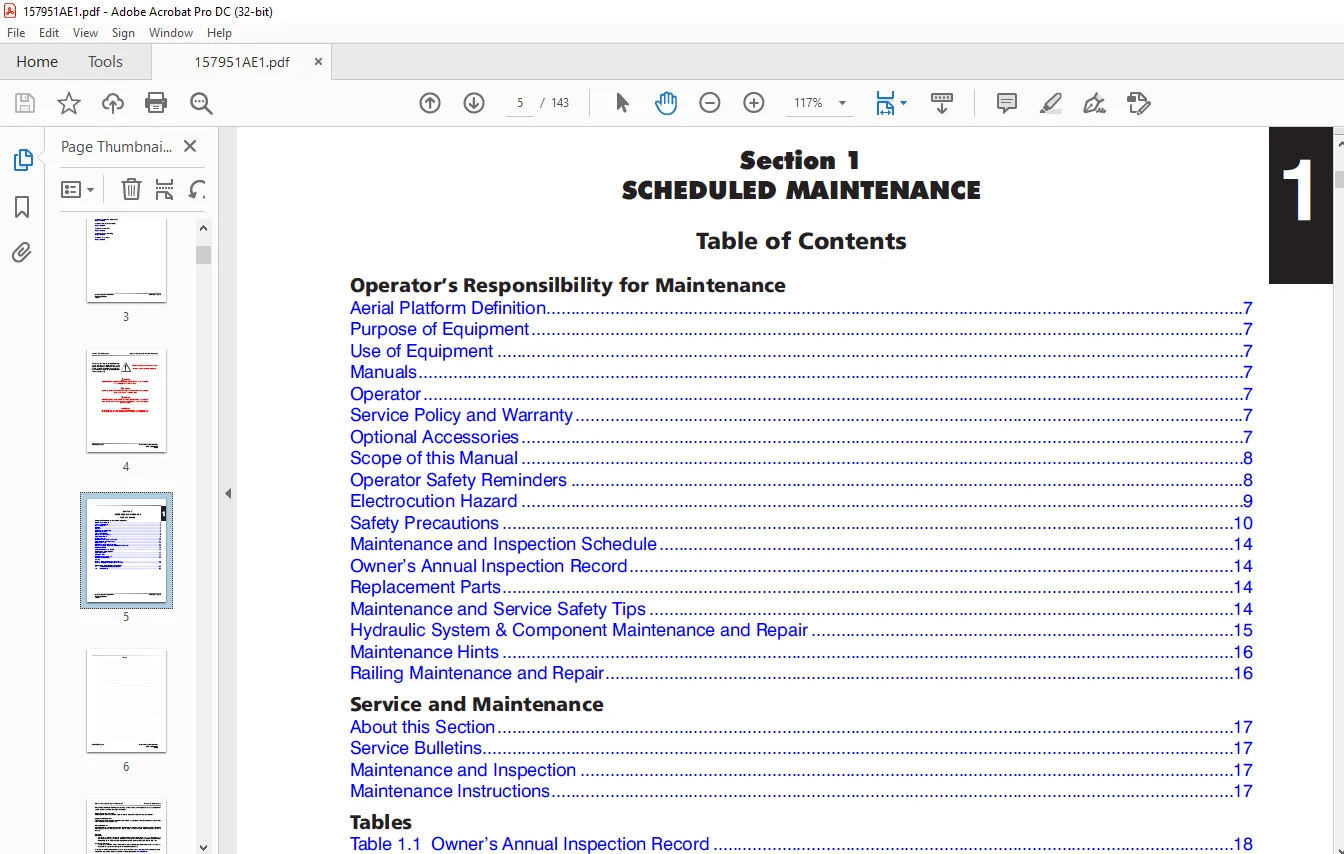
TABLE OF CONTENTS:
Skyjack SJ6826 RT SJ6832 RT Rough Terrain Scissors Service Manual 157951AE – PDF DOWNLOAD
Table of Contents...........................................................................................................................................  3
Section 1 - Scheduled Maintenance...........................................................................................................................  5
	Operator’s Responsilbility for Maintenance..............................................................................................................  7
		Aerial Platform Definition..........................................................................................................................  7
		Purpose of Equipment................................................................................................................................  7
		Use of Equipment....................................................................................................................................  7
		Manuals.............................................................................................................................................  7
		Operator............................................................................................................................................  7
		Service Policy and Warranty.........................................................................................................................  7
		Optional Accessories................................................................................................................................  7
		Scope of this Manual................................................................................................................................  8
		Operator Safety Reminders...........................................................................................................................  8
		Electrocution Hazard................................................................................................................................  9
		Safety Precautions.................................................................................................................................. 10
		Maintenance and Inspection Schedule................................................................................................................. 14
		Owner’s Annual Inspection Record.................................................................................................................... 14
		Replacement Parts................................................................................................................................... 14
		Maintenance and Service Safety Tips................................................................................................................. 14
		Hydraulic System & Component Maintenance and Repair................................................................................................. 15
		Maintenance Hints................................................................................................................................... 16
		Railing Maintenance and Repair...................................................................................................................... 16
	Service and Maintenance................................................................................................................................. 17
		About this Section.................................................................................................................................. 17
		Service Bulletins................................................................................................................................... 17
		Maintenance and Inspection.......................................................................................................................... 17
		Maintenance Instructions............................................................................................................................ 17
	Tables.................................................................................................................................................. 18
		Table 1.1  Owner’s Annual Inspection Record......................................................................................................... 18
		Table 1.2  Maintenance and Inspection Checklist..................................................................................................... 19
	Service and Maintenance Inspections..................................................................................................................... 20
		1.1 Scheduled Maintenance Inspections............................................................................................................... 20
		1.2 Function Tests.................................................................................................................................. 32
Section 2 - Maintenance Tables and Diagrams................................................................................................................. 41
	Tables.................................................................................................................................................. 42
		Table 2.1  Specifications and Features.............................................................................................................. 42
		Table 2.2  Floor Loading Pressure................................................................................................................... 44
		Table 2.3  Maximum Platform Capacities (Evenly Distributed)......................................................................................... 45
		Table 2.4  Fluids Table............................................................................................................................. 46
		Table 2.5  Torque Specifications.................................................................................................................... 47
		Table 2.6  Torque Specifications for Fasteners (Imperial)........................................................................................... 48
		Table 2.7  Torque Specifications for Fasteners (Metric)............................................................................................. 49
		Table 2.8  Torque Specifications for Hydraulic Couplings & Hoses.................................................................................... 50
Section 3 - System Component Identification and Schematics.................................................................................................. 51
	Charts.................................................................................................................................................. 52
		3.1.  Hydraulic Symbol Chart........................................................................................................................ 52
		3.2.  Electrical Symbol Chart....................................................................................................................... 53
		3.3.  Hydraulic Schematic Parts List................................................................................................................ 54
	Parts List.............................................................................................................................................. 54
		3.4.  Electrical Parts List ........................................................................................................................ 56
	Diagrams and Schematics................................................................................................................................. 61
		3.5.  Hydraulic Schematic........................................................................................................................... 61
		3.6.  Hydraulic Manifolds And Ports Identification.................................................................................................. 62
		3.7.  Control Box with Rotary Switches Wiring Diagram............................................................................................... 64
		3.8.  Control Box with Toggle Switches Wiring Diagram............................................................................................... 65
		3.9.  Outrigger/Hydraulic Generator Control Console Wiring Diagram.................................................................................. 66
		3.10.  Scissor Arm Control Cable Wiring Diagram..................................................................................................... 67
		3.11.  Main Manifold Harness Wiring Diagram......................................................................................................... 68
		3.12.  Kubota Engine Wiring Diagram (Dual Fuel System).............................................................................................. 69
		3.13.  Kubota Engine Wiring Diagram (Diesel Fuel System)............................................................................................ 70
		3.14.  Outrigger Harness Wiring Diagram............................................................................................................. 71
		3.15.  Hydraulic Generator Electrical Panel Assembly................................................................................................ 72
		3.16.  Electrical Panel Wiring Diagram.............................................................................................................. 73
		3.17.  Electrical Schematic (No Option with Kubota Dual Fuel Engine and Rotary Switch Control Box).................................................. 74
		3.18.  Electrical Schematic (All  Option with Kubota Dual Fuel Engine and Rotary Switch Control Box)................................................ 75
		3.19.  Electrical Schematic (All Option with Kubota Diesel Engine and Rotary Switch Control Box).................................................... 76
		3.20.  Electrical Schematic (No Option with Kubota Dual Fuel Engine and Toggle Switch Control Box).................................................. 77
		3.21.  Electrical Schematic (All  Option with Kubota Dual Fuel Engine and Toggle Switch Control Box)................................................ 78
		3.22.  Electrical Schematic (All Option with Kubota Diesel Engine and Toggle Switch Control Box).................................................... 79
		Introduction........................................................................................................................................ 82
Section 4 - Troubleshooting Information..................................................................................................................... 80
	Electrical System....................................................................................................................................... 83
		4.1-1 All Controls Inoperative...................................................................................................................... 83
		4.1-2 No Power To Platform.......................................................................................................................... 83
		4.1-3 All Functions Inoperative from The Platform................................................................................................... 84
		4.1-4 Engine Will Not Crank from Platform or Base Control Console................................................................................... 84
		4.1-5 Engine Cranks But Will Not Start - Kubota Diesel.............................................................................................. 85
		4.1-6 Engine Cranks But Will Not Start - Kubota Dual Fuel........................................................................................... 85
		4.1-7 Glow Plugs Inoperative from Engine Controls or Platform (Diesel Models)....................................................................... 86
		4.1-8 Choke Inoperative from Engine Controls or Platform (Kubota Dual Fuel)......................................................................... 86
		4.1-9 High Throttle Inoperative..................................................................................................................... 87
		4.1-10 High Throttle On Demand Inoperative (Kubota Dual Fuel)....................................................................................... 88
		4.1-11 Drive and Steer Inoperative (Machines without outriggers option)............................................................................. 88
		4.1-12 Drive and Steer Inoperative (Machines with outriggers option)................................................................................ 89
		4.1-13 Brakes Will Not Release...................................................................................................................... 90
		4.1-14 Steer Right Inoperative...................................................................................................................... 90
		4.1-15 Steer Left Inoperative....................................................................................................................... 90
		4.1-16 Reverse Drive Inoperative.................................................................................................................... 90
		4.1-17 Forward Drive Inoperative.................................................................................................................... 91
		4.1-18 First Drive Speed and Steering Inoperative................................................................................................... 92
		4.1-19 Second Drive Speed Inoperative............................................................................................................... 92
		4.1-20 Third Drive Speed Inoperative................................................................................................................ 93
		4.1-22 High Drive Speed Inoperative................................................................................................................. 94
		4.1-21 Up Circuit Inoperative from Platform......................................................................................................... 94
		4.1-22 Up Circuit Inoperative from Base Control Console............................................................................................. 94
		4.1-23 Up Circuit Inoperative from Platform or Base Control Console (without Outriggers)............................................................ 95
		4.1-24 Platform will Not Lift from Platform or Base Control Console with Outriggers Retracted (Lift Operates Correctly with Outriggers Extended).... 95
		4.1-25 Platform will Not Lift from Platform or Base Control Console with Outriggers Extended........................................................ 96
		4.1-26 Platform will Not Lift from Platform or Base Control Console with Outriggers Extended or Retracted........................................... 97
		4.1-27 Down Circuit Inoperative from Platform....................................................................................................... 97
		4.1-28 Down Circuit Inoperative from Base........................................................................................................... 97
		4.1-29 Hydraulic Generator Inoperative.............................................................................................................. 98
		4.1-30 Hydraulic Generator will not Shut Off from Generator Switch.................................................................................. 99
		4.1-31 All Outriggers Inoperative (Auto-Level and Manual)........................................................................................... 99
		4.1-32 All Outriggers Inoperative  (Auto-Level and Manual from Platform Controls)...................................................................100
		4.1-33 All Outriggers Inoperative (Base Controls only)..............................................................................................100
		4.1-34 All Outriggers Inoperative (Auto Level only).................................................................................................100
		4.1-35 All Outriggers Inoperative (Auto Level only).................................................................................................101
		4.1-36 Left Front Outrigger Inoperative Manually....................................................................................................102
		4.1-37 Right Front Outrigger Inoperative Manually...................................................................................................102
		4.1-38 Right Rear Outriggers Inoperative Manually...................................................................................................102
		4.1-39 Left Rear Outriggers Inoperative Manually....................................................................................................102
		4.1-40 Individual Outrigger Functions Inoperative (Auto-Level) .....................................................................................103
		4.1-41 Auto-Level Inoperative.......................................................................................................................103
		4.1-42 Auto All Up Inoperative (Retract)............................................................................................................103
	Hydraulic System........................................................................................................................................104
		4.2-1 All Functions Inoperative ....................................................................................................................104
		4.2-2 Steering Inoperative..........................................................................................................................104
		4.2-3 Lift, Steer and First Drive Speed Inoperative.................................................................................................104
		4.2-4 Second Drive Speed Inoperative................................................................................................................104
		4.2-5 Drive Inoperative.............................................................................................................................104
		4.2-6 Drive Sluggish................................................................................................................................105
		4.2-7 Reverse Drive Inoperative.....................................................................................................................105
		4.2-8 Forward Drive Inoperative.....................................................................................................................105
		4.2-9 Drive Inoperative When in Low Drive...........................................................................................................105
		4.2-10 Drive Inoperative When in High Drive.........................................................................................................105
		4.2-11 Brakes Will Not Release......................................................................................................................105
		4.2-12 Up Circuit Inoperative.......................................................................................................................105
		4.2-13 Down Circuit Inoperative.....................................................................................................................106
		4.2-14 Hydraulic Generator Inoperative..............................................................................................................106
		4.2-15 All Outriggers Inoperative...................................................................................................................106
		4.2-16 Left Front Outriggers Inoperative............................................................................................................106
		4.2-17 Right Front Outriggers Inoperative...........................................................................................................106
		4.2-18 Right Rear Outriggers Inoperative............................................................................................................106
		4.2-19 Left Rear Outriggers Inoperative.............................................................................................................107
		4.2-20 Outriggers Drift In..........................................................................................................................107
		General ............................................................................................................................................109
		Safety and Workmanship..............................................................................................................................109
Section 5 - Procedures......................................................................................................................................108
	Base....................................................................................................................................................109
		5.1-1 Winching and Towing Procedures and Parking Brake System ......................................................................................109
		5.1-2 Wheel Bolt/Nut Inspection and Torquing Procedure..............................................................................................110
		5.1-3 Wheel Reinstallation and Torquing Procedure...................................................................................................111
		5.1-4 Reconnecting the Platform Control Box for Use from the Ground ................................................................................112
		5.1-5 Tightening and Torque Recommendations for Hydraulic Couplings and Hoses ......................................................................113
		5.1-6 Checking the Holding Valve....................................................................................................................114
		5.1-7 System Pressure Setting.......................................................................................................................115
		5.1-8 Lift Pressure Setting.........................................................................................................................116
		5.1-9 Grease Points.................................................................................................................................117
	Engine..................................................................................................................................................118
		5.2-1 Kubota Dual Fuel (DF972) Resistance Checks....................................................................................................118
		5.2-2 Fan Belt Replacement and Adjustment...........................................................................................................119
		5.2-3  Kubota Dual Fuel (DF972) Engine Throttle Setting.............................................................................................120
		5.2-4  Kubota Diesel (D902) Engine Throttle Setting.................................................................................................122
		5.2-5 Replacing the Air Cleaner Element.............................................................................................................123
		5.2-6 Replacing the Fuel Filter Element (Kubota D902)...............................................................................................124
		5.2-7 Bleeding the Fuel System of Air (Kubota D902).................................................................................................124
		5.2-8 Replacing the Oil Filter Cartridge............................................................................................................125
		5.2-9 Changing the Oil..............................................................................................................................125
		5.2-10 Checking and Replenishing the Radiator Coolant Level.........................................................................................126
		5.2-11 Draining and Refilling the Radiator..........................................................................................................126
	Outriggers..............................................................................................................................................127
		5.3-1 Auto-Leveling Outrigger PC Board Layout.......................................................................................................127
		5.3-2 Outrigger Mechanical Limit Switch Wiring Diagram..............................................................................................128
		5.3-3 Auto-Leveling Outrigger Settings and Error Codes..............................................................................................129
		5.3-4 Auto-Leveling Outrigger Error Code Breakdown..................................................................................................130
		5.3-5 Hand Held Calibration/Diagnostic Tool Key Functions...........................................................................................131
		5.3-6 Outrigger Control Module Instructions.........................................................................................................132
		5.3-7 Auto-Leveling Outrigger Control Module Pin Reference Chart....................................................................................135
		5.3-8 Outrigger Upper Limit Switch (LS61, LS62, LS63, LS64) Replacement and Adjustment..............................................................136
		5.3-9 Outrigger Lower Limit Switch (LS65, LS66, LS67, LS68) Replacement and Adjustment..............................................................137
	Scissors................................................................................................................................................139
		5.4-1 High Speed Cutout Limit Switch (LS5) Replacement and Adjustment...............................................................................139
	Platform................................................................................................................................................141
		5.5-1 Gate Springe Hinge Adjustment.................................................................................................................141
IMAGES PREVIEW OF THE MANUAL:
Need help? Contact: [email protected]
PLEASE NOTE:
- This is not a physical manual but a digital manual – meaning no physical copy will be couriered to you. The manual can be yours in the next 2 mins as once you make the payment, you will be directed to the download page IMMEDIATELY.
- This is the same manual used by the dealers inorder to diagnose your vehicle of its faults.
- Require some other service manual or have any queries: please WRITE to us at [email protected]
S.V