★ TRUSTED BY 321,897+ PROFESSIONALS WORLDWIDE
🏒
Trusted Business
Verified & Licensed
πŸ›‘οΈ
Virus Free Files
100% Safe Downloads
πŸ”’
Secure Payment
SSL Protected
⚑
Instant Delivery
Available Immediately
Sale!

Skyjack SJ6826 RT & SJ6832 RT Rough Terrain Scissors Service Manual – 213560AEA

Original price was: $39.95.Current price is: $22.95.

Complete service manual for Skyjack SJ6826 RT and SJ6832 RT rough terrain scissor lifts. Covers maintenance, hydraulic and electrical schematics, troubleshooting, engine procedures, and more. Instant PDF download.

SKU: SKYJ-SJ6826RT-SJ6832RT-SM-213560AEA-HD Category: Tags: , , , Vendor: Motor Pool Manuals
⚑
Instant PDF Download
Available immediately
πŸ’Ύ
Save to Your Device
Download & keep forever
πŸ›‘οΈ
Antivirus Scanned
100% virus-free
🌍
Trusted Worldwide
175,000+ customers

Description

File Details

  • Manual Type: Service Manual
  • Brand: Skyjack
  • Models: SJ6826 RT, SJ6832 RT
  • Document Number: 213560AEA
  • Language: English
  • Page Count: 212 pages
  • File Format: PDF

Chapters Covered

  • Section 1 β€” Maintenance: Read and heed, general information, owner’s annual inspection record, replacement parts, maintenance and service safety tips, hydraulic system and component maintenance, hydraulic oil maintenance, railing maintenance, multi-conductor control cable repair, scheduled maintenance and inspections, service bulletins, maintenance and inspection schedules, pre-delivery/maintenance inspection checklist, inspection points, function tests.
  • Section 2 β€” Maintenance Tables and Diagrams: Standard hose numbering system, torque specifications for metric fasteners, US imperial fasteners, hydraulic couplings and hoses, MEWP torque specifications, specifications and features, fluids, maximum platform capacities.
  • Section 3 β€” System Component Identification and Schematics: Electrical symbol chart, hydraulic symbol chart, wire number and colour chart, hydraulic parts list, electrical parts list, major component identification, main manifold identification, splitter and outrigger manifolds, control box wiring diagram, base-to-platform control cable, beeper and angle transducer harnesses, main manifold valve harness, telematics harnesses, engine harnesses for Kubota diesel and dual fuel, outrigger control boxes, hydraulic generator panel, electrical panel diagrams for ANSI/CSA, CE, AS, KC, positive air shut-off and soft stop, hydraulic schematics, and electrical schematics for Kubota dual fuel WG752 and Kubota diesel D902 across multiple control module configurations.
  • Section 4 β€” Troubleshooting Information: Electrical system troubleshooting, all controls inoperative, no power to platform, base and platform function failures, engine crank and start issues for Kubota diesel and dual fuel, glow plugs, high throttle, drive and steer faults, brake release, up and down circuit faults, hydraulic generator, outrigger faults, hydraulic system troubleshooting, load sense system codes.
  • Section 5 β€” Procedures: General safety and workmanship, platform gate spring hinge adjustment, platform mounting hardware, scissors high speed cutout limit switch replacement and testing, Kubota dual fuel and diesel engine resistance checks and throttle settings, fuel filter, air bleed, fan belt, air cleaner, oil filter, oil change, radiator coolant, wheel bolt torque, wheel installation, wheel nut tightening, grease points, tilt switch setup and programming, hydraulic coupling torque, holding valve checks, system pressure, lift pressure, drive circuit operation and flushing, drive motor tests, outrigger limit switch wiring and replacement, control module identification and locations, controller LED error codes and actions, GP-108, GP-106 and GP-102 control modules, EZcal diagnostic tool, outrigger PC board layout.

This Skyjack SJ6826 RT and SJ6832 RT rough terrain scissors service manual gives technicians and owners a complete reference for maintaining, diagnosing and repairing these mobile elevating work platforms. Across its 212 pages, the document combines scheduled maintenance checklists, detailed hydraulic and electrical schematics, fault-code tables, and step-by-step repair procedures for the major systems. The troubleshooting section helps isolate electrical and hydraulic problems quickly, while the procedures section walks through component replacement, calibration, pressure setting and engine service. Whether you are performing an annual inspection, chasing a drive fault, setting lift pressure, or replacing an outrigger limit switch, the manual provides the specifications and sequences needed to work accurately.

What This Manual Enables

With this service manual, you can confidently carry out preventive maintenance, diagnose hydraulic and electrical faults, adjust engine throttle settings, test drive circuits, calibrate load-sense and outrigger control modules, and replace worn components. It covers the Kubota D902 diesel and Kubota WG752 dual fuel engines, along with the GP-102, GP-106 and GP-108 control modules used across these machines. The electrical schematics cover multiple regional configurations including ANSI/CSA, CE, AS and KC, so you can match the diagram to the machine’s market specification.

Why It Matters

Rough terrain scissor lifts operate in demanding environments where incorrect repair procedures or missed maintenance can lead to downtime, component damage, or unsafe operation. Using the factory-documented torque values, pressure settings, limit switch adjustments and calibration routines in this manual helps ensure the equipment performs as designed. The troubleshooting tables reduce guesswork by linking probable causes to specific remedies, which is especially valuable when dealing with intermittent electrical faults or hydraulic drift.

Complete PDF Bookmark Tree

Complete Bookmarks

The complete bookmarks in the β€œSkyjack SJ6826 RT & SJ6832 RT Rough Terrain Scissors Service Manual – 213560AEA” are as follows:

Section 1 – Maintenancep. 11
1.1 Read and heedp. 11
1.1-1 Mobile Elevating Work Platform (MEWP) definitionp. 11
1.1-2 Purpose of equipmentp. 11
1.1-3 Use of equipmentp. 11
1.1-4 Service Policy and Warrantyp. 11
1.1-5 Ownership of MEWPp. 11
1.1-6 Optional equipmentp. 11
1.2 General Informationp. 12
1.2-1 Owner’s annual inspection recordp. 12
1.2-2 Replacement partsp. 12
1.2-3 Maintenance and service safety tipsp. 12
1.2-4 Hydraulic system & component maintenance and repairp. 13
1.2-5 Hydraulic oil maintenancep. 13
1.2-6 Hydraulic maintenance tipsp. 13
1.2-7 Railing maintenance and repairp. 14
1.2-8 Multi-conduction control cable repairp. 14
1.3 Scheduled maintenance and inspectionsp. 14
1.3-1 Service bulletinsp. 14
1.3-2 Maintenance and inspectionsp. 14
1.3-3 Schedule and instructionsp. 15
1.3-4 Repairsp. 15
1.3-5 Pre-delivery/maintenance inspection checklistp. 16
1.3-6 Inspection pointsp. 17
1.3-7 Function testsp. 26
Section 2 – Maintenance Tables and Diagramsp. 27
2.1 Standard hose numbering systemp. 27
2.2 Torque specifications for fasteners (metric)p. 29
2.3 Torque specifications for fasteners (US imperial)p. 30
2.4 Torque specifications for hydraulic couplings & hosesp. 31
2.5 MEWP torque specificationsp. 32
2.6 Specifications and featuresp. 33
2.7 Fluidsp. 34
2.8 Maximum platform capacities (evenly distributed)p. 34
Section 3 – System Component Identification and Schematicsp. 35
3.1 Electrical Symbol Chartp. 36
3.2 Hydraulic Symbol Chartp. 37
3.3 Wire Number and Colour Chartp. 38
3.4 Hydraulic Parts Listp. 39
3.5 Electrical Parts Listp. 41
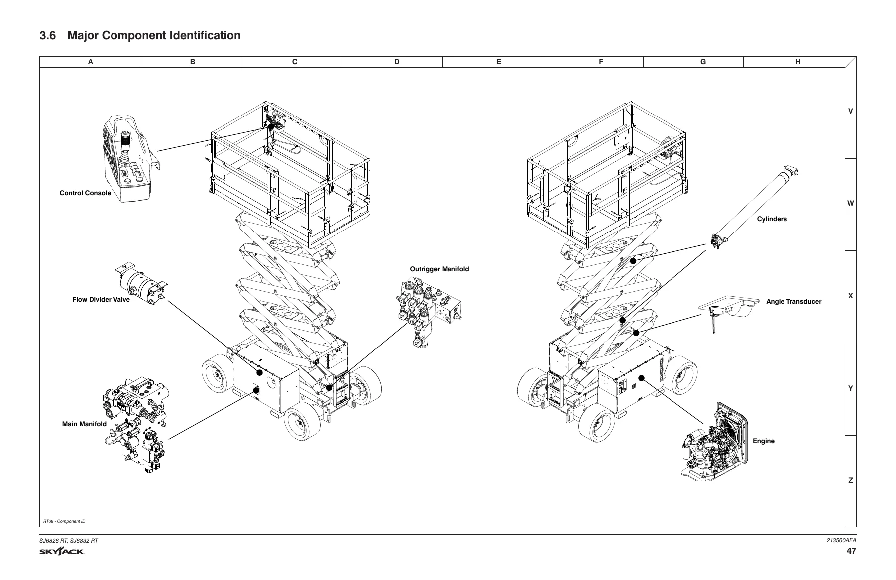
3.6 Major Component Identificationp. 47
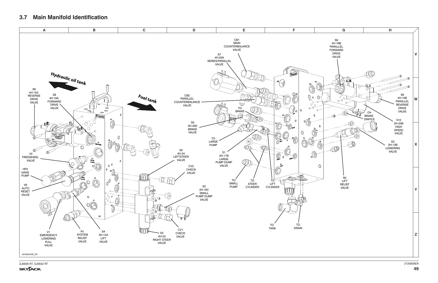
3.7 Main Manifold Identificationp. 49
3.8 Splitter and Outrigger Manifolds Identificationp. 50
3.9 Control Box Wiring Diagramp. 51
3.10 Base to Platform Control Cablep. 52
3.11 Beeper and Angle Transducer Harnessesp. 53
3.12 Main Manifold Valve Harness Wiring Diagramp. 54
3.13 Elevate Telematics Harnessp. 55
3.14 Kubota Engine Harness – Dieselp. 56
3.15 Kubota Engine Harness – Dual Fuelp. 57
3.16 Outrigger Control Boxp. 58
3.17 Outrigger/Hydraulic Generator Control Boxp. 59
3.18 Hydraulic Generator Electrical Panel Assemblyp. 60
3.19 ZTR Telematics Harness Wiring Diagramp. 61
3.20 Incandescent Flashing Light Relay Harnessp. 62
3.21 Pressure Transducer Harnessp. 63
3.22 Outrigger Electrical Assemblyp. 65
3.23 Outrigger/Hydraulic Generator Electrical Assemblyp. 66
3.24 Electrical Panel Diagram – ANSI/CSA, CE & ASp. 67
3.25 Electrical Panel Diagram – KCp. 68
3.26 Electrical Panel Diagram – Positive Air Shut-Offp. 69
3.27 Electrical Panel Diagram – Soft Stopp. 70
3.28 Hydraulic Schematic – ANSI/CSAp. 71
3.29 Hydraulic Schematic – CE/ASp. 72
3.30 Hydraulic Schematic – KCp. 73
3.31 Electrical Schematic – Kubota Dual Fuel WG752 (GP-108) – ANSI/CSAp. 74
3.32 Electrical Schematic – Kubota Dual Fuel WG752 (GP-102 & GP-106) – ANSI/CSAp. 75
3.33 Electrical Schematic – Kubota Dual Fuel WG752 (GP-108) – ANSI/CSA – No Optionsp. 76
3.34 Electrical Schematic – Kubota Dual Fuel WG752 (GP-102) – ANSI/CSA – No Optionsp. 77
3.35 Electrical Schematic – Kubota Diesel D902 (GP-108) – ANSI/CSAp. 78
3.36 Electrical Schematic – Kubota Diesel D902 (GP-102 & GP-106) – ANSI/CSAp. 79
3.37 Electrical Schematic – Kubota Diesel D902 (GP-108) – ANSI/CSA – No Optionsp. 80
3.38 Electrical Schematic – Kubota Diesel D902 (GP-102) – ANSI/CSA – No Optionsp. 81
3.39 Electrical Schematic – Kubota Diesel D902 (GP-108) – CEp. 82
3.40 Electrical Schematic – Kubota Diesel D902 (GP-102 & GP-106) – CEp. 83
3.41 Electrical Schematic – Kubota Diesel D902 (GP-108) – ASp. 84
3.42 Electrical Schematic – Kubota Diesel D902 (GP-102 & GP-106) – ASp. 85
3.43 Electrical Schematic – Kubota Diesel D902 (GP-108) – CE/AS – No Optionsp. 86
3.44 Electrical Schematic – Kubota Diesel D902 (GP-102) – CE/AS – No Optionsp. 87
3.45 Electrical Schematic – (GP-108) – KCp. 88
Section 4 – Troubleshooting Informationp. 91
4.1 Introductionp. 91
4.2 Electrical Systemp. 92
4.2-1 All Controls Inoperativep. 92
4.2-2 No Power to Platformp. 93
4.2-3 All Functions Inoperative from The Basep. 93
4.2-4 All Functions Inoperative from Platformp. 95
4.2-5 Engine Does not Crank from Platform nor Base Control Consolep. 97
4.2-6 Engine Cranks but Does not Start – Kubota Dieselp. 99
4.2-7 Engine Cranks but Does not Start – Kubota Dual Fuel (Propane/ Gas)p. 100
4.2-8 Glow Plugs Inoperative from neither Engine Controls nor Platform (Diesel Models)p. 101
4.2-9 High Throttle Inoperativep. 102
4.2-10 Drive and Steer Inoperative (Machines without outriggers option)p. 103
4.2-11 Brakes Do not Releasep. 106
4.2-12 Steer Right Inoperativep. 106
4.2-13 Steer Left Inoperativep. 107
4.2-14 Reverse Drive Inoperativep. 107
4.2-15 Forward Drive Inoperativep. 108
4.2-16 First Drive Speed and Steering Inoperativep. 109
4.2-17 Second Drive Speed Inoperativep. 110
4.2-18 Third Drive Speed Inoperativep. 112
4.2-19 High Torque/Parallel Drive Inoperativep. 112
4.2-20 Up Circuit Inoperative from Platformp. 114
4.2-21 Up Circuit Inoperative from Base Control Consolep. 114
4.2-22 Up Circuit Inoperative from Platform or Base Control Console (without Outriggers)p. 114
4.2-23 Platform does not Lift from Platform or Base Control Console with Outriggers Retracted (Lift Operates Correctly with Outriggers Extended)p. 115
4.2-24 Platform does not Lift from Platform or Base Control Console with Outriggers Extendedp. 116
4.2-25 Platform does not Lift from Platform or Base Control Console with Outriggers Extended or Retractedp. 118
4.2-26 Down Function Inoperative from Platformp. 118
4.2-27 Down Function Inoperative from Basep. 119
4.2-28 Hydraulic Generator Inoperativep. 120
4.2-29 Hydraulic Generator does not Shut Off from Generator Switchp. 122
4.2-30 All Outriggers Inoperative (Auto-Level and Manual)p. 122
4.2-31 All Outriggers Inoperative (Auto-Level and Manual from Platform Controls)p. 123
4.2-32 All Outriggers Inoperative (Base Controls only)p. 124
4.2-33 All Outriggers Inoperative (Auto Level only)p. 124
4.2-34 All Outriggers Inoperative (Auto Level only)p. 125
4.2-35 Right Front Outrigger Inoperative Manuallyp. 126
4.2-36 Right Rear Outriggers Inoperative Manuallyp. 127
4.2-37 Left Rear Outriggers Inoperative Manuallyp. 128
4.2-38 Individual Outrigger Functions Inoperative (Auto-Level)p. 129
4.2-39 Auto-Level Inoperativep. 130
4.2-40 Auto All Up Inoperative (Retract)p. 130
4.3 Hydraulic Systemsp. 131
4.3-1 All Functions Inoperativep. 132
4.3-2 Steering Inoperativep. 132
4.3-3 Lift, Steer and First Drive Speed Inoperativep. 132
4.3-4 Second Drive Speed Inoperativep. 132
4.3-5 Drive Inoperativep. 132
4.3-6 Drive Sluggishp. 133
4.3-7 Reverse Drive Inoperativep. 133
4.3-8 Forward Drive Inoperativep. 133
4.3-9 Drive Inoperative When in Low Drivep. 133
4.3-10 Drive Inoperative When in High Drivep. 133
4.3-11 Brakes Do Not Releasep. 134
4.3-12 Up Circuit Inoperativep. 134
4.3-13 Down Circuit Inoperativep. 134
4.3-14 Hydraulic Generator Inoperativep. 134
4.3-15 All Outriggers Inoperativep. 135
4.3-16 Outriggers Inoperativep. 135
4.3-17 Outriggers Drift Inp. 136
4.3-18 Load Sense System Codesp. 136
Section 5 – Proceduresp. 141
5.1 Generalp. 141
5.1-1 Safety and workmanshipp. 141
5.2 Platformp. 142
5.2-1 Adjust the gate spring hingep. 142
5.2-2 Platform mounting hardwarep. 142
5.3 Scissorsp. 143
5.3-1 Replace and adjust the high speed cutout limit switch (LS5)p. 143
5.3-2 Test the high speed cutout limit switchp. 144
5.4 Enginep. 145
5.4-1 Kubota dual fuel WG752 resistance checksp. 145
5.4-2 Kubota dual fuel WG752 engine throttle settingp. 146
5.4-3 Kubota diesel D902 engine throttle settingp. 147
5.4-4 Replace the fuel filter element – Kubota D902p. 149
5.4-5 Bleed the fuel system of air – Kubota D902p. 149
5.4-6 Fan belt replacement and adjustmentp. 150
5.4-7 Replace the air cleaner elementp. 151
5.4-8 Replace the oil filter cartridgep. 151
5.4-9 Change the oilp. 152
5.4-10 Check and replenishing the radiator coolant levelp. 152
5.4-11 Drain and refill the radiatorp. 153
5.5 Basep. 154
5.5-1 Inspect and torque the wheel bolts in sequencep. 154
5.5-2 Install and torque the wheelsp. 154
5.5-3 Tighten the wheel nutp. 155
5.5-4 Grease pointsp. 156
5.5-5 Set Up a New Tilt Switch – KC onlyp. 157
5.5-6 Reprogram an Existing Tilt Switch – KC onlyp. 158
5.5-7 Tilt switch Operation – KC onlyp. 159
5.6 Hydraulicsp. 160
5.6-1 Tightening and torque recommendations for hydraulic couplings and hosesp. 160
5.6-2 Do a check of the holding valvep. 161
5.6-3 Set the system pressurep. 162
5.6-4 Set the lift pressurep. 163
5.6-5 Drive circuit operationp. 164
5.6-6 Flush the drive circuitp. 166
5.6-7 Drive motor testp. 167
5.6-8 System pressure testp. 167
5.6-9 Drive pressure testp. 167
5.7 Outriggersp. 168
5.7-1 Outrigger mechanical limit switch wiring diagramp. 168
5.7-2 Outrigger upper limit switch (LS61, LS62, LS63, LS64) replacement and adjustmentp. 169
5.7-3 Outrigger lower limit switch (LS65, LS66, LS67, LS68) replacement and adjustmentp. 170
5.8 Control Modules Identification and Locationsp. 171
5.8-2 Locationsp. 171
5.8-1 Identificationp. 172
5.9 Controller LED Error Codesp. 173
5.10 Controller LED Error Code Actionsp. 175
5.10-1 GP-108 LED error codesp. 175
5.10-2 GP-106 Auto-levelling outrigger settings and error codesp. 177
5.10-3 GP-102 LED Error codesp. 179
5.11 GP-108 Control Modulep. 181
5.11-1 Identificationp. 181
5.11-2 GP-108 Overload/Outrigger controller pin reference tablep. 186
5.12 GP-106 (OCM1) Control Modulep. 188
5.12-1 GP106 Identificationp. 188
5.12-2 Outrigger control module (GP-106/OCM1) instructionsp. 188
5.12-3 Set up the GP-106 outrigger controllerp. 192
5.12-4 GP-106 outrigger controller pin reference tablep. 193
5.13 GP-102 (CM1) Control Modulep. 195
5.13-1 GP102 Identificationp. 195
5.13-2 Initial setup and change defaultsp. 195
5.13-3 Set up the GP-102 load sense controllerp. 196
5.13-4 GP-102 Load sense controller pin reference tablep. 198
5.13-5 Control module load calibration – code messages and definitionsp. 200
5.14 EZcal Diagnostic Toolp. 205
5.14-1 Hand held EZcal calibration and diagnostic tool key functionsp. 205
5.14-2 EZcal pro updatep. 206
5.14-3 Flash the controllerp. 208
5.15 Outrigger PC board layoutp. 209
5.15-1 Access levelsp. 210
5.15-2 Outrigger codesp. 210
5.15-3 Curve/group codesp. 210


IMAGES PREVIEW

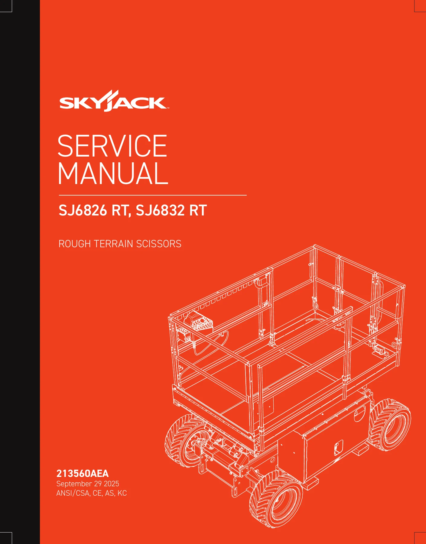
Skyjack SJ6826 RT & SJ6832 RT Rough Terrain Scissors Service Manual - 213560AEA β€” PDF page 1 preview
Skyjack SJ6826 RT & SJ6832 RT Rough Terrain Scissors Service Manual - 213560AEA β€” PDF page 47 preview
Skyjack SJ6826 RT & SJ6832 RT Rough Terrain Scissors Service Manual - 213560AEA β€” PDF page 49 preview

Instant PDF Delivery

This Skyjack SJ6826 RT and SJ6832 RT service manual is delivered as an instant PDF download after purchase. There is no shipping, no waiting for a physical book, and no restrictions on printing. You can view it on a laptop, tablet or smartphone, print the pages you need for the workshop, and keep the complete document on hand for every service job. The searchable text and clear page layout make it easy to jump to the section you need, whether you are working in the field or in the shop.

Reviews

There are no reviews yet.

Be the first to review “Skyjack SJ6826 RT & SJ6832 RT Rough Terrain Scissors Service Manual – 213560AEA”

What Our Customers Say

β˜…β˜…β˜…β˜…β˜… Live reviews from customers
Loading customer reviews...
0
    0
    Your Cart
    Your cart is emptyReturn to Shop
    πŸ›’
    Recently Purchased
    πŸ•’ verified order