Trusted Business
Verified & Licensed
Virus Free Files
100% Safe Downloads
Secure Payment
SSL Protected
Instant Delivery
Available Immediately
Skyjack SJ85 AJ Articulating Boom Service Manual 210341AF – PDF DOWNLOAD
$28.95
Skyjack SJ85 AJ Articulating Boom Service Manual 210341AF – PDF DOWNLOAD
SJ85AJ: 95400001 to 95499999
Instant PDF Download
Available immediately
Save to Your Device
Download & keep forever
Antivirus Scanned
100% virus-free
Trusted Worldwide
175,000+ customers
Description
Skyjack SJ85 AJ Articulating Boom Service Manual 210341AF – PDF DOWNLOAD
FILE DETAILS:
Skyjack SJ85 AJ Articulating Boom Service Manual 210341AF – PDF DOWNLOAD
Language : English
Pages : 204
Downloadable : Yes
File Type : PDF
DESCRIPTION:
Skyjack SJ85 AJ Articulating Boom Service Manual 210341AF – PDF DOWNLOAD
SJ85AJ: 95400001 to 95499999
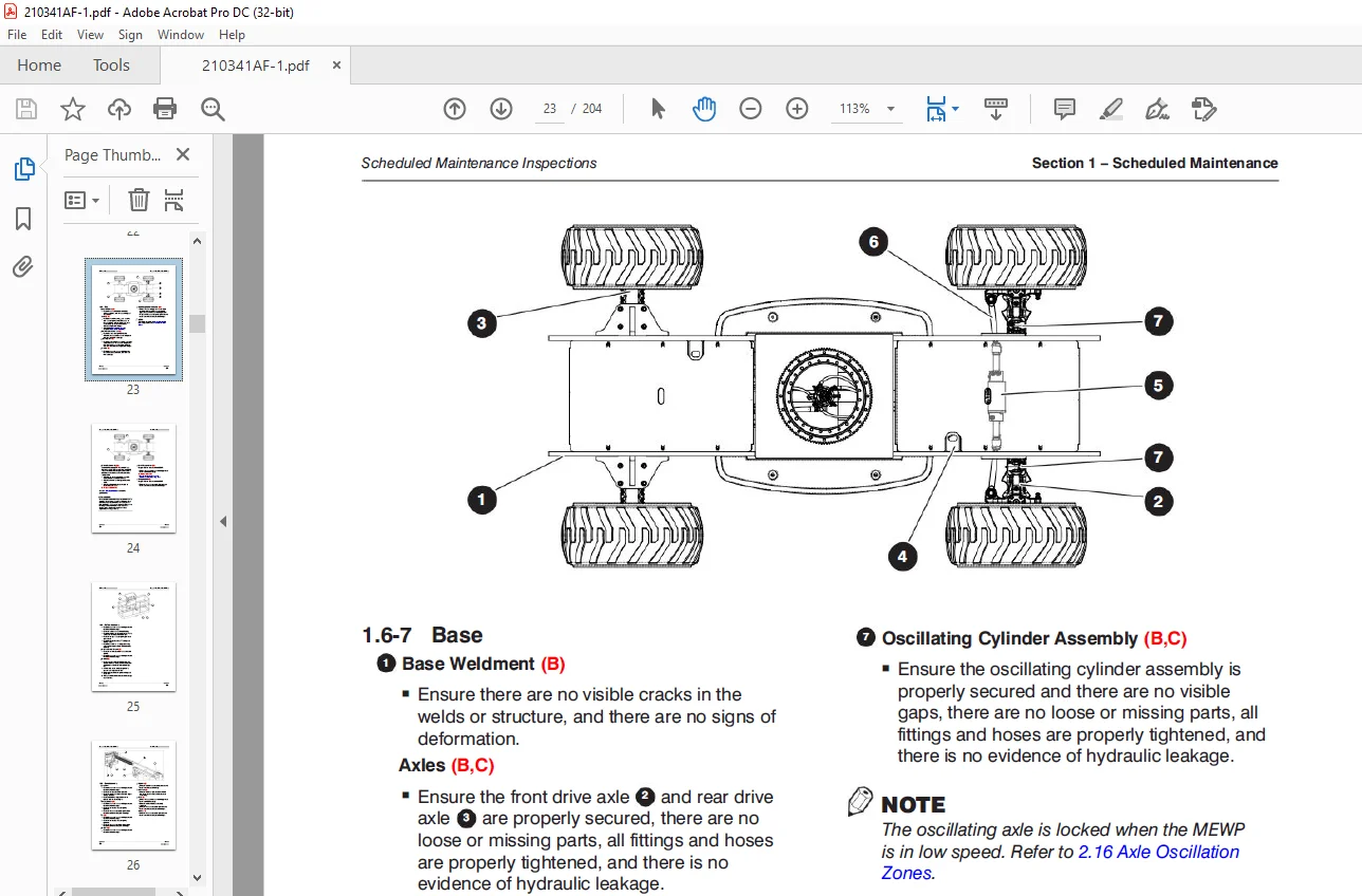
Scheduled Maintenance:
1.1 Read and Heed:
Skyjack is continuously improving and expanding product features on its equipment, therefore,
specifications and dimensions are subject to change without notice.
1.1 Read and Heed:
Skyjack is continuously improving and expanding product features on its equipment, therefore,
specifications and dimensions are subject to change without notice.
1.1-1 Mobile Elevating Work Platform (MEWP) Definition:
A MEWP is a mobile device that has a positionable platform supported from ground level by a
structure.
A MEWP is a mobile device that has a positionable platform supported from ground level by a
structure.
1.1-2 Purpose of Equipment:
The Skyjack Articulating Boom Series MEWPs are designed to transport and raise personnel, tools and
materials to overhead work areas.
The Skyjack Articulating Boom Series MEWPs are designed to transport and raise personnel, tools and
materials to overhead work areas.
1.1-3 Use of Equipment:
The MEWP is a highly maneuverable, mobile work station. Work platform elevation and elevated
driving must only be done on a firm surface.
The MEWP is a highly maneuverable, mobile work station. Work platform elevation and elevated
driving must only be done on a firm surface.
1.1-4 Manual:
Operating Manual: The operating manual is considered a fundamental part of the MEWP. It is a very
important way to communicate necessary safety information to users and operators. A complete
and legible copy of this manual must be kept in the provided weather-resistant storage compartment
on the MEWP at all times.
Service & Maintenance:
- The purpose of this is to provide the customer with the servicing and
maintenance procedures essential for the promotion of proper machine operation for its intended
purpose. - All information in this manual should be read and understood before any attempt is made to service
the machine.
1.1-5 Service Policy and Warranty:
Skyjack warrants each new product to be free of defective parts and workmanship for the first 2
years or 3000 hours, whichever occurs first. Any defective part will be replaced or repaired by
your local Skyjack dealer at no charge for parts or labor. In addition,
all products have a 5 year structural warranty. Contact the Skyjack Service Department for warranty
statement extensions or exclusions.
1.1-6 Operator Safety Reminders, Warnings and Precautions:
Operator safety is Skyjack’s priority. The operator should comply with all applicable
safety-related reminders, warnings and precautions found in the Operating Manual. They should be
read and understood completely before operating the MEWP.
Operator safety is Skyjack’s priority. The operator should comply with all applicable
safety-related reminders, warnings and precautions found in the Operating Manual. They should be
read and understood completely before operating the MEWP.
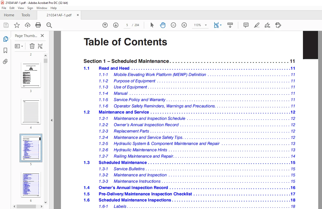
TABLE OF CONTENTS:
Skyjack SJ85 AJ Articulating Boom Service Manual 210341AF – PDF DOWNLOAD
Table of Contents....................................................................................... 5 Section 1 – Scheduled Maintenance....................................................................... 11 1.1 Read and Heed.................................................................................. 11 1.1-1 Mobile Elevating Work Platform (MEWP) Definition.......................................... 11 1.1-2 Purpose of Equipment...................................................................... 11 1.1-3 Use of Equipment.......................................................................... 11 1.1-4 Manual.................................................................................... 11 1.1-5 Service Policy and Warranty............................................................... 11 1.1-6 Operator Safety Reminders, Warnings and Precautions....................................... 11 1.2 Maintenance and Service........................................................................ 12 1.2-1 Maintenance and Inspection Schedule....................................................... 12 1.2-2 Owner’s Annual Inspection Record.......................................................... 12 1.2-3 Replacement Parts......................................................................... 12 1.2-4 Maintenance and Service Safety Tips....................................................... 12 1.2-5 Hydraulic System & Component Maintenance and Repair....................................... 13 1.2-6 Hydraulic Maintenance Hints............................................................... 13 1.2-7 Railing Maintenance and Repair............................................................ 14 1.3 Scheduled Maintenance.......................................................................... 15 1.3-1 Service Bulletins......................................................................... 15 1.3-2 Maintenance and Inspection................................................................ 15 1.3-3 Maintenance Instructions.................................................................. 15 1.4 Owner’s Annual Inspection Record............................................................... 16 1.5 Pre-Delivery/Maintenance Inspection Checklist.................................................. 17 1.6 Scheduled Maintenance Inspections.............................................................. 18 1.6-1 Labels (B)................................................................................ 18 1.6-2 Electrical................................................................................ 18 1.6-3 Limit Switches (B)........................................................................ 18 1.6-4 Hydraulic................................................................................. 18 1.6-5 Engine Compartment........................................................................ 19 1.6-6 Control Compartment....................................................................... 21 1.6-7 Base...................................................................................... 23 1.6-8 Platform Assembly ........................................................................ 25 1.6-9 Boom Assembly............................................................................. 26 1.6-10 Optional Equipment/Attachments........................................................... 27 1.7 Function Tests................................................................................. 28 Section 2 – Maintenance Tables and Diagrams............................................................. 29 2.1 Standard Hose Numbering System................................................................. 29 2.2 Torque Specifications for Fasteners (US)....................................................... 31 2.3 Torque Specifications for Fasteners (Metric)................................................... 32 2.4 Torque Specifications for Hydraulic Couplings & Hoses.......................................... 33 2.5 Axle Torque Specifications..................................................................... 34 2.6 Axle Maintenance Intervals..................................................................... 35 2.7 MEWP Torque Specifications..................................................................... 36 2.8 Tire Specifications............................................................................ 37 2.9 Floor Loading Pressure......................................................................... 38 2.10 Specifications & Features - Dimensional Data.................................................. 39 2.11 Specifications and Features - Performance & Speeds............................................ 40 2.12 Hydraulic Specifications...................................................................... 41 2.13 Specifications and Features - Engines & Fluids................................................ 42 2.14 Reach......................................................................................... 43 2.15 Dimensions.................................................................................... 44 2.16 Axle Oscillation Zones........................................................................ 44 Section 3 – System Component Identification and Schematics.............................................. 45 3.1 Electrical Symbol Chart........................................................................ 46 3.2 Hydraulic Symbol Chart......................................................................... 47 3.3 Wire Number and Color Code..................................................................... 48 3.4 Wire Numbers and Color Codes - Additional...................................................... 49 3.5 Hydraulic Parts List........................................................................... 50 3.6 Electrical Parts List.......................................................................... 53 3.7 Brake Manifold Port Identification............................................................. 57 3.8 Jib Manifold Port Identification............................................................... 58 3.9 Main Manifold - Hose Port Identification....................................................... 59 3.10 Main Manifold - Hydraulic Components.......................................................... 60 3.11 Main Manifold - Electrical Components......................................................... 61 3.12 SGE Harness Connection........................................................................ 62 3.13 Platform & Jib Harness Connection............................................................. 63 3.14 Footswitch Harness Connection................................................................. 64 3.15 Main Manifold Harness......................................................................... 65 3.16 Platform to Base Control Cables............................................................... 66 3.17 Engine Control Wiring - Deutz TD2.9L.......................................................... 67 3.18 Engine Control Wiring - Deutz D2011........................................................... 68 3.19 Engine Control Wiring - Kubota WG3800......................................................... 69 3.20 Engine Control Wiring - Perkins 2.2TA......................................................... 70 3.21 Anti-Overrising Limit Switch Harnesses - KC................................................... 71 3.22 Deutz EDC-F Harness........................................................................... 72 3.23 Load Cell Wiring.............................................................................. 73 3.24 Hydraulic Schematic........................................................................... 75 3.25 Electrical Schematic - ANSI/CSA & AS.......................................................... 76 3.26 Electrical Schematic - CE..................................................................... 77 3.27 Electrical Schematic - KC..................................................................... 78 3.28 Platform Controls Wiring...................................................................... 79 3.29 Platform Controls - Harness View.............................................................. 80 3.30 Platform Controls - Schematic View............................................................ 81 3.31 Base Controls Wiring - ANSI/CSA & AS.......................................................... 82 3.32 Base Controls Wiring - ANSI/CSA with Positive Air Shut-off Option............................. 83 3.33 Base Controls Wiring - CE..................................................................... 84 3.34 Base Controls Wiring - KC..................................................................... 85 3.35 Engine Schematic - Deutz TD2.9L............................................................... 86 3.36 Engine Schematic - Deutz D2011................................................................ 87 3.37 Engine Schematic - Perkins 2.2TA.............................................................. 88 3.38 Engine Schematic - Kubota WG3800.............................................................. 89 3.39 Engine Harness - Deutz TD2.9L................................................................. 90 3.40 Engine Harness - Perkins 2.2TA................................................................ 91 3.41 Engine Harness - Kubota WG3800................................................................ 92 Section 4 – Troubleshooting Information................................................................. 93 4.1 Introduction................................................................................... 93 4.2 Electrical System.............................................................................. 94 4.2-1 All Controls Inoperative................................................................. 94 4.2-2 No Power.................................................................................. 97 4.2-3 Engine will not Crank..................................................................... 97 4.2-4 No Boom Up or Down........................................................................ 99 4.2-5 No Riser Up or Down.......................................................................102 4.2-6 No Turret Rotate..........................................................................104 4.2-7 No Telescope..............................................................................106 4.2-8 No Platform Level.........................................................................109 4.2-9 No Jib Up or Down.........................................................................111 4.2-10 No Platform Rotate.......................................................................113 4.2-11 No Platform Rotate or Jib Functions......................................................115 4.2-12 No Drive or Steer........................................................................116 4.2-13 Direction Sensing Inoperative............................................................118 4.2-14 Green LED on Load Sense/Dual Load Zone Module is not On..................................119 4.2-15 Load Sense Indicates Overload or Overload Warning with Platform Empty or Below Weight....119 4.2-16 Load Sense/Dual Load Zone Module Error...................................................120 4.2-17 No Light/Alarm when Platform is Overloaded...............................................121 4.3 Hydraulic System...............................................................................122 4.3-1 All Controls Inoperative..................................................................122 4.3-2 All Boom Functions Inoperative............................................................122 4.3-3 No Main Boom Up or Down...................................................................122 4.3-4 No Turret Rotate..........................................................................124 4.3-5 No Boom Extend or Retract.................................................................125 4.3-6 No Riser Up or Down.......................................................................126 4.3-7 No Platform Level.........................................................................127 4.3-8 No Jib Up or Down.........................................................................128 4.3-9 No Platform Rotate........................................................................129 4.3-10 No Steer.................................................................................130 4.3-11 No Drive.................................................................................131 4.3-12 No Brake Function........................................................................132 4.3-13 No Oscillating Axle Function.............................................................133 Section 5 – Procedures..................................................................................135 5.1 General........................................................................................135 5.1-1 Safety and Workmanship....................................................................135 5.2 Platform.......................................................................................136 5.2-1 Human Machine Interface (HMI).............................................................136 5.1-2 User Interface Keys.......................................................................136 5.1-3 SCM Character Functions...................................................................137 5.1-4 SCM Operating Values......................................................................138 5.1-5 How to Unlock and Modify SCM Settings.....................................................141 5.1-6 Check I/O Error...........................................................................143 5.1-7 Fly Boom Switch Voltage References........................................................144 5.1-8 Platform Controller Voltage References....................................................145 5.1-9 Remove the Platform.......................................................................147 5.1-10 Reinstall the Platform...................................................................148 5.3 Boom...........................................................................................149 5.3-1 Check the Wear Pads.......................................................................149 5.3-2 Shim the Wear Pads........................................................................149 5.3-3 Torque the Rotary Actuator Bolts..........................................................149 5.3-4 Remove the Jib............................................................................150 5.3-5 Install the Jib...........................................................................150 5.3-6 Limit Switch Locations....................................................................151 5.4 Turret.........................................................................................152 5.4-1 Checkand Replace the High Pressure Filter.................................................152 5.4-2 Adjust the Turret Rotation Gear Backlash..................................................152 5.4-3 Check the Swing Drive Oil.................................................................153 5.4-4 Change the Swing Drive Oil................................................................153 5.4-5 Replace the Battery.......................................................................154 5.4-6 Turret Rotation Gear Bolt Torque Sentence.................................................154 5.4-7 Electronic Tilt Switch Setup..............................................................155 5.4-8 Check the Rotation Bearing for Axial Wear.................................................157 5.4-9 Reset the Emergency Lowering Counter (CE only)............................................158 5.5 Deutz Diesel Engines...........................................................................159 5.5-1 Replace the Engine Oil and Filter.........................................................159 5.5-2 Replace the Fuel Filter...................................................................160 5.5-3 Replace the Air Filter....................................................................160 5.5-4 Check the Engine Belt.....................................................................160 5.5-5 Checking the Oil Cooler (Deutz D2011 only)................................................160 5.7-13 Deutz TD2.9L Fault Codes.................................................................161 5.6 Hydraulic Tank.................................................................................181 5.6-1 Change the Hydraulic Tank Filter..........................................................181 5.6-2 Change the Hydraulic Oil..................................................................181 5.7 Manifolds and Hydraulic Pumps..................................................................182 5.7-1 Hydraulic Brake Pressure Adjustment.......................................................182 5.7-2 Hydraulic Standby Pressure Adjustment.....................................................183 5.7-3 Hydraulic High Pressure Adjustment........................................................184 5.7-4 Hydraulic System Relief Valve Adjustment..................................................185 5.7-5 Turret Rotate Relief Valve Adjustment.....................................................186 5.7-6 Platform Level Relief Valve Adjustment....................................................186 5.7-7 Riser Relief Valve Adjustment.............................................................187 5.7-8 Main Boom Relief Valve Adjustment.........................................................187 5.7-9 Fly Boom Relief Valve Adjustment..........................................................188 5.7-10 Test the Charge Pump Pressure on the Drive Pump..........................................188 5.7-11 Test the Forward Drive Pressure on the Drive Pump........................................189 5.7-12 Testi the Reverse Drive Pressure on the Drive Pump.......................................189 5.8 Axles..........................................................................................190 5.8-1 Change the Axle Oil ......................................................................190 5.8-2 Check the Oil Level in the Torque Hubs....................................................190 5.8-3 Change the Oil in the Torque Hubs.........................................................190 5.8-4 Check the Oil Level in the Axle Gearbox...................................................191 5.8-5 Change the Oil in the Axle Gearbox........................................................191 5.8-6 Inspect the Brakes........................................................................192 5.8-7 Replace the Oscillating Cylinder Bolts....................................................192 5.8-8 Replace the Oscillating Cylinder..........................................................193 5.8-9 Bleeding the Cylinders of the Oscillating Axle ...........................................194 5.8-10 Test the Oscillating Axle Cylinders......................................................195 5.9 Grease Points..................................................................................196 5.9-1 Grease the Turret Ring Gear...............................................................196 5.9-2 Grease the Turret Swing Drive.............................................................196 5.9-3 Grease the Axles..........................................................................197 5.9-4 Grease the Drive Shaft....................................................................197 5.10 Load Sensing System...........................................................................198 5.10-1 Load Sensing System Overload Status......................................................198 5.10-2 Dual Capacity Overload Module Function Table.............................................199 5.10-3 Calibrate the Load Sensing System........................................................200
IMAGES PREVIEW OF THE MANUAL:
Customer Support: [email protected]
https://vimeo.com/877785889?share=copy
PLEASE NOTE:
- This is the SAME MANUAL used by the dealerships to diagnose your vehicle
- No waiting for couriers / posts as this is a PDF manual and you can download it within 2 minutes time once you make the payment.
- Your payment is all safe and the delivery of the manual is INSTANT – You will be taken to the DOWNLOAD PAGE.
- So have no hesitations whatsoever and write to us about any queries you may have : heydownloadss @gmail.com
S.V