Skyjack SJ8831 RT SJ8841 RT Rough Terrain Scissors Service Manual 163762AHA – PDF DOWNLOAD
$27.95
Skyjack SJ8831 RT SJ8841 RT Rough Terrain Scissors Service Manual 163762AHA – PDF DOWNLOAD
SJRT 8831 36000276 – 36999999
SJRT 8841 40001135 – 40999999
Description
Skyjack SJ8831 RT SJ8841 RT Rough Terrain Scissors Service Manual 163762AHA – PDF DOWNLOAD
FILE DETAILS:
Skyjack SJ8831 RT SJ8841 RT Rough Terrain Scissors Service Manual 163762AHA – PDF DOWNLOAD
Language : English
Pages : 171
Downloadable : Yes
File Type : PDF
DESCRIPTION:
Skyjack SJ8831 RT SJ8841 RT Rough Terrain Scissors Service Manual 163762AHA – PDF DOWNLOAD
SJRT 8831 36000276 – 36999999
SJRT 8841 40001135 – 40999999
1.1 Read and Heed:
SKYJACK is continuously improving and expanding product features on its equipment, therefore,
specifications and dimensions are subject to change without notice.
A mobile device that has a positionable platform supported from ground level by a structure.
The SKYJACK SJ DC Electric Series MEWPs are designed to transport and raise personnel, tools and
materials to overhead work areas.
The MEWP is a highly maneuverable, mobile work station. Work platform elevation and elevated
driving must only be done on a firm, level surface.
Operating Manual: The operating manual is considered a fundamental part of the aerial platform. It
is a very important way to communicate necessary safety information to users and operators. A
complete and legible copy of this manual must be kept in the provided weather-resistant storage
compartment on the aerial platform at all times.
Service & Maintenance:
- The purpose of this is to provide the customer with the servicing and
maintenance procedures essential for the promotion of proper machine operation for its intended
purpose. - All information in this manual should be read and understood before any attempt is made to service
the machine.
SKYJACK warrants each new product to be free of defective parts and workmanship for the first 2
years or 3000 hours, whichever occurs first. Any defective part will be replaced or repaired by
your local SKYJACK dealer at no charge for parts or labor. In addition, all products have a 5 year
structural warranty. Contact the SKYJACK Service Department
for warranty statement extensions or exclusions.
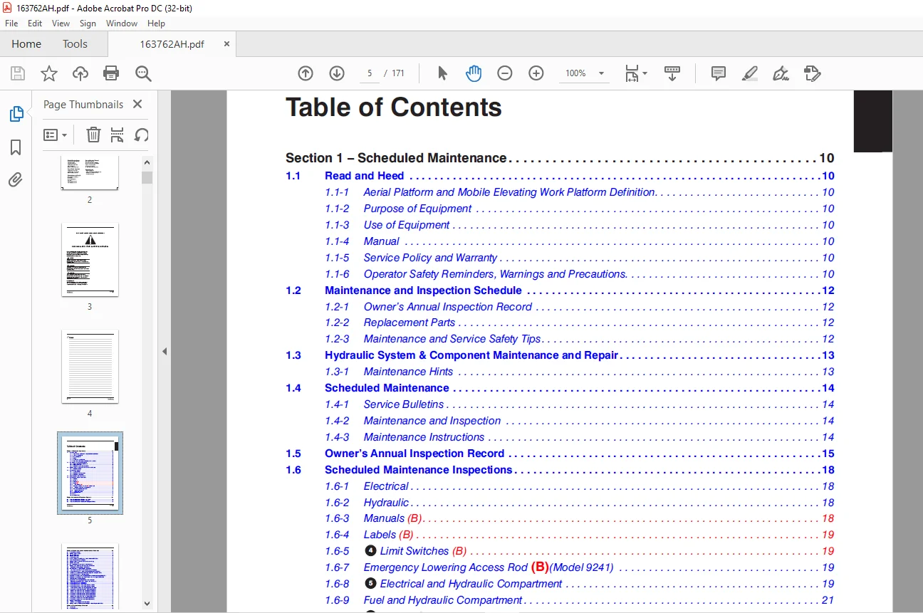
TABLE OF CONTENTS:
Skyjack SJ8831 RT SJ8841 RT Rough Terrain Scissors Service Manual 163762AHA – PDF DOWNLOAD
Section 1 – Scheduled Maintenance 10
1 1 Read and Heed 10
1 1-1 Aerial Platform and Mobile Elevating Work Platform Definition 10
1 1-2 Purpose of Equipment 10
1 1-3 Use of Equipment 10
1 1-4 Manual 10
1 1-5 Service Policy and Warranty 10
1 1-6 Operator Safety Reminders, Warnings and Precautions 10
1 2 Maintenance and Inspection Schedule 12
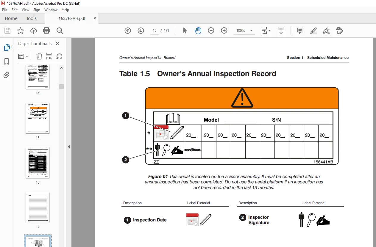
1 2-1 Owner’s Annual Inspection Record 12
1 2-2 Replacement Parts 12
1 2-3 Maintenance and Service Safety Tips 12
1 3 Hydraulic System & Component Maintenance and Repair 13
1 3-1 Maintenance Hints 13
1 4 Scheduled Maintenance 14
1 4-1 Service Bulletins 14
1 4-2 Maintenance and Inspection 14
1 4-3 Maintenance Instructions 14
1 5 Owner’s Annual Inspection Record 15
1 6 Scheduled Maintenance Inspections 18
1 6-1 Electrical 18
1 6-2 Hydraulic 18
1 6-3 Manuals (B) 18
1 6-4 Labels (B) 19
1 6-5 4 Limit Switches (B) 19
1 6-7 Emergency Lowering Access Rod (B)(Model 9241) 19
1 6-8 5 Electrical and Hydraulic Compartment 19
1 6-9 Fuel and Hydraulic Compartment 21
1 6-10 1 Engine Compartment 22
1 6-11 1 Platform Assembly 24
1 6-12 Lifting Mechanism 25
1 6-13 Base 28
1 6-15 Function Tests 30
Section 2 – Maintenance Tables and Diagrams 31
2 1 Torque Specifications for Fasteners (Imperial) 40
2 2 Torque Specifications for Fasteners (Metric) 41
2 3 Torque Specifications for Hydraulic Couplings and Hoses 42
Table of Contents
6
163762AHA SJ8831 RT SJ8841 RT
Section 3 – System Component Identification and Schematics 43
3 1 Electrical Symbol Chart 44
3 2 Hydraulic Symbol Chart 45
3 3 AC Cord Color Code 46
3 4 Hydraulic Parts List 47
3 5 Electrical Parts List 49
3 6 Platform Control Console Diagram with All Options (ANSI/CSA) 54
3 7 Control Cable Assemblies Diagram 55
3 8 Outrigger/Hydraulic Generator Control Console Wiring 56
3 9 Hydraulic Schematic 57
3 10 Main Manifold Components and Port Identifications 58
3 11 Hydraulic Manifold Components and Port Identifications 59
3 12 Main Manifold Wiring Diagram (ANSI/CSA) 60
3 13 Horn, Light, Beeper Wiring Diagram (ANSI/CSA) 61
3 14 Powered Extension Platform – Electrical Connection Diagram 62
3 15 Electrical Panel Diagram – 12 kW Generator Modification (ANSI/CSA) 63
3 16 12 kW Generator Hydraulic and Electric Wiring Schematics (ANSI/CSA) 64
3 17 Electrical Panel Diagram – Outrigger Option 65
3 18 Engine Interface Harness Wiring Diagram – Kubota Dual Fuel Engine (DF972 EFI) 66
3 19 Engine Interface Electrical Schematic – Kubota Dual Fuel Engine (DF972 EFI) 67
3 20 Telematics Harness Wiring Diagram 68
3 21 Engine Harness Wiring Diagram – Kubota Diesel Engine 71
3 22 Engine Harness Wiring Diagram – Kubota Dual Fuel Engine 72
3 23 Electrical Panel Diagram (ANSI/CSA) 73
3 24 Electrical Panel Diagram (ANSI/CSA) 74
3 25 Electrical Panel Diagram with Positive Air Shutoff Option 75
3 26 Electrical Panel Diagram with Positive Air Shutoff Option 76
3 27 Positive Air Shutoff Harness Wiring Diagram – Diesel Engine 77
3 28 Electrical Schematic – Dual Fuel – No Options (ANSI/CSA) 78
3 29 Electrical Schematic – Dual Fuel – No Options (ANSI/CSA) 79
3 30 Electrical Schematic – Dual Fuel – No Options (ANSI/CSA) 80
3 31 Electrical Schematic – Dual Fuel – All Options (ANSI/CSA) 81
3 32 Electrical Schematic – Dual Fuel – All Options (ANSI/CSA) 82
3 33 Electrical Schematic – Dual Fuel – All Options (ANSI/CSA) 83
3 34 Electrical Schematic – Diesel – All Options (ANSI/CSA) 84
3 35 Electrical Schematic – Diesel – All Options (ANSI/CSA) 85
3 36 Outrigger Wiring Diagram 86
3 37 Electrical Panel Diagram – Oil Cooler Option 87
3 38 Hydraulic Generator Electrical Panel Diagram – Kubota Engine (ANSI/CSA) 88
Section 4 – Troubleshooting Information 89
4 1 Introduction 89
4 2 Electrical System 90
7
SJ8831 RT SJ8841 RT 163762AHA
4 2-1 All Controls Inoperative 90
4 2-2 No Power to Platform (ANSI/CSA) 90
4 2-3 All Functions Inoperative from Platform 91
4 2-4 Engine Does Not Crank from Platform 91
4 2-5 Engine Does Not Crank from Base Controls (Kubota diesel) 92
4 2-6 Engine Cranks but Stops Cranking after a few seconds 92
4 2-7 Glow Plugs Inoperative from Engine Controls 92
4 2-8 Glow Plugs Inoperative from Platform (Additional) 92
4 2-9 Engine Cranks but Does Not Start (Kubota diesel) 93
4 2-10 High Throttle Inoperative 93
4 2-11 Drive and Steer Inoperative (Machines without outriggers option) 94
4 2-12 Drive and Steer Inoperative (machines with outriggers option) 94
4 2-13 Brakes Do Not Release 95
4 2-14 Steer Right Inoperative 96
4 2-15 Steer Left Inoperative 96
4 2-16 Reverse Drive Inoperative 97
4 2-17 Forward Drive Inoperative 98
4 2-18 First Drive Speed and Steering Inoperative 98
4 2-19 Second Drive Speed Inoperative 98
4 2-20 Third Drive Speed Inoperative 100
4 2-21 High/Low Range Speed Inoperative 100
4 2-22 Up Circuit Inoperative from Platform or Base (machines without outriggers) 101
4 2-23 Up Circuit Inoperative from Base 102
4 2-24 Platform Does Not Lift from Platform or Base Controls with Outriggers Retracted
(Lift Operates Correctly with Outriggers Extended) 102
4 2-25 Platform Does Not Lift from Platform or Base Controls with Outriggers Extended 103
4 2-26 Down Circuit Inoperative from Platform or Base 104
4 2-27 Down Circuit Inoperative from Base 105
4 2-28 Powered Extension Platform Inoperative 105
4 2-29 Powered Extension Platform Does Not Extend 106
4 2-30 Powered Extension Platform Does Not Retract 106
4 2-31 Hydraulic Generator Inoperative 107
4 2-32 Hydraulic Generator Does Not Shut Off from Generator Switch 107
4 2-33 All Outriggers Inoperative (Auto-level and manual) 108
4 2-34 All Outriggers Inoperative (Auto-level and manual from platform controls) 108
4 2-35 All Outriggers Inoperative (Base controls) 109
4 2-36 All Outriggers Inoperative (Auto-level)
A: Led Power Indicator Light at Outrigger Control Module (OCM1) Not on Constant 109
4 2-37 All Outriggers Inoperative (Auto Level Only)
B: Led Power Indicator Light at Outrigger Control Module (OCM1) Flashing 110
4 2-38 Left Front Outrigger Inoperative Manually 111
4 2-39 Right Front Outrigger Inoperative Manually 111
4 2-40 Right Rear Outriggers Inoperative Manually 111
8
163762AHA SJ8831 RT SJ8841 RT
4 2-41 Left Rear Outriggers Inoperative Manually 112
4 2-42 Individual Outrigger Functions Inoperative (auto-level) 112
4 2-43 Auto-level Inoperative 112
4 2-44 Auto All Up Inoperative (Retract) 113
4 3 Hydraulic System 114
4 3-1 All Functions Inoperative 114
4 3-2 Steering Inoperative 114
4 3-3 Steer and First Drive Speed Inoperative 114
4 3-4 Lift and Second Drive Speed Inoperative 114
4 3-5 Drive Inoperative 114
4 3-6 Reverse Drive Inoperative 115
4 3-7 Forward Drive Inoperative 115
4 3-8 Brakes Do Not Release 115
4 3-9 Up Circuit Inoperative 115
4 3-10 Down Circuit Inoperative 116
4 3-11 Powered Extension Platform Inoperative 116
4 3-12 Hydraulic Generator Inoperative 116
4 3-13 All Outriggers Inoperative 116
4 3-14 Left Front Outrigger Inoperative 116
4 3-15 Right Front Outrigger Inoperative 117
4 3-16 Right Rear Outrigger Inoperative 117
4 3-17 Left Rear Outrigger Inoperative 117
4 3-18 Outriggers Drift In 117
Section 5 – Procedures 119
5 1 Base 120
5 1-1 Brake Caliper Adjustment 120
5 1-2 Bleeding the Brake Caliper 122
5 1-3 Changing the Hydraulic Oil 124
5 1-4 Wheel Bolt / Nut Inspection and Torquing Procedure 125
5 1-5 Wheel Reinstallation and Torquing Procedure 125
5 1-6 Front Axle Hub Procedure 126
5 1-7 Electronic Tilt Switch Setup Procedure 128
5 1-8 Reconnecting the Platform Control Box for Use from the Ground 131
5 1-9 Tightening and Torque Recommendations for Hydraulic Couplings and Hoses 132
5 1-10 Checking the Holding Valve 133
5 1-11 System Pressure Setting 134
5 1-12 Lift Pressure Setting 135
5 1-13 Grease Points 136
5 2 Engines 138
5 2-1 Kubota Dual Fuel (DF972) Resistance Checks 138
5 2-2 Kubota Dual Fuel (DF972) Engine Throttle Setting 139
5 2-3 Kubota Diesel (D1305) Engine Throttle Setting 140
9
SJ8831 RT SJ8841 RT 163762AHA
5 2-4 Fan Belt Replacement and Adjustment 142
5 2-5 Replacing the Air Cleaner Element 143
5 2-6 Replacing the Fuel Filter Element (Kubota D1305) 144
5 2-7 Bleeding the Fuel System of Air (Kubota D1305) 144
5 2-8 Replacing the Oil Filter Cartridge 145
5 2-9 Changing the Oil 145
5 2-10 Checking and Replenishing the Radiator Coolant Level 146
5 2-11 Draining and Refilling the Radiator 146
5 2-12 Engine Parameter Display 147
5 3 Outriggers 155
5 3-1 Auto-Leveling Outrigger PC Board Layout 155
5 3-2 Outrigger Mechanical Limit Switch Wiring Diagram 156
5 3-3 Auto-Leveling Outrigger Setting and Error Codes 157
5 3-4 Hand Held Calibration/Diagnostic Tool Key Functions 159
5 3-5 Outrigger Control Module Instructions 160
5 3-6 Auto-Leveling Outrigger Control Module Pin Reference Chart 163
5 3-7 Outrigger Upper Limit Switch (LS61, LS62, LS63, LS64) Replacement and Adjustment 164
5 3-8 Outrigger Lower Limit Switch (LS65, LS66, LS67, LS68) Replacement and Adjustment 165
5 4 Scissors 167
5 4-1 End of Stroke Limit Switch (LS4) Replacement and Adjustment 167
5 4-2 High Speed Cutout Limit Switch (LS5) Replacement and Adjustment 169
5 5 Platform 170
5 5-1 Gate Springe Hinge Adjustment 170
IMAGES PREVIEW OF THE MANUAL:
Need help? Contact: [email protected]
PLEASE NOTE:
- This is the same manual used by the DEALERSHIPS to SERVICE your vehicle.
- The manual can be all yours – Once payment is complete, you will be taken to the download page from where you can download the manual. All in 2-5 minutes time!!
- Need any other service / repair / parts manual, please feel free to contact us at heydownloadss @gmail.com . We may surprise you with a nice offer
S.V