Skyjack SJIII 3220 SJIII 3226 SJIII 4620 SJIII 4626 SJIII 4632 DC ELECTRIC SCISSORS SERVICE MANUAL 157928AM – PDF DOWNLOAD
$26.95
Skyjack SJIII 3220 SJIII 3226 SJIII 4620 SJIII 4626 SJIII 4632 DC ELECTRIC SCISSORS SERVICE MANUAL 157928AM – PDF DOWNLOAD
Serial Number(s):
SJIII 3220 60 002 259 to 60 999 999
SJIII 3226 27 006 432 to 27 999 999
SJIII 46xx 70 007 139 to 70 999 999
Description
Skyjack SJIII 3220 SJIII 3226 SJIII 4620 SJIII 4626 SJIII 4632 DC ELECTRIC SCISSORS SERVICE MANUAL 157928AM – PDF DOWNLOAD
FILE DETAILS:
Skyjack SJIII 3220 SJIII 3226 SJIII 4620 SJIII 4626 SJIII 4632 DC ELECTRIC SCISSORS SERVICE MANUAL 157928AM – PDF DOWNLOAD
Language : English
Pages :189
Downloadable : Yes
File Type : PDF
DESCRIPTION:
Skyjack SJIII 3220 SJIII 3226 SJIII 4620 SJIII 4626 SJIII 4632 DC ELECTRIC SCISSORS SERVICE MANUAL 157928AM – PDF DOWNLOAD
Serial Number(s):
SJIII 3220 60 002 259 to 60 999 999
SJIII 3226 27 006 432 to 27 999 999
SJIII 46xx 70 007 139 to 70 999 999
and dimensions are subject to change without notice.
Aerial Platform and Mobile Elevating Work Platform Definition
A mobile device that has a positionable platform supported from ground level by a structure.
Purpose of Equipment
The SKYJACK SJIII DC Electric series aerial platforms are designed to transport and raise personnel, tools and
materials to overhead work areas.
Use of Equipment
The aerial platform is a highly maneuverable, mobile work station. Work platform elevation and elevated driving
must only be done on a firm level surface.
Operating
The operating manual is considered a fundamental part of the aerial platform. It is a very important way to
communicate necessary safety information to users and operators. A complete and legible copy of this manual
must be kept in the provided weather-resistant storage compartment on the aerial platform at all times.
Service & Maintenance
The purpose of this is to provide the customer with the servicing and maintenance procedures essential for
the promotion of proper machine operation for its intended purpose.
All information in this manual should be read and understood before any attempt is made to service the machine.
The updated copy of the manuals are found on the company’s
IMAGES PREVIEW OF THE MANUAL:
TABLE OF CONTENTS:
Skyjack SJIII 3220 SJIII 3226 SJIII 4620 SJIII 4626 SJIII 4632 DC ELECTRIC SCISSORS SERVICE MANUAL 157928AM – PDF DOWNLOAD
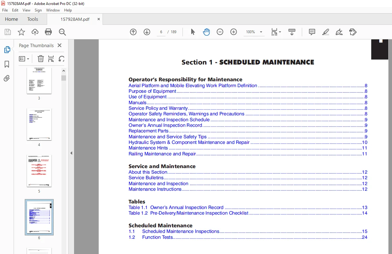
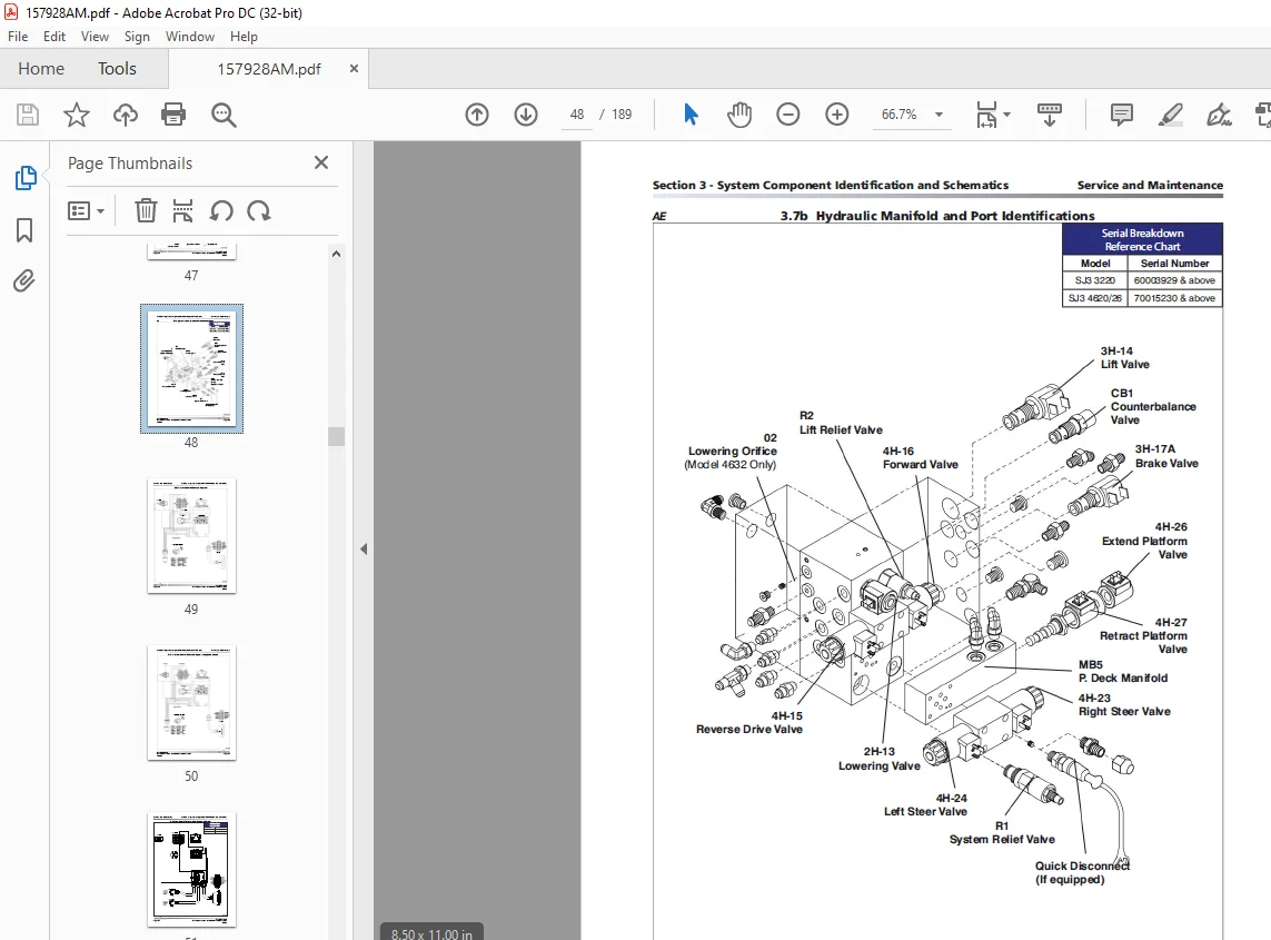
Cover..........................................................................................................................  2
Table of Contents..............................................................................................................  4
Section 1 - scheduled maintenance..............................................................................................  6
	Operator’s Responsibility for Maintenance..................................................................................  8
		Aerial Platform and Mobile Elevating Work Platform Definition..........................................................  8
		Purpose of Equipment...................................................................................................  8
		Use of Equipment.......................................................................................................  8
		Manuals................................................................................................................  8
		Service Policy and Warranty............................................................................................  8
		Operator Safety Reminders, Warnings and Precautions....................................................................  8
		Maintenance and Inspection Schedule....................................................................................  9
		Owner’s Annual Inspection Record.......................................................................................  9
		Replacement Parts......................................................................................................  9
		Maintenance and Service Safety Tips....................................................................................  9
		Hydraulic System & Component Maintenance and Repair.................................................................... 10
		Maintenance Hints...................................................................................................... 11
		Railing Maintenance and Repair......................................................................................... 11
	Service and Maintenance.................................................................................................... 12
		About this Section..................................................................................................... 12
		Service Bulletins...................................................................................................... 12
		Maintenance and Inspection............................................................................................. 12
		Maintenance Instructions............................................................................................... 12
	Tables..................................................................................................................... 13
		Table 1.1  Owner’s Annual Inspection Record............................................................................ 13
		Table 1.2  Pre-Delivery/Maintenance Inspection Checklist............................................................... 14
	Scheduled Maintenance...................................................................................................... 15
		1.1 Scheduled Maintenance Inspections.................................................................................. 15
		1.2 Function Tests..................................................................................................... 24
Section 2 - maintenance tables and diagrams.................................................................................... 26
	Tables..................................................................................................................... 26
		Table 2.1  Specifications and Features................................................................................. 27
		Table 2.1  Specifications and Features (Continued)..................................................................... 28
		Table 2.2  Floor Loading Pressure...................................................................................... 29
		Floor Loading Pressure................................................................................................. 30
		Table 2.3  Maximum Platform Capacities (Evenly Distributed)............................................................ 31
		Table 2.4  Torque Specifications....................................................................................... 32
		Table 2.5  Torque Specifications for Fasteners (Imperial).............................................................. 33
		Table 2.6  Torque Specifications for Fasteners (Metric)................................................................ 34
		Table 2.7  Torque Specifications for Hydraulic Couplings & Hoses....................................................... 35
Section 3 - System component idenTification and schematics..................................................................... 36
	Charts..................................................................................................................... 38
		3.1  Electrical Symbol Chart........................................................................................... 38
		3.2  Hydraulic Symbol Chart............................................................................................ 39
		3.3  Wire Number and Color Code........................................................................................ 40
		3.4  AC Cord Color Code................................................................................................ 41
	Parts List................................................................................................................. 42
		3.5  Hydraulic Schematic Parts List.................................................................................... 42
		3.5  Hydraulic Schematic Parts List (Continued)........................................................................ 43
		3.6  Electrical Components Parts List.................................................................................. 44
		3.6a  Electrical Component Parts List (Continued)...................................................................... 45
		3.6b  Electrical Component Parts List (Continued)...................................................................... 46
		3.7a  Hydraulic Manifold and Port Identifications...................................................................... 47
		3.7b  Hydraulic Manifold and Port Identifications...................................................................... 48
	Diagrams and Schematics.................................................................................................... 49
		3.8a  Platform Control Console Diagram................................................................................. 49
		3.8b  Platform Control Console Diagram - Long Cable Option............................................................. 50
		3.9a  Powerdeck Platform Modification Diagram.......................................................................... 51
		3.9b  Powerdeck Platform Modification Diagram.......................................................................... 52
		3.10  Powered Extension Platform Control Console and Harness........................................................... 53
		3.11a  Base Control Console Diagram (Including EE-Rated)............................................................... 54
		3.11b  Base Control Console Diagram (Non EE-Rated Only)................................................................ 55
		3.12a  Scissor Arm Control Cable Diagram............................................................................... 56
		3.12b  Scissor Arm Control Cable Diagram (EE-Rated).................................................................... 57
		3.13  Limit Switch Assembly Wire Diagrams.............................................................................. 58
		3.14  Harness Wire Diagrams............................................................................................ 59
		3.15  Telematics Harness - ZTR......................................................................................... 60
		3.16a  Hydraulic Schematic (Models 322x)............................................................................... 62
		3.16b  Hydraulic Schematic (Models 322x)............................................................................... 63
		3.17a  Hydraulic Schematic (Models 46xx)............................................................................... 64
		3.17b  Hydraulic Schematic (Models 46xx)............................................................................... 65
		3.17c  Hydraulic Schematic (Models 46xx)............................................................................... 66
		3.18  Main Manifold Harness............................................................................................ 67
		3.19  Main Manifold Harness (EE-Rated)................................................................................. 68
		3.20  Elevate Telematics Harness....................................................................................... 69
		3.21a  Electrical Panel Diagram........................................................................................ 70
		3.21b  Electrical Panel Diagram........................................................................................ 71
		3.22a  Electrical Panel Diagram with Power Deck........................................................................ 72
		3.22b  Electrical Panel Diagram with Power Deck........................................................................ 73
		3.23a  Electrical Panel Diagram (EE Rated)............................................................................. 74
		3.23b  Electrical Panel Diagram (EE Rated)............................................................................. 75
		3.23c  Electrical Panel Diagram (EE Rated)............................................................................. 76
		3.24a  Electrical Panel Diagram (EE Rated) with Power Deck............................................................. 77
		3.24b  Electrical Panel Diagram (EE Rated) with Power Deck............................................................. 78
		3.24c  Electrical Panel Diagram (EE Rated) with Power Deck............................................................. 79
		3.25a  Electrical Panel Diagram - Inverter............................................................................. 80
		3.25b  Electrical Panel Diagram - Inverter............................................................................. 81
		3.26a  Electrical Panel Diagram with Power Deck - Inverter............................................................. 82
		3.26b  Electrical Panel Diagram with Power Deck - Inverter............................................................. 83
		3.27  Horn/Tilt Switch/Flashing Light Diagram.......................................................................... 84
		3.28a  Electrical Schematic (ANSI/CSA except EE rated - Equipped with no options)...................................... 85
		3.28b  Electrical Schematic (ANSI/CSA except EE rated - Equipped with no options)...................................... 86
		3.29a  Electrical Schematic (EE Rated - Equipped with no options)...................................................... 87
		3.29b  Electrical Schematic (EE Rated - Equipped with no options)...................................................... 88
		3.29c  Electrical Schematic (EE Rated - Equipped with no options)...................................................... 89
		3.30a  Electrical Schematic (All Models - Equipped with all options)................................................... 90
		3.30b  Electrical Schematic (All Models - Equipped with all options)................................................... 91
		3.30c  Electrical Schematic (All Models - Equipped with all options)................................................... 92
		3.30d  Electrical Schematic (All Models - Equipped with all options) - EE-Rated........................................ 93
Section 4 - Troubleshooting Information........................................................................................ 94
	Introduction............................................................................................................... 96
	Electrical System.......................................................................................................... 97
		4.1-1 All Controls Inoperative......................................................................................... 97
		4.1-2 All Controls Except for Down Function Inoperative ............................................................... 97
		4.1-3 All Controls Inoperative From Base Control Console............................................................... 98
		4.1-4 All Controls Inoperative From Platform Control Console........................................................... 98
		4.1-5 No Drive or Up Function from Platform or Base Controls (CE only)................................................. 99
		4.1-6 No Down or Reverse Only Function from Platform Controls.......................................................... 99
		4.1-7 No Up or Forward Only Function from Platform Control Console..................................................... 99
		4.1-8 No Up Function from Platform or Base Control Console............................................................. 99
		4.1-9 No Down Function from Platform or Base Control Console (ANSI/CSA)................................................100
		4.1-10 No Down Function from Platform or Base Control Console (CE).....................................................100
		4.1-11 No Up Function from Base Control Console........................................................................101
		4.1-12 No Down Function from Base Control Console......................................................................101
		4.1-13 Steer Only Inoperative..........................................................................................101
		4.1-14 Drive Only Inoperative..........................................................................................101
		4.1-15 No Drive or Steer when Platform Fully Lowered...................................................................101
		4.1-16 No Drive or Steer when Platform Elevated........................................................................102
		4.1-17 Elevated Drive Speed Does not Activate..........................................................................102
		4.1-18 Work Platform Drives in Slow Speed Only.........................................................................102
		4.1-19 Forward Drive Function Inoperative..............................................................................103
		4.1-20 Reverse Drive Function Inoperative..............................................................................103
		4.1-21 Brake will not Release..........................................................................................103
		4.1-22 High/Low Torque Inoperative.....................................................................................103
		4.1-23 Right Steer Inoperative ........................................................................................104
		4.1-24 Left Steer Inoperative .........................................................................................104
		4.1-25 Power Extension Platform will not Extend or Retract.............................................................105
		4.1-26 Power Extension Platform will not Extend........................................................................105
		4.1-27 Power Extension Platform will not Retract.......................................................................105
		4.1-28 Two or more Functions at one time...............................................................................105
	Hydraulic Systems..........................................................................................................106
		4.2-1 All Function Inoperative.........................................................................................106
		4.2-2 Platform Drifts Down.............................................................................................106
		4.2-3 Platform Lifts Slowly............................................................................................106
		4.2-4 Platform does not Lift...........................................................................................106
		4.2-5 Platform will not Lower..........................................................................................106
		4.2-6 Platform Drives Slow.............................................................................................107
		4.2-7 Platform will not Drive in Forward or Reverse....................................................................107
		4.2-8 Brake(s) will not Release........................................................................................107
		4.2-9 Brake(s) will not Release (Additional for machines with Integral Brakes).........................................107
		4.2-10 Aerial Platform will not hold on a Grade (Machines with Integrals Brakes).......................................108
		4.2-11 Platform does not Steer.........................................................................................108
		4.2-12 All System sluggish.............................................................................................108
		4.2-13 Power Extension Platform will not Extend or Retract.............................................................108
		4.2-14 High/Low Torque Inoperative.....................................................................................108
Section 5 - Procedures.........................................................................................................110
	Service & Maintenance......................................................................................................111
		General................................................................................................................111
		Safety and Workmanship.................................................................................................111
	Platform...................................................................................................................111
		5.1-1 OEM Controller Electronics Information...........................................................................111
		5.1-2 OEM Controller Troubleshooting...................................................................................112
		5.1-3 OEM Controller Switch Wiring.....................................................................................113
		5.1-4 Gate Spring Hinge Adjustment.....................................................................................114
		5.1-5 Railing Modification to Enhance Resistance to Damage.............................................................115
	Base.......................................................................................................................117
		5.2-1 System Relief Pressure Adjustment................................................................................117
		5.2-2 Lift Pressure Adjustment.........................................................................................117
		5.2-3 Electronic Tilt Switch Setup Procedure...........................................................................118
		5.2-4 Pothole Limit Switches (LS4 & LS5) Replacement and Adjustment....................................................122
		5.2-5 Wheel Replacement and Torquing Procedure.........................................................................123
		5.2-6 Tightening and Torque Recommendations for Hydraulic Couplings and Hoses .........................................129
		5.2-7  Battery Maintenance.............................................................................................131
		5.2-8  Charger Maintenance - Delta-Q...................................................................................131
	Scissors...................................................................................................................139
		5.3-1 High Speed Cutout Limit Switches (LS1A & LS1B) & Drive Override Limit Switch (LS6) Replacement and Adjustment....139
Section 6 - APPENDIX A.........................................................................................................142
	Parts List.................................................................................................................146
		6.1  Electrical Component Parts List...................................................................................146
	Diagrams and Schematics....................................................................................................147
		6.2  Platform Control Console Diagram..................................................................................147
		6.3  Scissor Assembly Limit Switches...................................................................................148
		6.4a Electrical Panel Diagram - Motor Controller.......................................................................150
		6.4b Electrical Panel Diagram - Motor Controller.......................................................................151
		6.4c Electrical Panel Diagram - Motor Controller.......................................................................152
		6.5a Electrical Panel Diagram Powerdeck - Motor Controller.............................................................153
		6.5b Electrical Panel Diagram Powerdeck - Motor Controller.............................................................154
		6.5c Electrical Panel Diagram Powerdeck - Motor Controller.............................................................155
		6.6a Electrical Panel Diagram - Motor Controller - Inverter Option.....................................................156
		6.6b Electrical Panel Diagram - Motor Controller - Inverter Option.....................................................157
		6.6c Electrical Panel Diagram - Motor Controller - Inverter Option.....................................................158
		6.7a Electrical Panel Diagram Powerdeck - Motor Controller - Inverter Option...........................................159
		6.7b Electrical Panel Diagram Powerdeck - Motor Controller - Inverter Option...........................................160
		6.7c Electrical Panel Diagram Powerdeck - Motor Controller - Inverter Option...........................................161
		6.8  Main Manifold Harness - Motor Controller..........................................................................162
		6.9 Hydraulic Schematic (Models 32XX) - Motor Controller...............................................................163
		6.10a Hydraulic Schematic (Models 46XX) - Motor Controller.............................................................164
		6.10b Hydraulic Schematic (Models 46XX) - Motor Controller.............................................................165
		6.11a Electrical Schematic - Motor Controller..........................................................................167
		6.11b Electrical Schematic - Motor Controller..........................................................................168
		6.11c Electrical Schematic - Motor Controller..........................................................................169
	Troubleshooting............................................................................................................170
		Introduction - Troubleshooting.........................................................................................170
	Electrical System..........................................................................................................170
		6.12-1  All Controls Inoperative.......................................................................................171
		6.12-2  All Controls Except for Down Function Inoperative..............................................................172
		6.12-3  All Controls Inoperative From Base Control Console.............................................................172
		6.12-4  No Up Function from Base Control Console.......................................................................172
		6.12-5  Up Function Slow from Base Control Console.....................................................................173
		6.12-6  No Down Function from Base Control Console.....................................................................173
		6.12-7  All Controls Inoperative From Platform Control Console.........................................................174
		6.12-8  No Up Function from Platform Controls..........................................................................174
		6.12-9  Up Function Slow from Platform Control Console.................................................................175
		6.12-10 No Down Function from Platform Controls........................................................................175
		6.12-11 Steer Only Inoperative.........................................................................................175
		6.12-12 Right Steer Inoperative (Without power deck option)............................................................176
		6.12-13 Right Steer Inoperative (With power deck option)...............................................................176
		6.12-14 Left Steer Inoperative (Without power deck option).............................................................176
		6.12-15 Left Steer Inoperative (With power deck option)................................................................177
		6.12-16 Drive Only Inoperative.........................................................................................177
		6.12-17 No Drive or Steer when Platform Fully Lowered..................................................................177
		6.12-18 No Drive or Steer when Platform Elevated.......................................................................177
		6.12-19 Platform Drives in Slow Speed Only.............................................................................178
		6.12-20 High/Low Torque Inoperative....................................................................................178
		6.12-21 Brake will not Release.........................................................................................178
		6.12-22 Forward Drive Function Inoperative.............................................................................178
		6.12-23 Reverse Drive Function Inoperative.............................................................................179
		6.12-24 Power Extension Platform will not Extend or Retract............................................................179
		6.12-25 Power Extension Platform will not Extend.......................................................................179
	Hydraulic System...........................................................................................................180
		6.12-26 Power Extension Platform will not Retract......................................................................180
		6.13-1  All Function Inoperative.......................................................................................180
		6.13-2  All System sluggish............................................................................................180
		6.13-3  Platform Drifts Down...........................................................................................180
		6.13-4  Platform Lifts Slowly..........................................................................................180
		6.13-5  Platform does not Lift.........................................................................................181
		6.13-6  Platform will not Lower........................................................................................181
		6.13-7  Platform Drives Slow...........................................................................................181
		6.13-8  Platform will not Drive in Forward or Reverse..................................................................181
		6.13-9 Brake(s) will not Release (Pin brakes)..........................................................................181
		6.13-10  Brake(s) will not Release (Integral brakes)...................................................................181
	Procedure..................................................................................................................182
		6.13-11 Aerial Platform will not hold on a Grade (Integral brakes).....................................................182
		6.13-12 Platform does not Steer........................................................................................182
		6.13-13 Power Extension Platform will not Extend or Retract............................................................182
		6.13-14 High/Low Torque Inoperative....................................................................................182
		General................................................................................................................183
		Safety and Workmanship.................................................................................................183
	Platform...................................................................................................................183
		6.14-1 OEM Controller Electronics Information..........................................................................183
		6.14-2 OEM Controller Troubleshooting..................................................................................184
		6.14-3 OEM Controller Switch Wiring....................................................................................185
		6.14-4 Gate Spring Hinge Adjustment....................................................................................186
	Base.......................................................................................................................187
		6.15-3 Resistor - Voltage Divider......................................................................................188
Need help? Contact: [email protected]
PLEASE NOTE:
- This is the SAME exact manual used by your dealers to fix your vehicle.
- The same can be yours in the next 2-3 mins as you will be directed to the download page immediately after paying for the manual.
- Any queries / doubts regarding your purchase, please feel free to contact [email protected]
S.M