Trusted Business
Verified & Licensed
Virus Free Files
100% Safe Downloads
Secure Payment
SSL Protected
Instant Delivery
Available Immediately
Skyjack SJIII 3215 & 3219 Compact Series Spare Parts Manual PDF
$28.95
Skyjack SJIII Compact Series SJIII 3215 SJIII 3219 Parts Manual 143908AE – PDF DOWNLOAD
Instant PDF Download
Available immediately
Save to Your Device
Download & keep forever
Antivirus Scanned
100% virus-free
Trusted Worldwide
175,000+ customers
Description
Skyjack SJIII Compact Series SJIII 3215 SJIII 3219 Parts Manual 143908AE – PDF DOWNLOAD
FILE DETAILS:
Skyjack SJIII Compact Series SJIII 3215 SJIII 3219 Parts Manual 143908AE – PDF DOWNLOAD
Language : English
Pages : 124
Downloadable : Yes
File Type : PDF
DESCRIPTION:
Skyjack SJIII Compact Series SJIII 3215 SJIII 3219 Parts Manual 143908AE – PDF DOWNLOAD
SJIII 3215 10,000,330 TO 10,000,573
SJIII 3219 22,013,838 TO 22,019,596
ANSI/CSA & AS
SJIII 3215 10,000,330 TO 10,000,630
SJIII 3219 22,013,838 TO 22,022,792
General:
The information contained in this section is designed to aid the user in locating and identifying
replacement parts. Component parts of various assemblies and sub-assemblies comprising the
work platform are illustrated and accompanied by a descriptive parts list. Exploded drawings are
used to show relative location of component parts in disassembly order. If a part cannot be found
in this section, order by work platform model number and serial number, giving a complete
description of the part.
Parts Ordering Information:
When ordering replacement parts, the complete part
number and description should be used to ensure proper identification and delivery of the
desired item. This complete identification should also be used when requesting equipment
information.
When ordering replacement parts, the complete part
number and description should be used to ensure proper identification and delivery of the
desired item. This complete identification should also be used when requesting equipment
information.
Method of Listing:
Parts are listed in order according to the reference
number shown in the illustration, followed by a full description based upon the “NOUN
FIRST” method. That is, the noun name of the part is listed first, then the modifying description
information which serves to specifically identify the item. For example: PIN, Clevis. Assemblies or
groups are shown at the beginning of a parts list and are identified with the letter references A,
B, C, etc. Individual parts in these lists have corresponding letters after their description to
identify which assembly or group it is used in. Individual parts without identifying letters are
used in all the assemblies or group shown at the beginning of the parts list. Descriptions preceded
with an (•) indicates a serviceable component or attaching hardware for the higher
level assembly. If
an index number initially starts with the letter “K”, for
example “K1”, means it’s a kit. Any item(s) included in a kit will not have an index number.
Quantities (Units Per Assy.):
The quantities of each part that are required to complete
the assembly. If quantity is (AR), it is understood that the quantity may vary when aerial platform
is equipped with certain options. Order quantity as needed.
The quantities of each part that are required to complete
the assembly. If quantity is (AR), it is understood that the quantity may vary when aerial platform
is equipped with certain options. Order quantity as needed.
TABLE OF CONTENTS:
Skyjack SJIII Compact Series SJIII 3215 SJIII 3219 Parts Manual 143908AE – PDF DOWNLOAD
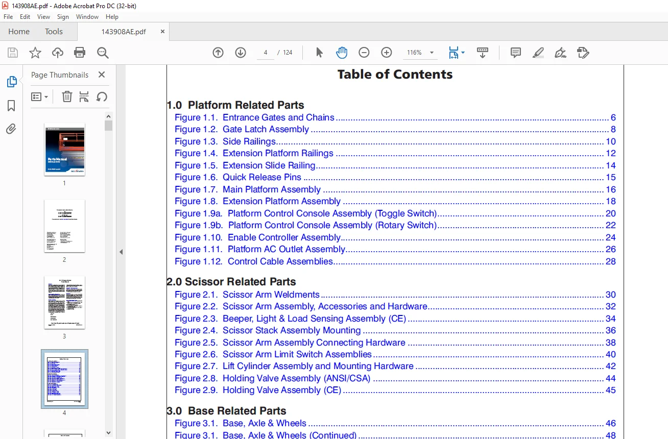
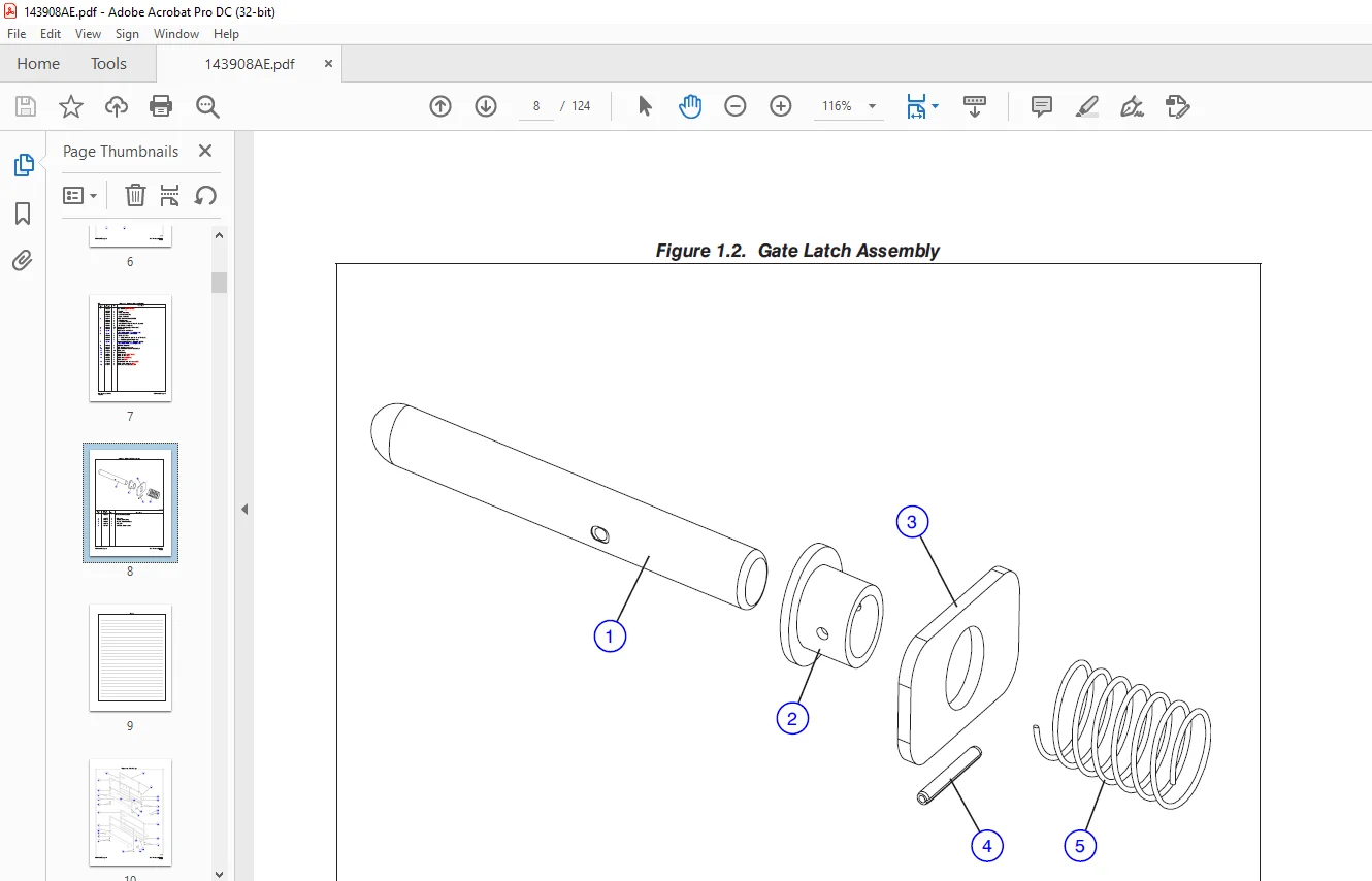
1.0  Platform Related Parts...............................................................  6
	Figure 1.1.  Entrance Gates and Chains................................................  6
	Figure 1.2.  Gate Latch Assembly......................................................  8
	Figure 1.3.  Side Railings............................................................ 10
	Figure 1.4.  Extension Platform Railings.............................................. 12
	Figure 1.5.  Extension Slide Railing.................................................. 14
	Figure 1.6.  Quick Release Pins....................................................... 15
	Figure 1.7.  Main Platform Assembly................................................... 16
	Figure 1.8.  Extension Platform Assembly.............................................. 18
	Figure 1.9a.  Platform Control Console Assembly (Toggle Switch)....................... 20
	Figure 1.9b.  Platform Control Console Assembly (Rotary Switch)....................... 22
	Figure 1.10.  Enable Controller Assembly.............................................. 24
	Figure 1.11.  Platform AC Outlet Assembly............................................. 26
	Figure 1.12.  Control Cable Assemblies................................................ 28
2.0 Scissor Related Parts................................................................. 30
	Figure 2.1.  Scissor Arm Weldments.................................................... 30
	Figure 2.2.  Scissor Arm Assembly, Accessories and Hardware........................... 32
	Figure 2.3.  Beeper, Light & Load Sensing Assembly (CE)............................... 34
	Figure 2.4.  Scissor Stack Assembly Mounting.......................................... 36
	Figure 2.5.  Scissor Arm Assembly Connecting Hardware................................. 38
	Figure 2.6.  Scissor Arm Limit Switch Assemblies...................................... 40
	Figure 2.7.  Lift Cylinder Assembly and Mounting Hardware............................. 42
	Figure 2.8.  Holding Valve Assembly (ANSI/CSA)........................................ 44
	Figure 2.9.  Holding Valve Assembly (CE).............................................. 45
3.0  Base Related Parts................................................................... 46
	Figure 3.1.  Base, Axle & Wheels...................................................... 46
	Figure 3.1.  Base, Axle & Wheels (Continued).......................................... 48
	Figure 3.2.  Pothole Protection Device................................................ 50
	Figure 3.3.  Control Module Assembly.................................................. 52
	Figure 3.4.  Tire Assembly............................................................ 54
	Figure 3.5.  Steer Mechanism.......................................................... 56
	Figure 3.6.  Steer Assembly........................................................... 58
	Figure 3.7.  Rear Axle Assembly....................................................... 59
	Figure 3.8.  Brake Cylinder Assembly.................................................. 60
	Figure 3.9.  Steer Cylinder Assembly.................................................. 61
	Figure 3.10.  Hydraulic Hose Connections.............................................. 62
	Figure 3.11.  Steering Manifold Assembly.............................................. 63
	Figure 3.12.  Base Control Console Hardware........................................... 64
	Figure 3.13.  Base Control Harness and Switches....................................... 66
4.0  Hydraulic Tray Related Parts......................................................... 68
	Figure 4.1.  Hydraulic/Electrical Tray Assembly....................................... 68
	Figure 4.2.  Main Manifold Assembly................................................... 70
	Figure 4.3.  Motor and Pump Assembly.................................................. 74
	Figure 4.4.  Emergency Lowering Manifold Assembly..................................... 76
	Figure 4.5.  Proportional Manifold Assembly........................................... 77
	Figure 4.6.  Hydraulic Tank Lid Assembly.............................................. 78
	Figure 4.7.  Hydraulic Hose Connections............................................... 79
5.0  Battery Tray Related Parts........................................................... 80
	Figure 5.1.  Battery Tray Assembly.................................................... 80
	Figure 5.2.  Battery Charger.......................................................... 86
6.0  Electrical Related Parts............................................................. 88
	Figure 6.1.  Electrical Panel and Hardware Assembly................................... 88
	Figure 6.2.  Main Manifold Harness.................................................... 90
	Figure 6.3.  Rear Manifold Harness.................................................... 92
	Figure 6.4.  Horn/Flashing Light, Tilt Switch & Holding Valve Harnesses (ANSI/CSA).... 93
	Figure 6.5.  Horn, Control Module & Holding Valve Harnesses (CE)...................... 94
	Figure 6.6.  Elevate Telematics Harness............................................... 96
	Figure 6.6.  Elevate Telematics Harness............................................... 97
7.0  Optional Equipment................................................................... 98
	Figure 7.1.  24VDC Inverter and Hardware.............................................. 98
	Figure 7.2.  Inverter Assembly........................................................100
	Figure 7.3.  Inverter Label Placement.................................................102
	Figure 7.4.  Platform Air Supply Hose.................................................103
	Figure 7.5.  Slate Grey Label Option..................................................104
	Figure 7.6.  Flashing Amber Light Option..............................................105
	Figure 7.7.  Dual Flashing Amber Light Option (Diagonal) (ANSI/CSA)...................106
	Figure 7.8.  Tool Caddy...............................................................108
	Figure 7.9.  Elevate Telematics.......................................................110
	Figure 7.10  Secondary Guarding Lift Enable Kit.......................................112
	Figure 8.1.  Label Kit................................................................113
8.0  Label Kit............................................................................113
	Figure 8.2.  Label - Platform Control Console.........................................115
	Figure 8.3.  Labels - Miscellaneous...................................................116
	Figure 8.4.  Labels - Sides...........................................................118
9.0  Fluid Table..........................................................................122
	Table 9.1.  SJ3 Scissor Fluids........................................................122
IMAGES PREVIEW OF THE MANUAL:
Questions? Email us: [email protected]
PLEASE NOTE:
- This is the SAME exact manual used by your dealers to fix your vehicle.
- The same can be yours in the next 2-3 mins as you will be directed to the download page immediately after paying for the manual.
- Any queries / doubts regarding your purchase, please feel free to contact [email protected]
S.V