
Sony CCD-FX700E Video Hi8 Handycam Service Manual – AEP UK E Australian Models
Original price was: $19.95.$12.95Current price is: $12.95.
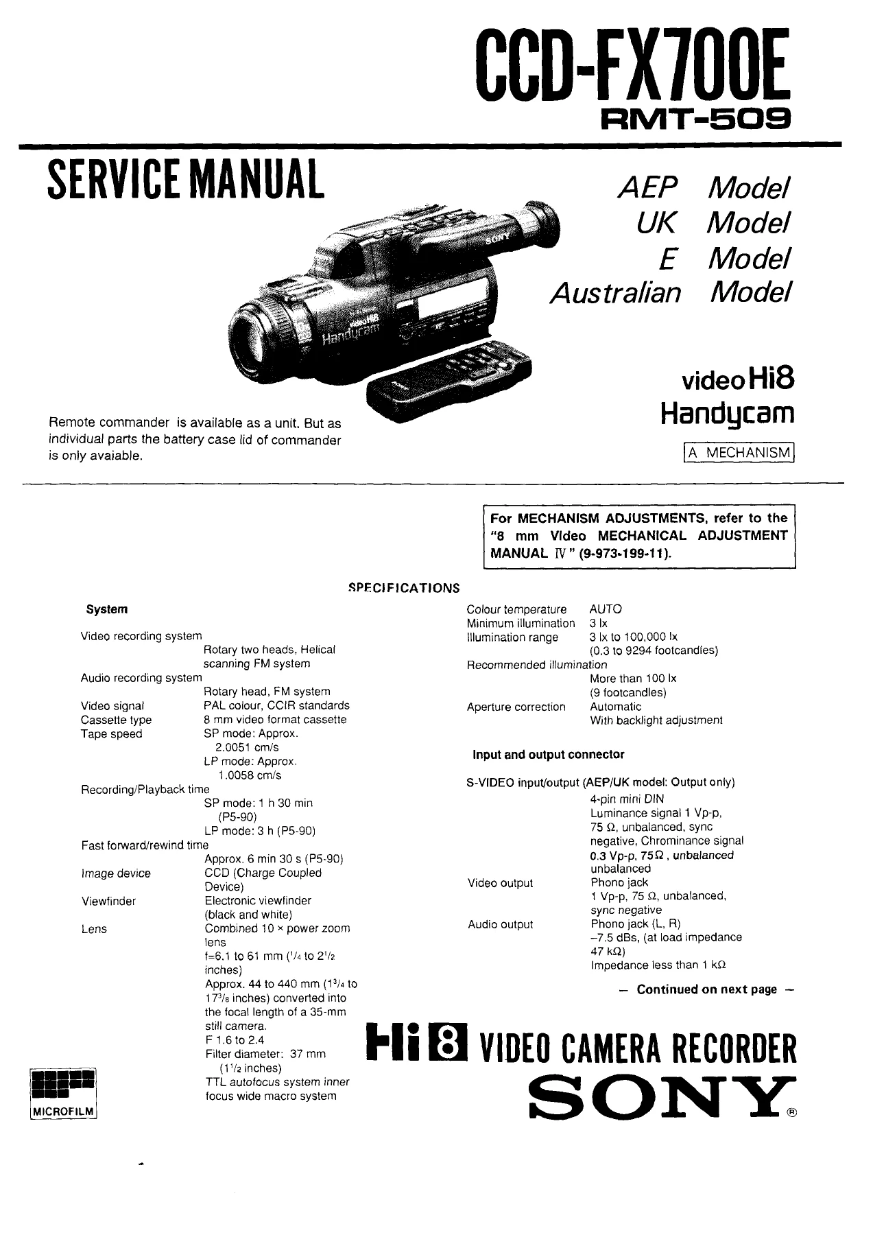
Complete service manual for the Sony CCD-FX700E Video Hi8 Handycam (RMT-509), covering AEP, UK, E, and Australian models. Includes disassembly procedures, circuit descriptions, exploded parts views, camera section adjustments, VTR section adjustments, mechanical adjustments, and board layout diagrams. Instant PDF download.
Description
Sony CCD-FX700E Video Hi8 Handycam Service Manual — AEP, UK, E & Australian Models
This is the factory service manual for the Sony CCD-FX700E Video Hi8 Handycam, also covering the RMT-509 remote commander. The document addresses four regional variants: AEP Model, UK Model, E Model, and Australian Model — all within a single comprehensive reference. Whether you are tracing a fault in the camera section, adjusting the electronic viewfinder, or working through VTR playback signal problems, the Sony CCD-FX700E Service Manual provides the structured technical depth a working technician needs.
File Details
- Manual Type: Service Manual
- Brand: Sony
- Model: CCD-FX700E (with RMT-509 Remote Commander)
- Regional Variants: AEP, UK, E, Australian
- Language: English
- Pages: 134 (PDF file pages)
- File Format: PDF
Chapters Covered
- Section 1 — General: Identifying the Parts (B-1 through B-9 diagrams, all controls and connectors labelled; wireless remote commander layout)
- Connecting the Power Sources: battery pack installation, alkaline battery case EBP-77, AC adaptor, car battery adaptor, battery life indicator
- Recording Operations: automatic adjustments, low-angle recording, tape length indicator, date and time recording
- High-Speed Shutter: shutter speed selection (1/120 to 1/4000), usage examples
- Adjusting the Exposure: EXPOSURE ON/OFF, manual exposure dial, backlight compensation
- Special Recording Features: superimpose title, colour/mode, memory functions
- Editing onto Another VTR: S-VIDEO and VIDEO connections, EDIT switch operation, DATA SCREEN superimpose
- Maintenance and Precautions: head cleaning procedure (V6-25CLH cassette method), viewfinder cleaning, moisture condensation, precautions for use abroad, colour system differences (PAL/NTSC/SECAM/PALM), tape handling
- Section 2 — Disassembly Procedures: cabinet removal, control switch block assembly removal, EVF assembly removal (VF-44 board Type A / VF-51 board Type B)
- Section 3 — Circuit Description and Block Interface: mechanism control microprocessor IC503 (CS-33 board, CXP80624A-016Q) full pin function table; system control / video-audio block interface signal table; audio matrix control signal tables for REC and PB modes
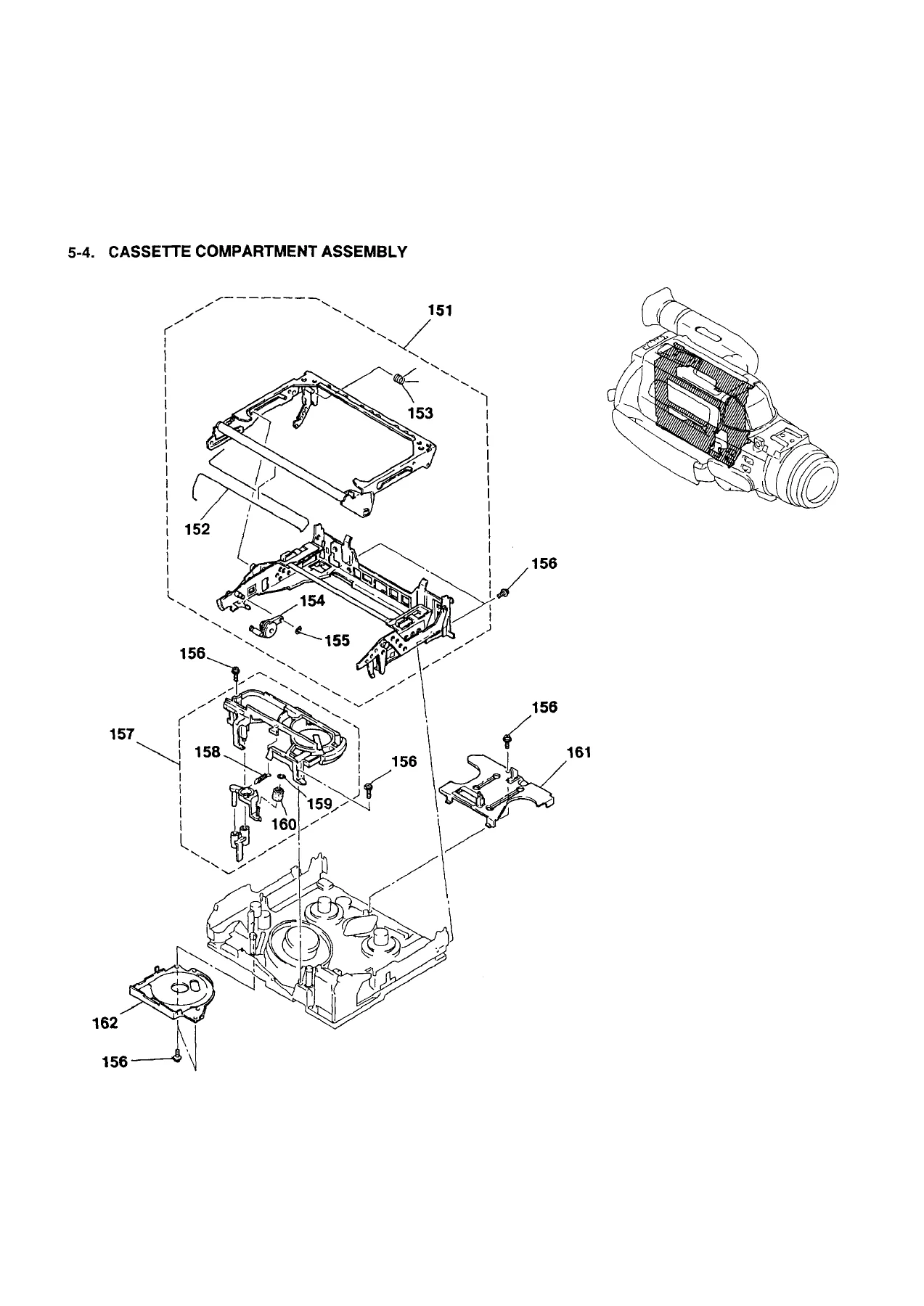
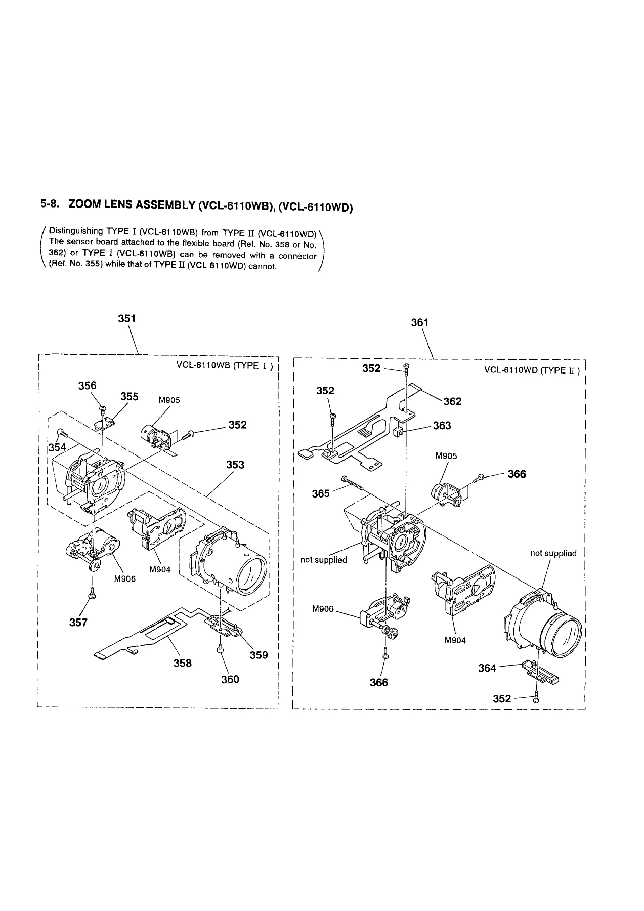
- Section 4 & 5 — Exploded Parts Views: cassette compartment assembly, mechanism chassis assembly (M901–M903), zoom lens assembly (VCL-6110WB Type I / VCL-6110WD Type II)
- Section 6 — Head Cleaning and Semiconductor Location: head clog detection during recording and playback, cleaning tape remedy, semiconductor (IC/transistor/diode) location guide for boards
- Section 7 — Camera Section Adjustments: service tools list (J-1 through J-14 with part codes); switch settings and precautions before adjustment; flange back check and white pattern adjustment procedure; Page F address list (full hexadecimal address table: FADER LEVEL, VSUB, VPGH, VREF Y, VREF C, HALL GAIN, HALL OFFSET, CORE series addresses, AWB parameters, zoom speed, AF control, AE thresholds); HALL adjustment (step-by-step with equations); Max Gain adjustment (CS-33 board); IRIS IN/OUT adjustment; EVF system adjustments — horizontal tilt (VF-44 board), centering, AFC (RV504 specified at 2.30 ±0.05 Vdc)
- Section 8 — Mechanical Section Adjustments: track shift mode setting procedure; mechanism control computer version (IC503, CXP80624A-016Q, part 8-752-842-05); mode control computer version (IC506); preparation for adjustment including RF waveform check using alignment tape WRS-1CP
- Section 9 — VTR Section Adjustments: signal connection diagrams for S-VIDEO and VIDEO input modes (with and without input/output switch); checking input signals (Y signal ~0.7Vp-p, chroma ~0.3Vp-p, burst ratio 0.30:0.66); sync AGC level adjustment (VI-113 board, address 4A, A=0.5±0.01V); IR adjustment (address 4D, residual chroma below 40mVp-p); numerous additional adjustments including playback title edge Y level (SC-33 board address 82, A=0.035±0.005V); CAM E-E output level check; REC matrix L-R adjustment (address 78, 0±5mVp-p); REC matrix L+R check
- Board Layout Diagrams: RP-138 board (component side — PB frequency characteristics trimmers RV901/RV902); VI-113 board (conductor side — IC201, IC202, IC203, IC301, FL302)
Taken together, these sections give a technician the complete picture of how the CCD-FX700E is constructed, how its circuits interact, and exactly what values to target when realigning or repairing each subsystem. The adjustment chapters in particular are unusually thorough for a compact camcorder service document, covering everything from CCD imager voltage references to audio matrix balance and EVF centering tolerance (±4%).
Specifications Reference (from Manual Cover)
The cover page carries the full published specification table for the Sony CCD-FX700E: PAL colour / CCIR video signal; rotary two-head helical scanning FM video recording; rotary head FM audio (HiFi stereo); 8 mm video format cassette; tape speed SP approx. 2.0051 cm/s / LP approx. 1.0058 cm/s; recording time SP 1h 30min / LP 3h (P5-90); CCD image device; 10× power zoom lens f=6.1–61 mm, F1.6–2.4, 37 mm filter diameter, TTL autofocus inner focus wide macro; electronic black-and-white viewfinder; minimum illumination 3 lx; S-VIDEO 4-pin mini DIN; video output 1Vp-p 75Ω phono jack; audio output –7.5 dBs at 47kΩ load impedance phono jack (L, R). These specifications appear on page 1 of the PDF and serve as the definitive reference baseline for all adjustment procedures in the document.
IMAGES PREVIEW
What This Manual Lets You Do
With the Sony CCD-FX700E Video Hi8 Handycam Service Manual in hand, a technician can correctly disassemble the camcorder to board level, interpret every signal on the mechanism control microprocessor, perform the full camera section alignment sequence using the specified jigs and filters, verify and restore VTR playback signal integrity, and adjust the EVF to factory geometry and AFC values. Every procedure references exact board designations, connector numbers, and specified values — there is no guesswork involved. For a camcorder of this complexity, working from the correct service document rather than approximation is the difference between a reliable repair and a recurring fault.
Download is instant upon payment. The PDF delivers to any device — desktop, tablet, or phone — and can be printed in full or in sections as needed. No physical shipping, no waiting.
Reviews
There are no reviews yet.