Sony Dsr20/20p RMT-DS20 Workshop Repair Manual – PDF Download
Original price was: $24.95.$19.95Current price is: $19.95.
Sony Dsr20/20p RMT-DS20 Workshop Repair Manual Download
Description
Sony Dsr20/20p RMT-DS20 Workshop Repair Manual Download
FILE DETAILS:
FILE TYPE:PDF
DOWNLOADABLE:YES
MANUAL LANGUAGE:ENGLISH
PAGES:142
DESCRIPTION:
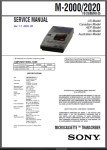
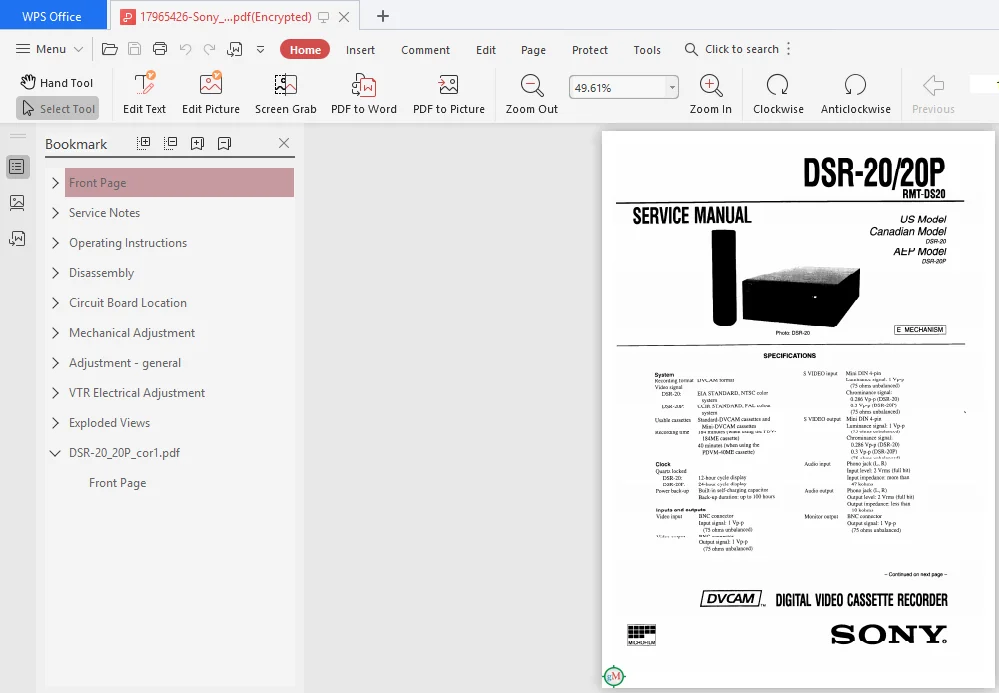
The DSR-2N20P is : l/4-inch digital video cassette recorder that uses the DVCAM digital recording format. This system actúeves stable. superb picture quality by digitaily processing video signal: that are separated into color difference signals and luminance ¡iguala (component video). The unit is equipped with a fuil-fiedged miog interface to support hybrid systems that combine conventional analºg equipment with digital equipment. The DSR—20/20P’s main features are described below.
TABLE OF CONTENTS:
- Sony Dsr20/20p RMT-DS20 Workshop Repair Manual Download
SERVICE NOTE
1. GENERAL
Features
Notes on Video Cassettes
Notes on Recording ¡Playback
Location and Function of Parts
Playback
Connections tor Playback
Settings for Playback
Playback Procedure
Playback Functions
Recording
Connections for Recording
Setting tor Recording
Recording Procedure
Connecting Other Equipment
Changing Menu Settings
Changing the SET UP MENU Settings
Menu Contents
Alarm Messages
Notes on Use
Compatibility of DVCAM and DV Format
Glossary
2. DISASSEMBLY
2-1. Removal of Upper Case
2-2. Removal of Front Panel Assembly
2-3. Removal ofVA-102 Board
2-4. Removal of Power Block and HG-1 Board
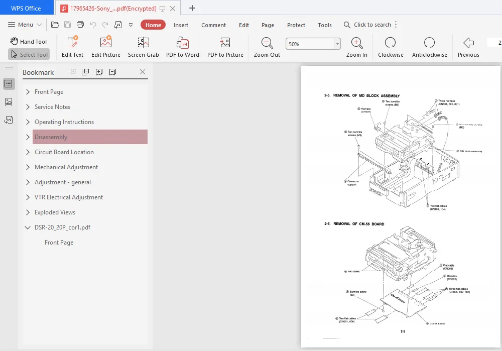
2-5. Romoval of MD Block Accombly
2-6. Removal ofCM-56 Board
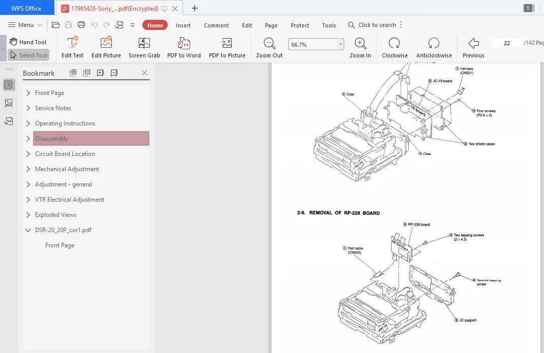
2-7. Removal of JC-19 Board
2-8. Removal of RP—228 Board
2-9. Circuit Boards Location
3. BLOCK DIAGRAMS
3-1. Overall Block Diagram (1)
3-2. Overall Block Diagram (2)
3-3. Power Block Diagram
4. PRINTED WIRING BOARDS AND
SCHEMATIC DIAGRAMS
4-1. Frame Schematic Diagram .
4-2. Printed Vlñring Boards and Schematic Diagrams
RP-228 Board
JC-19 (AD/DA Converter, Si AFC, UI,
D1 SPCON, MODE, DV in/out, Audio Core,
Digital Audio, Audio DIA, A/D Converter) Board
JC-19 (AD/DA Converter) Board
JC-19 (Just AFC, Encode) Board
JC-19(BLK-Comp) Board
J0-19 (SFY) Board
JC-19(FDF—CTLG—SPCON) Board
JC-19 (Mode) Board
JC-19 lN-51 (DV in/out) Board
JC-19 (Audio Core) Board
JC-19 (Digital Audio) Board
JC-19 (Audio DIA, A¡D Converter) Board
RE-32 Board
VA-102 (IF, Video In/Out, UVIC, DV In/Out,
Monitor Out. Audio. Hi Mlcom, RS Mícom)
Board
VA-102 (IF) Board
VA-102 (Video In) Board
VA—102 (Video Out) Board
VA-102 (UVIC & DV In/0ut) Board
VA-102 (Audio) Board
VA—102 (Hi Micom) Board
VA-102 (RS HI Micom) Board
RS-78 Board
MD-63, MD—64, MD-65 (Tape Detect),
FP-406 (Tape Sensor) Boards
HP-100 Board
CM-56 Board
FR-136 Board
U-1 Board
U-2 Board
HG-1 Board
5. ADJUSTMENTS
5-1. MECHANICAL SECTION ADJUSTMENTS
5-1.1 Information
1. How to Search Reference Pages tor Removal
2. Phase Adjustment Mark “ PH- ”
5-1-2. Preparation for Mechanical Check.
Adjustment and Maintenance
2-1. FL Block Assembly
2-2. Cassette Positions
2-3. Loading/Unioading
2-4. Manual UplDown the FL Block
2-5. Service Jigs List
5-1-3. Phase Adjustrnents
3-1. Phase Adjustment
(Loading/Unloading Driving Section)
3-2. Phase Adjustment
(SIL Cassette Selection Section)
3-3. Phase Adjustment
(Mechanism Chassis Upper Surface Parts)
5-1-4. Periodic Check and Maintenance
4—1. Cleaning of Rotary Drum Assembly
4—2. Cleaning of Tape Path System
4—3. Periodic checks
5-1—5. Mechanism Section Checks and Replacements
5—1. Tape Stopper, Motor FPO Assemny and
Elastic Connector
5—2. Dru1iiAeeiwubiy [and Drum Bueu
5—3. LM Cover, LM Worm Wheel, LM Holder and
LM Motor Assembly
5-4. TGS/4 Catcher Block Assembly,
Finch Driving Gear and TC Arm Assembly
5-5. Finch Arm Assembly, Finch Limitar and
Tension Coil Spring (Pinch)
5-6. HC Arm, HC Roller Assembly,
Finch Retainer, Finch Cam Gear and
TGS/6 Catcher Block Assemny
5—7. RL Arm and RL Link
5—8. Gooseneck Guard and Gooseneck Arm Assembly
5-9. Tension Coil Spring (T G2), Spring Adjustor,
TG2 Spring Hook, TG2 Selection Arm and Dampe
Sheet
5-10. Tension Coil Spring (TG7), Spring Adjustor and
TG? Spring Hook
5—20. FL Selection Arm, FL Relay Gear and FL Joint Arm Assemny
5—21. Rotary Switch. TC Gear and Relay Gear
5—22. GL Arm Retainer and GL Arm
5—ze. M Slider and M SilderArm
5-24. TG7 Selection Arm, TG7 Cam Gear and T Cam Gear
5-25. Main Cam, TG2 SL Arm Assembly and
Tension Coil Spring (TG2 SL)
5—26. TGS/4 Arm Block Assembly (TGS/4 Arm Assembly,
TGS/4 Limitar Spring and TGS/4 Gear) TGS/4 Base
Block Assemny (TGS/4 Base Assembly)
5-27. TG5/6 Arm Block Assembly (TG5/6 Arm Assembly,
TGS/6 Limitar Spring and TGS/6 Gear) TGS/6
Base Block Assemny (TGS/6 Base Assembly)
5-28. Reel Motor
5-29. RS Arm Assembly
5-30. RS Gear Assembly, Mic Press Spring and Mic Lever
5-31. Rack Joint Gear, Rack Holder, Mic Holder.
Rack (LC) and Rack (SC)
5—32. Plate Link Assembly .
5—33. Roller Shaft Assembly and Roller Belt
5—34. le Opener
53—35. C Door
5-36. Damper Arm and Tension Spring (DB)
5-37. Gear (A), Gear (8), and C Worm
5—38. Tension Coil Spring (HS), Tension (DB). Shift Plate
Spring and C Sioat Block Assembly
5-1-6. Adjustments and Checks
6-1. Adjustment Position
6—2. Adjustment Order
6-3. Adjustment and Checking Method
6—3-1. Reel Table Height Adjustment
8—3—2. TGZITG7 HeightAdjustment
6—3-3. FWD/BVS Position Adjustment
6-3-4. TG2/TG7 Electric Tension Regulator Adjustment
6-3-5. FWD/RVS Back Tension Adjustment
6—3-6. Adjustment Preparations and
RF Wavetorm Check
6-3-7. TrackingAdjustment
6-3-8. Tracking Check
6-3-9. CUE and REV Check
6 3 10. Rising Check
Page C Initial Value Input E
Page E Initial Value Input E
Modification of C, D, E Page Data E
Page D Address List
Page E Address List
Servo System Adjustments
Capstan FG Duty Adjustment (CM-56 Board)
Video System Adjustments
RP-228 Board Adjustments.
Recordlna Current Adiustment (RP—228 Board)
PLL fo Adjustment (RP—227 Board)
CLK Delay Adjustment (RP-228 Board)
AGO Center Level Adjustment (RP—228 Board)
AEG Adjustment (RP-228 Board)
PLL Capture Range Adjustment (RP-228 Board)
IC774 41.85 MHZ VCO Check
JC-19 Board Adjustments !
A/D Convertor Reference Voltage Adjustment 1
(JC-19 Board)
A/D Convertor Reference Voltage Adjustment 2
(JO-19 Board)
Y Signal Clamp Reference Voltage Adjustment
(JO-19 Board)
CR Signal Clamp Reference Voltage Adjustment
(JC-19 Board)
OB Signal Clamp Reference Voltage Adjustment
(JC—19 Board)
Playback Y Signal Lever Adjustment
(JC—19 Board)
Playback OR Signal Lever Adjustment
(JC—19 Board)
Playback CB Signal ever Adjustment
(JC-19 Board)
IC422 27MH2 XTAL fo Adjustment (JC—19 Board)
AFC Preliminary Adjustment (JO—19 Board)
AFC Picture Frame Adjustment (JC—19 Board)
AFC Adjustment (JO-19 Board)
VA-102 Board Adjustments
AGO Adjustment (VA—102 Board)
Analog E-E Y Signal Output Level Adjustment
(VA-102 Buard)
2. Recording System Check
3-6. Audio System Adjustments
1. Playback Level/|ndicator Check
2. EE Level Check
3. Recording/Playbact< Check (Audio LOCK Mºde)
3-7, Arrangement Diagram for Adjustment Parts
6. REPAIR PARTS LIST
6—1. Exploded Views
6—1-1. Overall Section
6-1-2. ChassisAssemblv
6-1-3. MD Block Assembly
6—1-4. FL Cassette Compartment Assemny
6-1-5. Mechanism Chassis Assembly
(Top Side View (1))
6-1-6. Mechanism Chassis Assembly
(Top Side Wew (2))
6-1—7. Mechanism Chassis Assembly
(Top Side View (S))
6 ‘I 8. Mechanism Chassis Assemny
(Bottom Side View (1))
6—1-9. Mechanism Chassis Assembly
(Bottom Side View (2))
6-2. Electrical Parts List
Hardware List
SCREENSHOT OF THE MANUAL:
SONY DSR20/20P RMT-DS20 WORKSHOP REPAIR MANUAL – PDF DOWNLOAD:
PLEASE NOTE:
⦁ This is the SAME MANUAL used by the dealerships to diagnose your vehicle
⦁ No waiting for couriers / posts as this is a PDF manual and you can download it within 2 minutes time once you make the payment.
⦁ Your payment is all safe and the delivery of the manual is INSTANT – You will be taken to the DOWNLOAD PAGE.
⦁ So have no hesitations whatsoever and write to us about any queries you may have : heydownloadss @gmail.com