Sony DVP-CX995V 400-Disc DVD CD Changer Service Manual PDF Download
Original price was: $65.00.$13.95Current price is: $13.95.
Complete Sony DVP-CX995V 400-disc mega CD/DVD changer service manual with disassembly procedures, circuit schematics, test mode instructions, optical pickup adjustments, parts list, exploded views, and troubleshooting for CDM62-DVBU65 mechanism. Includes HDMI, SACD, Dolby Digital, and DTS support.
Description
Sony DVP-CX995V 400-Disc DVD CD Changer Service Manual PDF Download
DESCRIPTION:
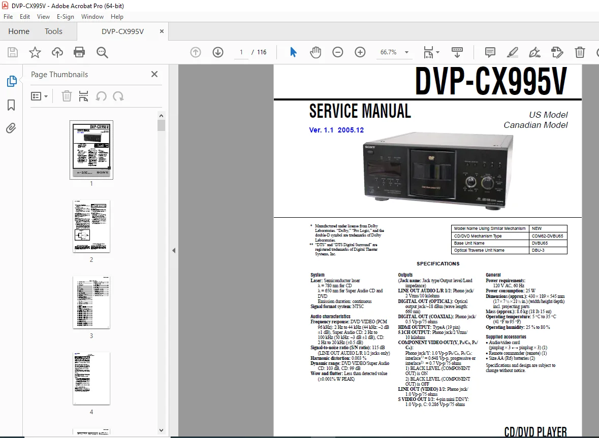
This comprehensive Sony DVP-CX995V service manual (Ver. 1.1 2005.12, Publication 9-879-772-02) provides complete factory technical documentation for servicing and repairing the Sony DVP-CX995V 400-disc mega CD/DVD changer. Essential for professional audio/video technicians, consumer electronics repair specialists, and home theater service professionals.
Product Overview:
The Sony DVP-CX995V is a premium 400-disc carousel CD/DVD/SACD player featuring advanced playback capabilities and multiple output options. This legendary mega changer is known for its massive disc capacity and versatile format support.
Key Features:
- 400-Disc Capacity – Mega storage for extensive media libraries
- Multi-Format Playback: DVD-Video, CD, Super Audio CD (SACD), DVD±R/RW, CD-R/RW
- High-Definition Output: HDMI output with 1080p upscaling capability
- Audio Technologies: Dolby Digital, Dolby Pro Logic, DTS Digital Surround
- Component Video Output: Progressive scan (Y, Pb/Cb, Pr/Cr)
- Digital Audio Outputs: Optical and coaxial SPDIF
- 5.1 Channel Analog Outputs for multi-channel SACD playback
Mechanism Details:
CD/DVD Mechanism Type: CDM62-DVBU65
- Base Unit: DVBU65
- Optical Traverse Unit: DBU-3
- Laser Specifications:
- λ = 780 nm for CD playback
- λ = 650 nm for Super Audio CD and DVD
- Emission duration: continuous
- Semiconductor laser diode
TABLE OF CONTENTS
SECTION 1 – SERVICING NOTES (Pages 4-8)
- Notes on handling the optical pick-up block or base unit
- Laser diode electrostatic protection procedures
- ESD (Electrostatic Discharge) precautions
- Flexible circuit board handling
- Notes on laser diode emission check – safety distance requirements
- Notes on replacement of the MB Board:
- Flash memory (IC202) handling and exchange procedures
- Adjustment value initialization
- Memory check and initialization procedures
- Note on handling the AV Board (A-1126-999-A)
- IC600 physical destruction requirements when disposing
- Chip component replacement guidelines
- Flexible circuit board repairing techniques
- Soldering iron temperature specifications (270°C)
- Safety check-out procedures
- Leakage test requirements (0.5 mA maximum)
- Three approved testing methods
- Commercial leakage testers
- AC milliammeter testing
- Voltage drop measurement
- Unleaded solder handling notes
- Lead-free mark (LF) identification
- Higher melting temperature (40°C increase)
- Soldering iron settings (350°C recommended)
- Viscosity characteristics
- Safety-related component warning (marked with 0 symbol)
SECTION 2 – GENERAL (Page 9)
- Model identification
- US and Canadian model specifications
- General overview and features
SECTION 3 – DISASSEMBLY (Pages 10-21)
Complete step-by-step disassembly procedures:
- 3-1. Disassembly Flow – Overall sequence diagram
- 3-2. Case removal
- 3-3. MB Board removal and installation
- 3-4. AV Board removal procedures
- 3-5. Bracket (L)/(R) removal
- 3-6. Front Panel Section disassembly
- 3-7. Cover (PT)/(CDM) removal
- 3-8. DVBU65 Assembly (DVD mechanism)
- 3-9. Switching Regulator removal
- 3-10. Table (400) Assembly – Carousel mechanism
- 3-11. Door Assembly, Base (Door) Assembly
- 3-12. DC Motor (Door) (M603) removal
- 3-13. Holder (Table Sensor 400) removal
- 3-14. D. SENS OUT Board, D. SENS IN Board – Disc sensors
- 3-15. Pop-up (400) Assembly – Disc loading mechanism
- 3-16. DOOR SW Board removal
- 3-17. LOCK SW Board, LOADING SW Board removal
- 3-18. CD/DVD Mechanism Deck Block (CDM62-DVBU65) complete disassembly
- 3-19. Motor (400) Assembly:
- Loading Motor (M602)
- Table Motor (M601)
- LOADING MOTOR Board
- 3-20. Optical Traverse Unit (DBU-3) removal and handling
SECTION 4 – TEST MODE (Pages 22-31)
Comprehensive test mode operations:
- Test Mode entry procedure using remote commander
- Key sequence: TOP MENU > CLEAR > I/1 (standby status)
- “DIAG START” display on fluorescent indicator
- Test Mode Menu navigation
- Drive Manual Operation:
- Disc loading/unloading tests
- Table rotation testing
- Sensor verification
- Memory Check and initialization
- Drive Auto Adjustment procedures
- Focus offset adjustment
- Tracking offset adjustment
- Laser power calibration
- Servo diagnostics
- Audio/Video output testing
- Button and switch function tests
- Display diagnostics
- Remote control command verification
- Error code reference
SECTION 5 – MECHANICAL ADJUSTMENTS (Page 32)
- Disc loading mechanism alignment
- Table (carousel) rotation adjustment
- Door operation timing
- Pop-up mechanism calibration
- Sensor positioning
- Motor speed adjustments
- Mechanical play reduction
SECTION 6 – ELECTRICAL ADJUSTMENTS (Pages 33-37)
- Focus offset adjustment procedures
- Tracking gain adjustment
- RF signal level optimization
- Laser power calibration
- Servo loop adjustments
- Audio output level calibration
- Video output alignment
- Digital output verification
SECTION 7 – DIAGRAMS (Pages 38-89)
Complete technical diagrams:
Block Diagrams:
- 7-1. Block Diagram – SERVO Section (Page 38)
- Focus servo control
- Tracking servo control
- Spindle motor control
- Sled motor control
- 7-2. Block Diagram – AUDIO Section (Page 39)
- DAC (Digital-to-Analog Converter) circuits
- Dolby Digital decoder
- DTS decoder
- SACD audio processing
- Multi-channel output routing
- 7-3. Block Diagram – VIDEO Section (Page 40)
- Video decoder circuits
- Component video processing
- S-Video and composite output
- HDMI interface
- 7-4. Block Diagram – PANEL, TABLE, POWER SUPPLY Section (Page 41)
- Switching regulator
- Power distribution
- Control panel interface
- Carousel control system
Printed Wiring Boards & Schematics:
- 7-5. RF TRANSLATION Board layout (Page 43)
- 7-6. MB Board (Side A) component layout (Page 44)
- 7-7. MB Board (Side B) conductor traces (Page 45)
- 7-8 to 7-14. MB Section Schematics (1/7 through 7/7) (Pages 46-52)
- Complete main board circuit diagrams
- Microprocessor circuits
- Memory circuits (Flash IC202)
- Interface circuits
- Power supply circuits
- 7-15 to 7-19. AV Board Schematics (1/5 through 5/5) (Pages 53-57)
- Audio processing circuits
- Video processing circuits
- DAC circuits
- Output buffers
- IC600 critical component
- 7-20. AV Board – Component Side (Page 58)
- 7-21. AV Board – Conductor Side (Page 59)
- 7-22. TABLE Section boards (Page 60)
- 7-23. TABLE Section schematic (Page 61)
- 7-24. DRIVER Board layout (Page 62)
- 7-25. DRIVER Board schematic (Page 63)
- 7-26. PANEL-L Board layout (Page 64)
- 7-27. PANEL-L Board schematic (Page 65)
- 7-28. PANEL-R Section boards (Page 66)
- 7-29. PANEL-R Section schematic (Page 67)
SECTION 8 – EXPLODED VIEWS (Pages 90-100)
Detailed mechanical assembly diagrams:
- 8-1. Overall Section (Page 90) – Complete unit assembly
- 8-2. Front Panel Section (Page 91)
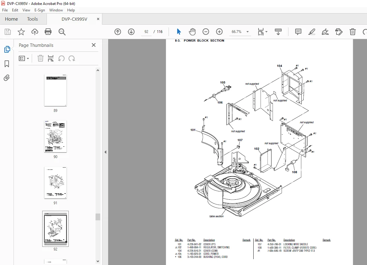
- 8-3. Power Block Section (Page 92)
- 8-4. Table Section (Page 93) – 400-disc carousel mechanism
- 8-5. Chassis Section (Page 94)
- 8-6. Base (Door) Section (Page 95)
- 8-7. CD/DVD Mechanism Deck Section-1 (Pop-up Block) (Page 96)
- 8-8. CD/DVD Mechanism Deck Section-2 (Pulley Block) (Page 97)
- 8-9. CD/DVD Mechanism Deck Section-3 (Lever, Holder Block) (Page 98)
- 8-10. CD/DVD Mechanism Deck Section-4 (Gear, Motor Block) (Page 99)
- 8-11. Base Unit Section (DVBU65) (Page 100) – DVD mechanism base
SECTION 9 – ELECTRICAL PARTS LIST (Pages 101-116)
Complete parts catalog with part numbers:
- Resistors, capacitors, diodes, transistors
- Integrated circuits (ICs)
- Connectors and switches
- Motors and mechanical components
- Optical pick-up components
- Safety-critical components marked
- Boards and assemblies
- Cables and harnesses
- Ordering information
SPECIFICATIONS
System:
- Signal Format: NTSC
- Laser Type: Semiconductor laser
- λ = 780 nm for CD
- λ = 650 nm for Super Audio CD and DVD
- Emission: Continuous
Outputs:
- LINE OUT AUDIO L/R 1/2: Phono jack, 2 Vrms, 10 kilohms
- DIGITAL OUT (OPTICAL): –18 dBm (wavelength: 660 nm)
- DIGITAL OUT (COAXIAL): 0.5 Vp-p, 75 ohms
- HDMI OUTPUT: Type A (19 pin)
- 5.1CH OUTPUT: Phono jack, 2 Vrms, 10 kilohms
- COMPONENT VIDEO OUT (Y, PB/CB, PR/CR): Phono jack
- Y: 1.0 Vp-p
- PB/CB, PR/CR: Interlace = 0.648 Vp-p, Progressive = 0.7 Vp-p
- 75 ohms impedance
- LINE OUT (VIDEO) 1/2: Phono jack, 1.0 Vp-p, 75 ohms
- S VIDEO OUT 1/2: 4-pin mini DIN, Y: 1.0 Vp-p, C: 0.286 Vp-p, 75 ohms
Audio Characteristics:
- Frequency Response:
- DVD VIDEO (PCM 96 kHz): 2 Hz to 44 kHz
- Super Audio CD: 2 Hz to 100 kHz
- CD: 2 Hz to 20 kHz (±0.5 dB)
- Signal-to-Noise Ratio: 115 dB (LINE OUT jacks)
- Harmonic Distortion: 0.003%
- Dynamic Range:
- DVD VIDEO/Super Audio CD: 103 dB
- CD: 99 dB
- Wow and Flutter: Less than detected value (±0.001% W PEAK)
General:
- Power Requirements: 120V AC, 60 Hz
- Power Consumption: 25W
- Dimensions: 430 × 189 × 545 mm (17 × 7½ × 21½ in.) W/H/D including projecting parts
- Mass: 8.6 kg (18 lb 15 oz)
- Operating Temperature: 5°C to 35°C (41°F to 95°F)
- Operating Humidity: 25% to 80%
Supplied Accessories:
- Audio/video cord (pinplug × 3 to pinplug × 3) (1)
- Remote commander RM-ASP001 (1)
- Size AA (R6) batteries (2)
KEY FEATURES OF THIS SERVICE MANUAL:
✓ Official Sony factory service documentation ✓ Complete 400-disc carousel mechanism disassembly and repair ✓ Detailed CDM62-DVBU65 DVD mechanism service procedures ✓ Optical pick-up (DBU-3) adjustment and alignment ✓ Comprehensive circuit schematics for all boards ✓ Test mode procedures for diagnostics and calibration ✓ Flash memory (IC202) replacement procedures ✓ Complete parts list with Sony part numbers ✓ Exploded views with mechanical assembly details ✓ Electrical adjustments for focus, tracking, and laser power ✓ Safety precautions for laser diode servicing ✓ Lead-free solder handling guidelines ✓ Professional Sony service standards
Applications:
This Sony DVP-CX995V service manual is essential for:
- Authorized Sony service centers
- Independent consumer electronics repair shops
- Home theater installation professionals
- Audio/video service technicians
- Professional calibration specialists
- Technical training schools
Ideal For:
- Professional A/V technicians
- Sony certified service engineers
- Consumer electronics repair specialists
- Home theater installers
- Technical students and apprentices
- Mobile electronics repair services
- Multi-disc changer specialists
This comprehensive factory service manual provides the complete technical knowledge required to properly diagnose, repair, and maintain the Sony DVP-CX995V 400-disc mega changer, ensuring optimal performance of this premium home theater component.
FILE DETAILS:
| Specification | Details |
|---|---|
| Manual Title | DVP-CX995V Service Manual |
| Model Covered | Sony DVP-CX995V 400-Disc CD/DVD/SACD Player |
| Model Regions | US Model, Canadian Model |
| Mechanism Type | CDM62-DVBU65 (Base Unit: DVBU65, Optical: DBU-3) |
| Version | Ver. 1.1 (December 2005) |
| Publication Number | 9-879-772-02 |
| Publisher | Sony Corporation – Home Audio Division / Sony Engineering Corporation |
| Publication Date | December 2005 |
| Total Pages | 116 pages |
| File Size | 8.8 MB |
| PDF Quality | High-quality original factory documentation with circuit schematics and exploded diagrams |
| Language | English |
| File Format | Searchable PDF (A4 size, optimized) |
| Technologies | Dolby Digital, Dolby Pro Logic, DTS Digital Surround, SACD, HDMI |