Sony PCG-FX220 FX220K FX240 FX240K PCG-FX250 FX250K FX270 FX270K NOTEBOOK COMPUTER SERVICE MANUAL – PDF DOWNLOAD
Original price was: $80.00.$17.95Current price is: $17.95.
Sony PCG-FX220 FX220K FX240 FX240K PCG-FX250 FX250K FX270 FX270K NOTEBOOK COMPUTER SERVICE MANUAL – PDF DOWNLOAD
9-872-227-11
Description
Sony PCG-FX220 FX220K FX240 FX240K PCG-FX250 FX250K FX270 FX270K NOTEBOOK COMPUTER SERVICE MANUAL – PDF DOWNLOAD
Information in this document is subject to change without notice.
Sony and VAIO me trademarks of Sony. Intel logo and Intel Inside operating and the service instructions. logo are registered trademarks of Intel Corporation. Pentium MM}! is a trademark of Intel Corporation. Microsoft, MS-DOS, Windows,
All other trademarks are trademarks or registered trademarks of their respective owners.
CAUTION:
Danger of explosion if battery is incorrectly replaced. the Windows 95 andWindows 9810go are trademarks of Microsoft Replace only with the same or equitalent type recommended by Corporation. the manufacturer. Discard used batteries according to the manufacturer‘s instructions.
Other trademarks and trade names may be
CAUTION:
The battery pack used in this device may present a fire used in this document to refer to the entitles claiming the marks ad or chemical btmr hazard if mistreated Do not disassemble, heat names or their produces. Sony Corporation disclaims any proprietary above 100°C 012’?) or incinerate. interest in trademarks and trade names other than its own. Dispose of used battery promptly. Keep away from children.
CAUTION:
Changing the back up battery. ‘ Overcharging, short circuiting, reverse charging, multilation or incineration of the cells must be avoided to prevent one ormore of the following occtnratces; release of tor-tic materials, release of hydrogen anchor oxygen gas, rise in surface temperature. – If a cell has leaked or vented, it should be replaced immediately while avoiding to touch it without any protection
Service and Inspection Precautions|
1. Obey precautionary markings and instructions Labels and stamps on the cabinet, chassis, and components identify areas requiring special precautions. Be sure to observe these precautions, as well as all precautions listed in the operating manual and other associated documents.
2. Use designated parts only The sets components possess important safety characteristics, such as noncombustibility and the ability to tolerate large voltages. Be sure that replacement parts possess the same safety characteristics as the originals. Also remember that the A made which appears in circuit diagrams and parts lists, denotes components that have particularly important safety functions; be extra sure to use only the designated components.
3. Always follow the original design when mounting parts and routing wires The original layout includes various safety features, such as inclusion of insulating materials (tubes and tape) and the mounting of parts above the printer board. In addition internal Wiring has been routed and clamped so as to keep it away fiom hot or high-voltage parts. When mounting parts or routing wires, therefore, be sure to duplicate the original layout.
4. Inspect after completing service After servicing, inspect to make sure that all screws, components, and wiring have been returned to their original condition Also check the area around the repair location to ensure that repair work has caused no damage, and confirm safety.
5. When replacing chip components… Never reuse components. Also remember that the negative side of tantalum capacitors is easily |damaged by heat.
6. When handling flexible print boards… – The temperature of the soldaing—iron tip should be about 270C. – Do not apply the tip more than three times to the same pattern. – Handle patterns with care; never apply force.
Sony PCG-FX220 FX220K FX240 FX240K PCG-FX250 FX250K FX270 FX270K NOTEBOOK COMPUTER SERVICE MANUAL – PDF DOWNLOAD
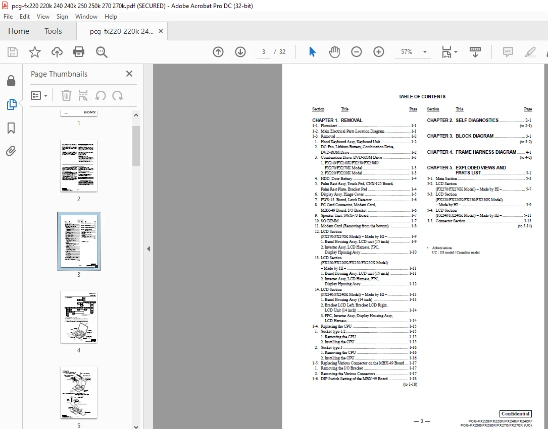
Cover…………………………………………………………………….. 1
TABLE OF CONTENTS………………………………………………………….. 3
CHAPTER 1. REMOVAL…………………………………………………………. 4
1-1. Flowchart…………………………………………………………. 4
1-2. Main Electrical Parts Location Diagram……………………………….. 4
1-3. Removal…………………………………………………………… 5
1. Hood Keyboard Assy, Keyboard Unit………………………………….. 5
2. DC-Fan, Lithium Battery, Combination Drive, DVD-ROM Drive…………….. 5
3. Combination Drive, DVD-ROM Drive…………………………………… 6
1. FX240/FX240K/FX250/FX250K/FX270/FX270K Model…………………….. 6
2. FX220/FX220K Model……………………………………………. 6
4. HDD, Door Battery………………………………………………… 7
5. Palm Rest Assy, Touch Pad, CNX-125 Board, Palm Rest Plate, Bracket Pad…. 7
6. Display Assy, Hinge Cover…………………………………………. 8
7. PWS-13 Board, Latch Detector………………………………………. 9
8. PC Card Connector, Modem Card, MBX-49 Board, I/O Bracket……………… 9
9. Speaker Unit, SWX-73 Board…………………………………………10
10. SO-DIMM…………………………………………………………10
11. Modem Card (Removing from the bottom)………………………………11
12. LCD Section (FX270/FX270K Model) – Made by HI –……………………..12
1. Bezel Housing Assy, LCD unit (15 inch)…………………………..12
2. Inverter Assy, LCD Harness, FPC, Display Hpusing Assy……………..13
13. LCD Section (FX220/FX220K/FX250/FX250K Model) – Made by HI –………….14
1. Bezel Housing Assy, LCD unit (15 inch)…………………………..14
2. Inverter Assy, LCD Harness, FPC, Display Hpusing Assy……………..15
14. LCD Section (FX240/FX240K Model) – Made by HI –……………………..16
1. Bezel Housing Assy (14 inch)……………………………………16
2. Bracket LCD Left, Bracket LCD Right, LCD Unit (14 inch)……………17
3. FPC, Inverter Assy, Display Housing Assy, LCD Harness……………..17
1-4. Replacing the CPU…………………………………………………..18
1. Socket type 1, 2………………………………………………….18
1. Removing the CPU………………………………………………18
2. Installing the CPU…………………………………………….18
2. Socket type 3…………………………………………………….19
1. Removing the CPU………………………………………………19
2. Installing the CPU…………………………………………….19
1-5. Replacing Various Connectors on the MBX-49 Board……………………….20
1. Removing the I/O Bracket…………………………………………..20
2. Removing the Various Connectors…………………………………….20
1-6. DIP Switch Setting of the MBX-49 Board………………………………..21
CHAPTER 2. SELF DIAGNOSTICS………………………………………………….22
CHAPTER 3. BLOCK DIAGRAM…………………………………………………….23
CHAPTER 4. FRAME HARNESS DIAGRAM……………………………………………..24
CHAPTER 5. EXPLODED VIEWS AND PARTS LIST………………………………………25
5-1. Main Section……………………………………………………….26
5-2. LCD Section (FX270/FX270K Model) – Made by HI –………………………..28
5-3. LCD Section (FX220/FX220K/FX250/FX250K Model) – Made by HI –…………….29
5-4. LCD Section (FX240/FX240K Model) – Made by HI –………………………..30
5-5. Connector Section…………………………………………………..31
- This is the SAME MANUAL used by the dealerships to diagnose your vehicle
- No waiting for couriers / posts as this is a PDF manual and you can download it within 2 minutes time once you make the payment.
- Your payment is all safe and the delivery of the manual is INSTANT – You will be taken to the DOWNLOAD PAGE.
- So have no hesitations whatsoever and write to us about any queries you may have : heydownloadss @gmail.com
S.M