Spacelabs 91387 Service Manual PDF Ultraview SL Patient Monitor PDF
Original price was: $75.00.$19.95Current price is: $19.95.
Official Spacelabs Medical service manual for 91387 series patient monitors including 91387-27, 91387-28 bedside monitors and 91387-38 central monitor with Ultraview SL technology. This comprehensive 116-page technical manual (Part Number 070-1159-00 Rev. F, March 2007) covers installation, setup, theory of operation, preventive maintenance, troubleshooting, diagnostics, and repair procedures for qualified biomedical technicians servicing these advanced multi-parameter patient monitoring systems used in critical care environments.
Description
Spacelabs 91387 Service Manual PDF Ultraview SL Patient Monitor 91387-27 91387-28 – PDF DOWNLOAD
DESCRIPTION
This is the official Spacelabs Medical Service Manual for 91387 Series Patient Monitors (Part Number 070-1159-00 Revision F, March 14, 2007), covering the 91387-27 and 91387-28 bedside monitors and the 91387-38 central monitor with Ultraview SL technology. This comprehensive 116-page technical manual provides complete service information for qualified biomedical engineers and technicians to install, configure, maintain, troubleshoot, and repair these advanced multi-parameter patient monitoring systems used in intensive care units, emergency departments, and critical care environments worldwide.
Product Overview
Spacelabs Medical 91387 Series Patient Monitors:
The 91387 series represents advanced patient monitoring solutions combining Spacelabs Medical module capability with enhanced expandability and networking features. These monitors support comprehensive physiological parameter monitoring with real-time waveform display, alarm management, and network connectivity for integrated patient surveillance across healthcare facilities.
Key Applications:
- Intensive Care Units (ICU)
- Cardiac Care Units (CCU)
- Emergency departments
- Post-anesthesia care units (PACU)
- Progressive care units
- Operating rooms
- Neonatal intensive care units (NICU)
- Pediatric intensive care
- Telemetry monitoring
- Central monitoring stations
Models Covered
Bedside Monitors:
- 91387-27 – Bedside patient monitor with integrated module slots
- 91387-28 – Bedside patient monitor with advanced features
Central Monitor:
- 91387-38 – Central monitoring station for surveillance of multiple patients
All models feature Ultraview SL technology and are fully compatible with Spacelabs Medical parameter modules.
Key Features and Technologies
Ultraview SL Technology:
- Advanced display capabilities
- Intuitive user interface
- Real-time waveform display
- Comprehensive alarm management
- Trend data storage and display
- Network connectivity
Modular Design:
- Left side plug-in support for two single-high or one double-high module
- Expandable via 90491/90499 module housing
- Maximum 26 parameters supported
- Three times the number of waveforms purchased
- Hot-swappable parameter modules
Network Capabilities:
- Ethernet 10/100BaseT connectivity
- Remote View feature
- Alarm Watch functionality
- DNA (Data Network Architecture) integration
- Patient data transfer
- Central station connectivity
Display Options:
- External flat-panel LCD display
- External CRT display compatibility
- Touchscreen support
- Video output for external displays
- Multiple display zones
Technical Specifications
Physical Dimensions:
- Main enclosure with integrated module slots
- Compact bedside design
- Mountable configurations available
- External display requirements
Electrical Specifications:
Power Requirements:
- External DC power supply (18V)
- AC power supply: 119-0479-00
- Internal DC-to-DC converter
- Multiple voltage rails generated internally
Battery Backup:
- Nickel Metal Hydride (NiMH) battery packs
- 12 VDC, 0.65 Ahr, 10 AAA cells
- Typical life cycle: 500 cycles
- Runtime: Up to 3 minutes (maintains critical data)
- Charge time: 8 hours (full charge)
- UPS +5V supply maintenance
- Rear panel battery access door
Environmental Requirements:
- Operating temperature specifications
- Storage temperature specifications
- Humidity specifications
- Altitude specifications
- Ventilation requirements
Regulatory Approvals:
- IEC 60601-1 medical electrical equipment safety
- Electromagnetic compatibility (EMC) compliance
- Defibrillator-proof applied parts
- Type CF applied parts
- FDA clearance (Rx Only device)
- CE marking
- International safety standards
Monitor Options
Available Configurations:
- Two integrated module slots (single-high or double-high)
- Additional modules via 90491/90499 module housing
- Flexport system interface
- Gas analyzer integration
- Perioperative option
- Various display sizes
Parameter Modules Supported:
- ECG/RESP
- SpO2
- NIBP (Non-Invasive Blood Pressure)
- IBP (Invasive Blood Pressure)
- Temperature
- Cardiac Output
- Multi-Gas
- Capnography (EtCO2)
- And other Spacelabs Medical modules
Comprehensive Manual Contents
DOCUMENT INFORMATION:
- Part Number: 070-1159-00
- Revision: F
- Publication Date: March 14, 2007
- Creator: FrameMaker 7.0
- Pages: 116 pages
- Copyright: ©2007 Spacelabs Medical, Inc.
CORPORATE OFFICES:
- Spacelabs Medical, Inc., Issaquah, WA, USA
- Authorized EC Representative: Spacelabs Healthcare, Ltd., UK
COMPLETE TABLE OF CONTENTS
CHAPTER 1: INTRODUCTION (Pages 1-1 to 1-5)
Overview:
- Manual purpose and scope
- User qualifications
- Safety warnings and cautions
- Product description
- System capabilities
Physical Dimensions:
- Main enclosure dimensions
- Weight specifications
- Mounting footprint
- Clearance requirements
Electrical Specifications:
- Power input requirements
- Power consumption
- Battery specifications
- Voltage outputs
- Current ratings
Environmental Requirements:
- Operating temperature range
- Storage temperature range
- Relative humidity specifications
- Atmospheric pressure range
- Ventilation needs
Regulatory Approvals:
- Agency certifications
- Safety standards compliance
- EMC compliance
- International approvals
Monitor Options:
- Available configurations
- Optional accessories
- Module compatibility
- Expansion capabilities
Displays:
- External display requirements
- Touchscreen specifications
- Video output capabilities
- Display resolution specifications
CHAPTER 2: SETUP (Pages 2-1 to 2-35)
Unpacking the Monitor:
- Shipping container contents
- Inventory checklist
- Accessory verification
- Damage inspection
- ESD precautions
- Component handling
Assembling the Monitor:
Batteries:
- NiMH battery specifications (12 VDC, 0.65 Ahr)
- Battery location and access
- Installation procedures
- Charging requirements (8 hours)
- Battery warnings and cautions
- Battery disposal guidelines
Connections:
- Rear panel connector layout
- J1 – Audio output (1/8″ phone jack)
- J2 – Nurse call (1/8″ phone jack)
- J3 – Alarm relay output (DB15HD female)
- J5A – Serial port 1 (DB9 female)
- J5B – Video output 1 (DB15HD female)
- J6 – Serial port 2/External touchscreen (DB9 female)
- J7 – Mouse and keyboard USB ports
- J8 – Ethernet 10/100BaseT (RJ45)
- J9 – SDLC/power output
- J10 – High-level analog output
- P1 – DC power input
- SW1 – Power ON/OFF switch
- SW2 – SDLC terminator
- Equipotential terminal
- Backup battery cover
Cabling:
Cables and Adapters (Complete Part Numbers):
- 012-0847-00 – Monitor to Alarm cable
- 012-0395-00 – Touchscreen cable, DB9, 6 feet
- 175-0951-00/01/02/03 – Ethernet cables (3′, 6′, 12′, 20′)
- 012-0593-00 – Video cable, 6 feet
- 012-0391-02/04/08/10 – Monitor to Module Housing cables (2′, 4′, 8′, 10′)
- 012-0555-00 – Flexport cable with power
- 012-0595-00 – Audio cable, 6 feet
Maximum Cable Lengths:
- SDLC cable: 40 feet maximum (12.2 m)
- Video cable: 100 feet maximum (30.5 m)
- Ethernet cable: 328 feet maximum (100 m)
SDLC External Devices:
- External device connection procedures
- Flexport interface installation
- Multiple module housing daisy-chaining
- Proper connection points
- T-cable usage (up to 3 Flexports)
SDLC Bus Termination:
- Terminator switch settings
- Terminated vs. non-terminated positions
- Switch configuration rules
- External terminator requirements
- Proper bus termination procedures
Module Housing DC Power Requirements:
- Power supply capacity
- 90499 module housing power
- Flexport power requirements
- 90469 printer power
- Maximum devices per power supply
Alarm Relay:
- J3 connector pinouts
- Pin 1 – Alarm 0 Common
- Pin 2 – Alarm 0 Normally Closed (high priority)
- Pin 3 – Alarm 0 Normally Open
- Pin 4, 8, 10, 11 – GND
- Pin 5 – Alarm 1 Normally Closed (medium priority)
- Pin 6 – Alarm 1 Normally Open
- Pin 7 – Alarm 1 Common
- Pin 9 – +12V, 140 mA
- Pin 12 – Alarm 2 Normally Open (low priority)
- Pin 13 – Alarm 2 Common
- Pin 14 – Alarm 2 Normally Closed
- Contact ratings: 250 mA, 28 V AC/DC maximum
- Circuit diagrams for each alarm function
Pre-Installation Testing:
- Pre-connection verification
- Component testing
- Cable continuity checks
Mounting Options:
- Wall mount configurations
- Cart mounting
- Pole mounting
- Desktop placement
- Mounting hardware specifications
Network Installation:
- Ethernet connection setup
- IP address configuration
- Subnet configuration
- DNS settings
- Network verification
Power-On Test:
- Initial power-up procedures
- Self-test verification
- Display initialization
- Module detection
- System status verification
Configuring the Monitor:
- BIOMED directory access
- Privileged access levels
- Configuration menus
- Monitor ID assignment
- Monitor name setup
- Subnet name configuration
- Network parameters
- Alarm settings
- Display preferences
- Audio preferences
- Time and date setting
- Drug library configuration
- Minimum volume lock
- Automatic Alarm Watch (Central Monitors):
- AUTO ALARM WATCH ON/OFF
- AUTO ALARM WATCH ACCESS ENABLE/DISABLE
- Automatic bedside monitor watching
- Zone assignment features
- System information display
- Parameter configuration (central monitors)
- Define Patient Identifier (PI) String:
- PI string configuration
- General items
- Patient name items
- Delimiter selection
- Transfer PI configuration to multiple monitors
- START/END CASE OPTIONS:
- Perioperative option configuration
- Case purge settings
- Restart state configuration
- Reset monitor procedures
CHAPTER 3: THEORY (Pages 3-1 to 3-16)
Overview:
- System architecture
- Major component interaction
- Signal flow
- Data processing
Major System Components:
Main Enclosure:
- CPU PCBA integration
- Interconnect PCBA
- Power Supply PCBA
- Two integrated module slots
- Internal DC-to-DC converter
- 18V supply conversion
External Components:
- External flat-panel/CRT display requirement
- User input devices (touchscreen, keyboard, mouse, barcode scanner)
- 90491/90499 module housings
- Flexport system interface
- Gas analyzer integration
- External remote display monitors
External Connectors: Complete connector specifications with pinouts:
- J1 – Audio output (1/8″ phone jack)
- J2 – Nurse call (for future use)
- J3 – Alarm relay output (15-pin detailed pinout)
- J5A, J6 – Serial I/O (DB9 female)
- J5B – Video output (DB15HD female)
- J7 – USB ports
- J8 – Ethernet RJ45
Printed Circuit Board Assemblies (PCBAs):
CPU PCBA:
- Memory Subsystem:
- Flash memory
- Synchronous DRAM (SDRAM)
- Static RAM (SRAM)
- Non-volatile RAM (NVRAM)
- Host Subsystem:
- System software execution
- Peripheral device interaction
- Data processing
- Graphics Subsystem:
- Display generation
- Waveform rendering
- User interface graphics
Interconnect PCBA:
- Module slot interface
- SDLC bus interface
- Signal routing
- Power distribution
Power Supply PCBA:
- DC-to-DC conversion
- Multiple voltage generation
- Power regulation
- Battery management
- UPS functionality
Boot Sequence Overview:
- Power-on initialization
- POST (Power-On Self Test)
- Hardware detection
- Software loading
- Module enumeration
- System initialization
- Display activation
- Network connection
Normal Operation Overview:
- Data acquisition cycle
- Waveform processing
- Alarm monitoring
- User interface management
- Network communication
- Data storage
Parameter Modules:
- Module types supported
- Module slot configurations
- Hot-swap capability
- Module communication (SDLC protocol)
- Module power requirements
- Module detection and initialization
CPU PCBA Connectors:
- Complete connector listing
- Function descriptions
- Pin assignments
- Signal types
CPU PCBA Jumpers:
- Jumper locations
- Configuration options
- Factory settings
- Service adjustments
CHAPTER 4: MAINTENANCE (Pages 4-1 to 4-10)
Overview:
- Maintenance philosophy
- Service intervals
- Qualified personnel requirements
- Safety precautions
Mechanical Inspection:
- Visual inspection checklist
- Enclosure integrity
- Connector condition
- Cable condition
- Module slot inspection
- Battery compartment inspection
- Mounting hardware security
Electrical Safety Testing:
- Required test equipment
- Safety analyzer usage
- Ground continuity test:
- Resistance measurements
- Acceptance criteria
- Leakage current tests:
- Chassis leakage
- Patient leakage (normal condition)
- Patient leakage (single fault condition)
- Patient auxiliary leakage
- Acceptance limits
- Defibrillator discharge test
- Test procedures and documentation
Preventive Maintenance:
- PM schedule recommendations
- Cleaning procedures
- Battery maintenance
- Connector maintenance
- Cable inspection
- Module cleaning
- Display cleaning
- PM documentation
Functional Tests:
- Power-up test
- Display test
- Audio test
- Alarm test
- Network connectivity test
- Parameter module test
- Touchscreen calibration
- User interface test
- Print test
- Data storage test
Assembly/Disassembly Procedures:
- Enclosure disassembly
- PCBA removal procedures
- Module slot access
- Battery replacement
- Connector access
- Reassembly procedures
- Torque specifications
- ESD precautions
Cleaning:
- Approved cleaning agents
- Cleaning procedures
- Disinfection guidelines
- Display cleaning
- Connector cleaning
- Restricted cleaning areas
CHAPTER 5: TROUBLESHOOTING (Pages 5-1 to 5-14)
Overview:
- Troubleshooting methodology
- Safety precautions
- Required tools and equipment
System Startup:
- Normal startup sequence
- Startup problems
- Display issues
- POST failures
Boot Menu:
- Accessing boot menu
- Boot menu options
- Recovery procedures
- Boot configuration
Power-ON Diagnostics:
- Automatic diagnostic execution
- Diagnostic test sequence
- Pass/fail criteria
- Error reporting
Extended Diagnostics:
- Manual diagnostic access
- Comprehensive test suite
- Hardware verification
- Component-level testing
Diagnostic Menus:
- Main diagnostic menu
- Submenu structure
- Test selection
- Test execution
- Result interpretation
Error Log:
- Accessing error log
- Error log entries
- Error code interpretation
- Log clearing procedures
- Data extraction
Diagnostics Failure Messages and Error Codes: Complete error code table with:
- Error code numbers
- Error descriptions
- Probable causes
- Corrective actions
- Component identification
System Troubleshooting: Comprehensive troubleshooting tables:
Common Problems:
- No Power:
- Power supply failure
- Battery issues
- Cable problems
- Display Problems:
- No display
- Distorted display
- Incorrect colors
- Touchscreen issues
- Network Problems:
- No network connection
- Communication errors
- IP configuration issues
- Module Problems:
- Module not detected
- Module communication errors
- Module malfunction
- Alarm Problems:
- Alarms not functioning
- Relay output issues
- Audio problems
- Performance Issues:
- Slow response
- System freezes
- Random resets
For Each Problem:
- Symptom description
- Possible causes
- Diagnostic steps
- Repair procedures
- Verification tests
CHAPTER 6: PARTS (Pages 6-1 to 6-4)
Overview:
- Parts ordering information
- Part number system
- Authorized parts sources
Cables and Adapters: Complete cable listing with part numbers (as detailed in Setup chapter)
Field-Replaceable Parts:
- Main assemblies
- PCBAs
- Power supplies
- Batteries
- Modules
- Cables
- Mounting hardware
Miscellaneous Parts:
- Fasteners
- Gaskets and seals
- Labels
- Documentation
- Accessories
Assembly Drawings and Schematics:
- Exploded view drawings
- Circuit board layouts
- Component locations
- Wiring diagrams
- Schematic diagrams
CHAPTER 7: DIRECTORY OF KEYS (Page 7-1)
BIOMED Directory of Keys:
- Access procedures
- Key descriptions
- Menu navigation
- Configuration options
- Privileged access features
GLOSSARY
- Technical terminology
- Acronyms and abbreviations
- Product-specific terms
APPENDIX A: ELECTROMAGNETIC COMPATIBILITY (Pages A-1 to A-3)
Electromagnetic Emissions:
- FCC Class A compliance
- CISPR 11 compliance
- Harmonic emissions
- Voltage fluctuations
Electromagnetic Immunity:
- IEC 60601-1-2 compliance
- Electrostatic discharge immunity
- Radiated RF immunity
- Electrical fast transient immunity
- Surge immunity
- Conducted RF immunity
- Power frequency magnetic field immunity
- Voltage dips and interruptions
Separation Distances:
- Recommended separation from RF sources
- Distance calculation tables
- Transmitter power considerations
- Frequency-dependent recommendations
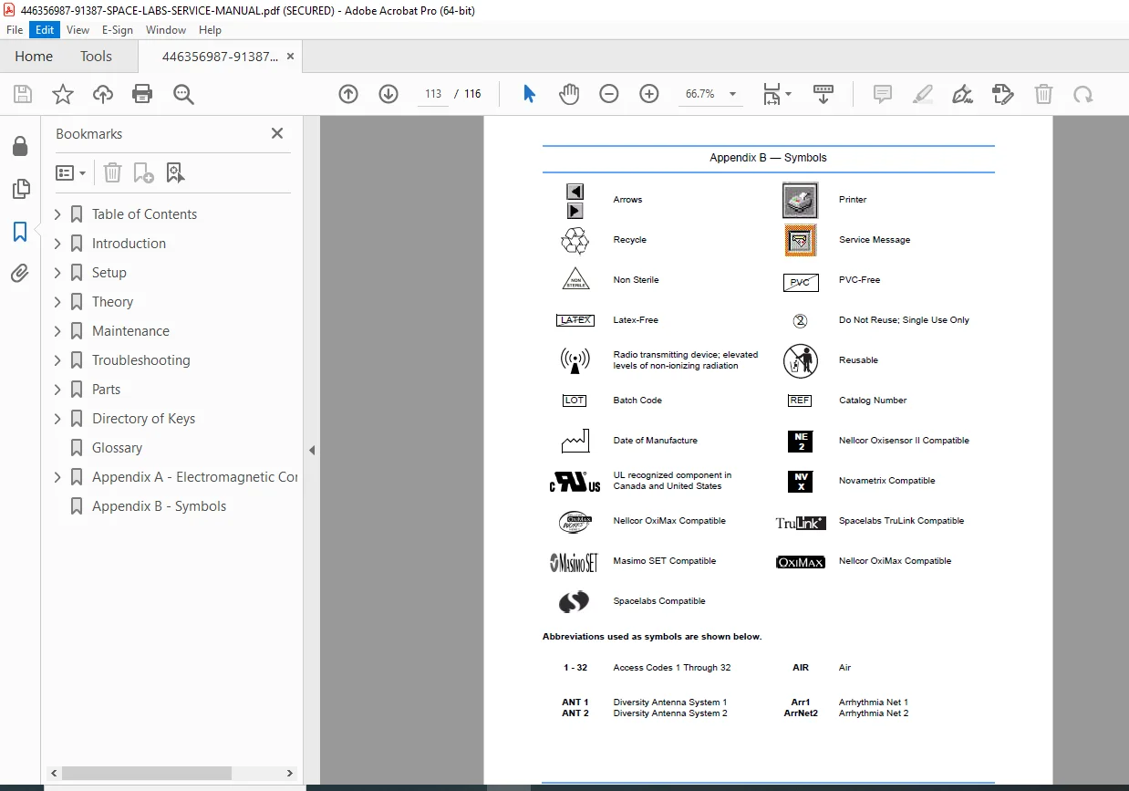
APPENDIX B: SYMBOLS
- Medical device symbols
- Safety symbols
- Warning symbols
- Regulatory symbols
- Connection symbols
Who Needs This Manual?
This Spacelabs Medical 91387 service manual is essential for:
- Certified biomedical equipment technicians (CBET)
- Hospital clinical engineering departments
- Spacelabs Medical authorized service centers
- Medical equipment service companies
- Critical care technical support personnel
- Anyone performing authorized service on 91387 monitors
Prerequisites:
✓ Spacelabs Medical service training
✓ Patient monitoring system experience
✓ IEC 60601-1 medical electrical safety knowledge
✓ Networking and IT fundamentals
✓ Electronic troubleshooting skills
✓ ESD handling procedures
✓ Understanding of physiological parameters
FILE DETAILS
| Detail | Specification |
|---|---|
| Manual Title | 91387 Service Manual |
| Models Covered | 91387-27, 91387-28 (bedside), 91387-38 (central) |
| Part Number | 070-1159-00 |
| Revision | F |
| Publication Date | March 14, 2007 |
| Manufacturer | Spacelabs Medical, Inc., Issaquah, WA, USA |
| Pages | 116 pages |
| PDF Quality | High-quality technical manual with diagrams |
| File Size | 2.8 MB |
| Page Size | Letter (612 x 792 pts) |
| Language | English |
| Creator | FrameMaker 7.0 |
| PDF Version | 1.6 |
| Security | Print allowed, copy allowed |