
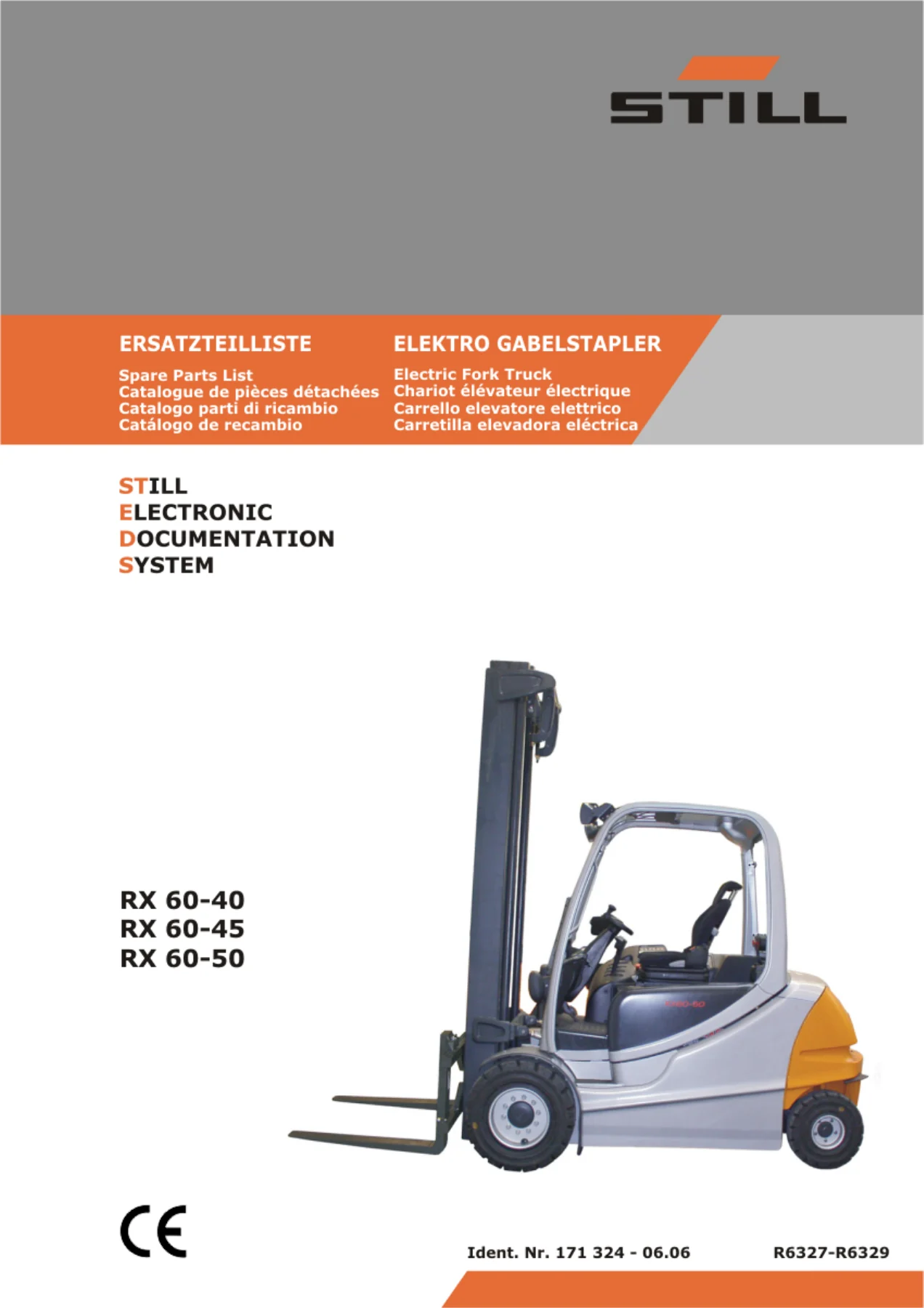
STILL RX 60-40 RX 60-45 RX 60-50 Electric Forklift Spare Parts Catalogue 516327A00006 – Illustrated Parts Manual PDF
Original price was: $65.95.$46.95Current price is: $46.95.
Complete 381-page illustrated spare parts catalogue for STILL RX 60-40, RX 60-45 and RX 60-50 electric forklift trucks. Every component indexed by figure number, STILL part number, quantity, description, norm and type, with exploded diagrams across all major assemblies. Document 516327A00006, dated 06.01.2010. Instant PDF download.
Description
STILL RX 60-40, RX 60-45 & RX 60-50 Electric Forklift Spare Parts Catalogue — Complete Illustrated Parts Reference
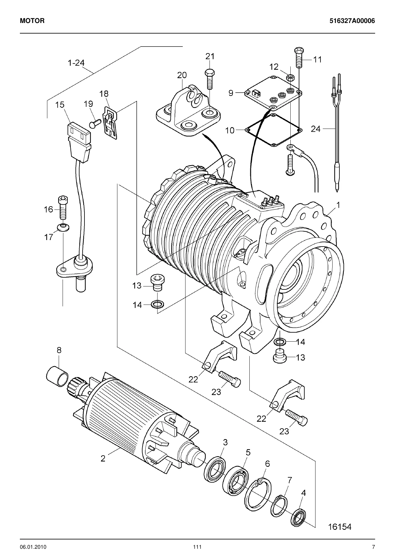
This is the complete illustrated spare parts catalogue for the STILL RX 60-40, RX 60-45 and RX 60-50 electric counterbalance forklift trucks. Published under document number 516327A00006 and dated 06.01.2010, it contains the full parts breakdown across every major assembly of these electric trucks — from the traction motor and mechanical drive axle through the mast, hydraulics, operator compartment, electronics and body panels. Every listed part is tied to an exploded illustration and a data table showing figure number, STILL part number, quantity, description, remarks, DIN/ISO norm and type designation.
The catalogue is presented in English and German. The title page carries the manual’s own titles in all five published languages: ERSATZTEILLISTE (German), Spare Parts List (English), Catalogue de pièces détachées (French), Catalogo parti di ricambio (Italian) and Catálogo de recambio (Spanish). Parts descriptions, remarks and norm references appear in English and German throughout, reflecting STILL’s international service documentation format.
File Details
- Manual type: Illustrated Spare Parts Catalogue (Ersatzteilliste)
- Brand / manufacturer: STILL
- Models covered: RX 60-40, RX 60-45, RX 60-50
- Document number: 516327A00006
- Date: 06.01.2010
- Languages: English, German (title page also printed in French, Italian and Spanish)
- Page count: 381 pages
- File format: PDF
Chapters Covered
- Electric Motor
- Mechanical Drive Axle
- Chassis
- Operator’s Compartment
- Steering System
- Wheels and Tyres
- Braking System
- Controls
- Display Element
- Electrics; Electronics
- Electronic Controls
- Hydraulics
- Working Hydraulics
- Valve
- Load Lifting System
- Mast
- Other Accessories
Electric Motor and Drive Axle Assemblies
The electric motor chapter covers the complete drive motor assembly, including AT and GT drive motor variants, stator, armature, shaft seals, radial seals, grooved ball bearings, lock rings, sleeve bearings, clamping pieces, sensors, cable trees and the temperature sensor repair kit with its specified adhesive. The mechanical drive axle chapter documents the wheel drive units for both left and right sides, covering gearings, wheel hubs, wheel bolts, taper roller bearings, planetary gears, ring gears, pinions, breathers, housings and O-rings. Brake components installed in the drive axle are broken out with brake discs, brake pistons, adjusters, brake cams, springs, levers and flange hardware.
Chassis, Counterweight and Body Panels
The chassis section lists the complete counterweight assembly, floor plates, floor mats, travel sender, mudguards, clutch pins and mounting hardware. The covering chapter documents front and rear panelling, hood covers, protective covers, headliners, roof coverings, badges, hinges, clamps and fasteners. Body panel fasteners are fully specified with norm references and tightening types.
Operator’s Compartment, Seat and Overhead Guard
The operator’s compartment chapter lists the complete driver’s seat (MSG 65 and MSG 75 variants with interchangeable mounting parts), including cushions, backrests, seat belts, buckles, rails, handles, armrests and adjusting devices. The overhead guard assembly is documented with spring elements, washers, bushes, lock edge washers, bearing flanges and caps. Mirror assemblies, support brackets and mounting hardware are also included.
Steering, Braking and Controls
Steering system coverage includes the steering column (with the week 07/2007 and week 08/2007 variants), steering wheel, clamping pieces, magnets, sensors, pressure switches, steer unit and associated seals and bearings. The braking system chapter documents the handbrake control, brake cables, parking brake assembly with toothed segment, potentiometer, shoe, perforated plate and all related springs, pins and fasteners. Driving controls — twin-pedal and two-pedal configurations — are also covered, along with control units and switches.
Electrics, Electronics and Display
The electrics and electronics chapter contains the full wiring harness documentation, including cable trees for roof, frame and counterweight installation, plug and socket housings, contacts, seals, caps and covers. Lighting coverage includes headlights, rear lights, bulbs, reflectors, searchlights, working lights and the complete hazard warning system with signal transmitter. Display elements include the Fleet Manager with card reader and keypad variants. Traction control, controllers (main control unit and 80-volt supply unit) and inverters are listed with their respective part numbers and variants.
Hydraulics and Working Hydraulics
The hydraulics chapter covers the standard hydraulic system including the hydraulic pump, valve assemblies, seal kits, pipe unions, O-rings, return flow filters (with and without breather filter, including the week 39/2008 change), hose lines, high-pressure hoses, clamps, threaded pipes and unions. Working hydraulics controls are documented for direction switch, tilt, 3rd lever and 4th lever configurations, with symbol plates and cross-section reducers. The control valve chapter details the 4-function standard directional control valve block with mounting flanges, rubber mountings, levers, axles, bolts and seal kits across the various production-week variants.
Load Lifting System and Mast
The load lifting system chapter covers the mast pivot bearing assembly with cheese-head screws, lock washers and plugs. The mast chapter documents the complete triplex upright assembly (mast height 2500 mm) including outer, central and inner lift masts, lift cylinders for centre and right/left positions, high-pressure hoses and leaf chains in three lengths (2458 mm, 1897 mm, 1795 mm). Lift cylinder construction parts, cylinder heads, piston rods, cylinder barrels, seal kits and adhesives are all listed.
Wheels, Tyres and Other Accessories
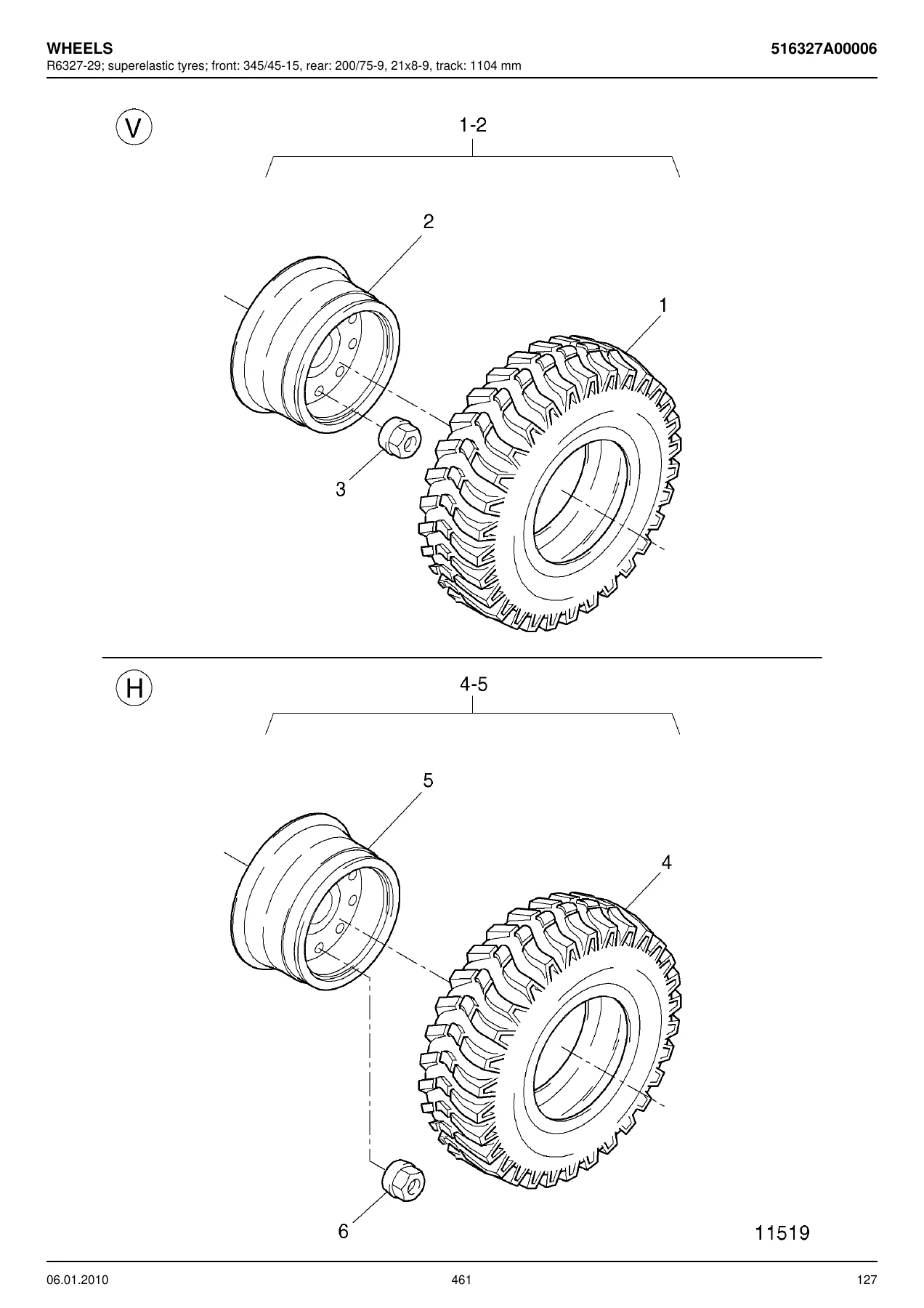
The wheels and tyres chapter lists superelastic tyre assemblies for front and rear, including Trelleborg and Solideal Magnum front tyres (345/45-15), rear tyres (200/75-9, 21×8-9), disc wheels, wheel nuts and track width data (1104 mm). Fender assemblies are also covered. Other accessories include labels, plates, warning signs, identification plates, test plaques, type plates and the RX60-40 identification plate set.
Why This Parts Catalogue Matters
Ordering the wrong part on an electric forklift is expensive in both money and downtime. This catalogue removes the guesswork: every component is indexed by figure number, STILL part number and quantity, with exploded diagrams that show exactly how parts fit together. Whether you are rebuilding a drive axle, replacing a brake piston, tracing a hydraulic leak, ordering a replacement contactor, sourcing a seat cushion, or identifying the correct seal kit for a specific production week, the illustration and table together give you the exact part number to quote — nothing more, nothing less.
The catalogue also captures the production-week changes that STILL incorporated across the RX 60-40/45/50 build run, including the week 39/2008 return flow filter change, the week 43/2006 control valve update, the week 07/2007 and 08/2007 steering column variants, and the week 45/2006 and 46/2006 seat washer change. For workshops maintaining a mixed fleet, this level of revision detail prevents ordering a part that will not fit the truck in front of you.
IMAGES PREVIEW
Instant PDF Delivery
This STILL RX 60-40, RX 60-45 and RX 60-50 spare parts catalogue is delivered as an instant PDF download — no shipping, no waiting. Read it on a laptop, tablet or phone, print the pages you need for the workshop floor, or keep it on your service vehicle for on-site reference. The complete 381-page document is yours the moment checkout is complete, giving your parts department, workshop or maintenance team immediate access to the full illustrated parts breakdown for these electric forklift trucks.
Reviews
There are no reviews yet.