
Suzuki AN400 K7 K8 K9 Burgman 400 Scooter Service Manual 2007-2009 Full Workshop Guide
Original price was: $29.95.$17.95Current price is: $17.95.
Complete Suzuki AN400 K7, K8 and K9 service manual covering the 400cc Burgman scooter from 2007 through 2009. Full engine, transmission, brake, suspension, fuel injection and electrical procedures with specifications, torque values and wiring diagrams.
Description
Suzuki AN400 K7 K8 K9 Service Manual – Full Workshop Coverage
This Suzuki AN400 K7 K8 K9 Service Manual is the complete workshop reference for the 400cc Burgman scooter produced across the 2007, 2008 and 2009 model years. It brings together every system on the machine — from the fuel-injected single-cylinder engine and CVT transmission through to the brake-lock parking system, cooling circuit and full wiring network — into one PDF you can open on any device.
Whether you are servicing a UK-market K7, a US-spec K8 or an Australian-delivered K9, the procedures in this AN400 workshop manual are organised by system so you can move straight to the job in front of you: top-end disassembly, crankcase splitting, V-belt replacement, brake bleeding, suspension rebuilds or FI diagnostics.
File Details
- Manual type: Service / Workshop Manual
- Brand: Suzuki
- Model: AN400 (Burgman 400)
- Model years covered: AN400K7, AN400K8, AN400K9
- Language: English
- Page count: 475 pages
- File format: PDF
- Publication date: April 2006
- Part number: 99500-34100-01E
Chapters Covered in This Suzuki AN400 K7 K8 K9 Workshop Manual
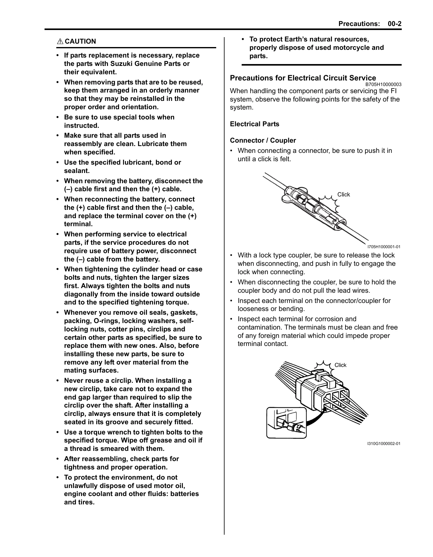
- Section 00 – Precautions: Warning/caution/note conventions, general precautions, electrical circuit service precautions, connector and coupler handling, fuse and battery procedures, multi-circuit tester use.
- Section 0 – General Information: Symbols, abbreviations, vehicle side views, VIN and engine serial locations, fuel/oil/coolant recommendations, break-in procedures, country and area codes, wire colour symbols, warning labels, electrical component locations, specifications, special tools.
- Section 0B – Maintenance and Lubrication: Periodic maintenance schedule, recommended fluids and lubricants, lubrication points, air cleaner element, spark plug, valve clearance inspection and adjustment, fuel line, engine oil and filter change, final reduction gear oil, cooling fan filter, drive V-belt, throttle cable play, cooling system inspection and air bleeding, radiator hoses, brake system, brake fluid, tires, steering, front fork, rear suspension, exhaust mounting, chassis bolt and nut torque checks, compression pressure, oil pressure, SDS check, automatic clutch inspection, parking brake.
- Section 0C – Service Data: Full standard and limit specification tables for the whole machine plus tightening torque specifications.
- Section 1A – Engine General Information and Diagnosis: Injection timing and compensation, self-diagnosis function (user mode / dealer mode), FI system wiring diagram, ECM coupler terminal alignment, FI parts location, engine symptom diagnosis, DTC table, fail-safe function, troubleshooting for C12 through C44 codes, SDS diagnostic procedures.
- Section 1B – Emission Control Devices: Fuel injection system description, crankcase emission control (PCV), exhaust emission control and three-way catalyst, noise emission control, HO2 sensor removal/inspection, PCV hose.
- Section 1C – Engine Electrical Devices: ECM, CKP sensor, IAP sensor, TP sensor, ECT sensor, speed sensor, IAT sensor, TO sensor, STP sensor and adjustment, ISC valve pre-set and inspection, HO2 sensor.
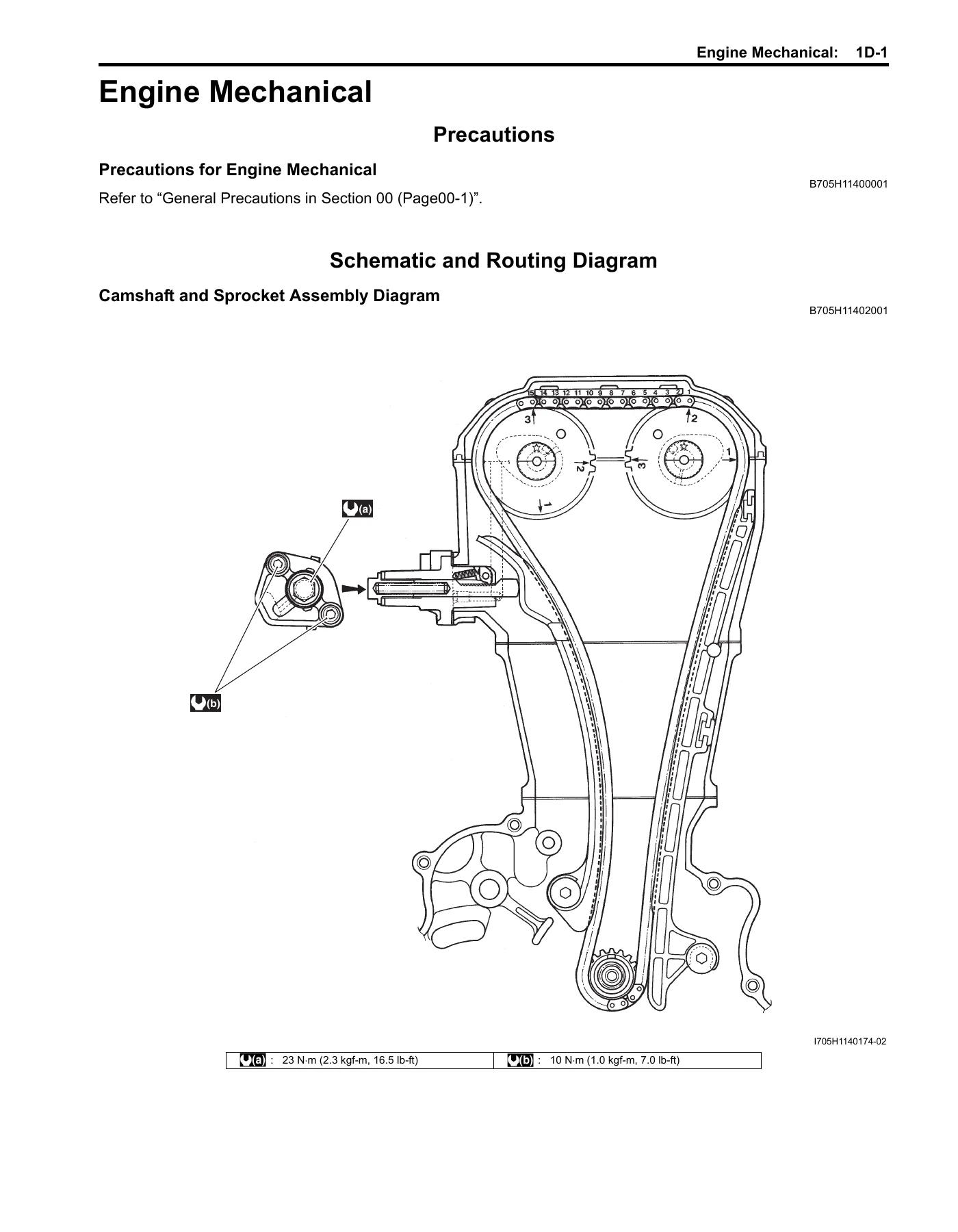
- Section 1D – Engine Mechanical: Compression pressure check, engine removal and installation, air cleaner box, throttle body construction, engine top side disassembly and assembly, camshaft inspection, cam chain tensioner, cylinder head disassembly and reassembly, valve guide and valve seat repair, cylinder and piston, engine bottom side disassembly and assembly, conrod and crankshaft inspection, bearings.
- Section 1E – Engine Lubrication System: Lubrication circuit diagrams, oil pressure check, oil sump filter, oil pump removal and inspection, piston cooling nozzle.
- Section 1F – Engine Cooling System: Cooling system description, engine coolant description, thermo-switch, ECT sensor, cooling circuit diagram, radiator hose routing, cooling circuit inspection, radiator cap, radiator removal and cleaning, radiator hoses, reservoir tank, cooling fan, thermostat, water pump components and rebuild.
- Section 1G – Fuel System: Fuel tank hose construction, fuel system diagnosis, fuel cut valve, fuel tank removal and installation, fuel pump assembly and disassembly, FTPC valve, fuel pressure inspection, fuel pump relay, fuel mesh filter, fuel level gauge, fuel discharge inspection, fuel injector.
- Section 1H – Ignition System: Immobilizer description, ignition system diagram and symptom diagnosis, ignition coil inspection and peak voltage, CKP sensor peak voltage and resistance, engine stop switch, ignition switch.
- Section 1I – Starting System: Starting system diagram, starter motor will not run troubleshooting, starter motor components and rebuild, brush and commutator inspection, starter relay, turn signal / side-stand relay, side-stand interlock system, starter clutch.
- Section 1J – Charging System: Charging circuit diagram, symptom diagnosis, battery current leakage, regulated voltage, generator coil resistance, generator no-load performance, regulator/rectifier, generator removal and installation, battery components, initial charging, recharging.
- Section 1K – Exhaust System: Exhaust system components, exhaust pipe and muffler removal and installation, exhaust system inspection, HO2 sensor inspection.
- Section 2A – Suspension General Diagnosis: Suspension and wheel symptom diagnosis tables.
- Section 2B – Front Suspension: Front fork components, removal and installation, disassembly and assembly, oil level adjustment, spring free length, cylinder and cylinder ring inspection.
- Section 2C – Rear Suspension: Rear suspension components and assembly, rear swingarm, rear shock absorber removal and gas pressure release, rear suspension adjustment, cushion lever and rod inspection, crankcase bracket.
- Section 2D – Wheels and Tires: Front and rear wheel components, removal and installation, wheel related parts inspection, tire removal and installation, wheel/tire/air valve inspection, air valve, wheel balance, specifications.
- Section 3A – Drive Chain / Drive Train / Drive Shaft: Final gear components, final gear assembly removal and installation, final gear disassembly and assembly, final drive gear bearing inspection.
- Section 4A – Brake Control System and Diagnosis: Front and rear brake hose routing, brake symptom diagnosis, brake light switch, brake fluid level, brake hose inspection, air bleeding, brake fluid replacement, front and rear master cylinder assemblies and rebuild, master cylinder parts inspection.
- Section 4B – Front Brakes: Front brake components, pad inspection and replacement, caliper removal and rebuild, caliper parts inspection, disc removal and inspection.
- Section 4C – Rear Brakes: Rear brake components, pad inspection and replacement, caliper removal and rebuild, brake caliper piston disassembly and assembly, caliper parts inspection, disc removal and inspection.
- Section 4D – Parking Brake: Brake-lock system description, automatic parking brake adjuster, over-adjust prevention, brake-lock cable routing, inspection, removal and installation, adjustment.
- Section 5A – Automatic Transmission: Drive train system diagram, symptom diagnosis, clutch in / stall speed inspection, V-belt type CVT removal and installation, drive V-belt inspection, cooling fan filter, inner clutch cover bearings, movable drive face, oil seals, clutch shoe and movable driven face disassembly and parts inspection.
- Section 6A – Steering General Diagnosis: Steering symptom diagnosis.
- Section 6B – Steering / Handlebar: Handlebar components, removal and installation, handlebar inspection, steering components, steering removal and installation, related parts inspection, steering stem bearing removal and installation, steering tension adjustment.
- Section 9A – Wiring Systems: Full wiring diagram (E-02, 19, 24, 54 and E-03, 28, 33 variants), wiring harness routing, service data.
- Section 9B – Lighting Systems: Front combination light components and removal, headlight/turn signal/position light bulb replacement, headlight beam adjustment, rear reflector/rear combination light/license light, turn signal / side-stand relay, dimmer switch, turn signal switch, passing light switch, horn button, brake light switches, hazard switch, engine stop switch, starter button, ignition switch, parking brake switch, trunk box switch.
- Section 9C – Combination Meter / Fuel Meter / Horn: Combination meter components and removal, disassembly and assembly, combination meter inspection, fuel level meter and gauge inspection, speedometer and speed sensor, ignition switch, horn.
- Section 9D – Exterior Parts: Seat lock cable routing, exterior components location, removal procedures flow chart, exterior parts components, inner cover construction, seat lock cable, handlebar covers, meter panels, leg shields, under cover, helmet box, seat, front box, pillion rider handle, frame covers, footboards.
- Section 9E – Body Structure: Body frame construction, engine mounting bracket and bushing replacement, side-stand construction, side-stand removal and installation, center stand construction and removal.
What ties all of this together is that the AN400 Burgman is a scooter with a very particular architecture — a wet-sump single fed by fuel injection, an automatic centrifugal clutch, a variable-ratio V-belt drive train, a final reduction gear set and a disc brake front and rear with a mechanical parking brake-lock. That means several of the procedures in this book cannot be improvised from a generic scooter manual: the CVT belt inspection and movable drive face rebuild, the automatic clutch engagement and lock-up test, the brake-lock adjuster mechanism, the ISC valve pre-set routine and the cooling system air-bleeding sequence all follow model-specific steps. This Suzuki Burgman 400 service manual walks through each one with the measurements, tightening torques and service limits that the factory procedure requires, plus the FI diagnostic flow charts and full wiring diagrams needed when the engine management side misbehaves.
What This Suzuki AN400 K7 K8 K9 Repair Manual Lets You Do
With this manual in hand you can carry out a full periodic service on the AN400 to the intervals and settings Suzuki specifies, including valve clearance measurement and shim replacement, engine oil and filter change, final reduction gear oil replacement, drive V-belt width check and replacement, throttle cable play adjustment and cooling circuit bleeding. You can pull the top end apart for a valve job or piston replacement, split the crankcase to service the crankshaft and oil pump, and rebuild the CVT — movable drive face, rollers, dampers, clutch shoe and movable driven face — with the correct clearances and grease points.
On the chassis side the AN400 service manual covers the telescopic front fork rebuild with oil level setting, the rear shock absorber and linkage assembly, the rear swingarm bearings and dust seals, wheel bearing replacement and tyre fitting. The braking chapters guide you through pad replacement, caliper rebuilds with the piston seal and dust seal orientation, brake fluid replacement and air bleeding, and the parking brake-lock cable adjustment that many owners neglect.
Electrical coverage is equally practical: this Suzuki AN400 workshop manual includes the full wiring diagram for both the earlier and later market variants, plus continuity test procedures for the dimmer, turn signal, passing light, horn, hazard, engine stop, starter button, ignition switch, brake-lock switch and trunk box switch. The FI section goes further, giving you the DTC table, the fail-safe behaviour for each sensor, and step-by-step troubleshooting for codes C12 through C44 — CKP sensor, IAP sensor, TP sensor, ECT sensor, speed sensor, IAT sensor, TO sensor, ignition, STVA, STPS, fuel injector, ISC valve, FP relay, IG switch and the HO2 sensor. That is the difference between guessing at an FI light and following the actual diagnostic path with the right meter settings.
Getting the specifications right matters because so much of this machine depends on them. An ISC valve that has not been pre-set correctly will not idle properly. A CVT belt below the service limit will slip under load. A steering stem nut torqued without the break-in and re-check sequence will either bind or feel loose. Brake caliper pistons installed without the correct seal orientation leak or drag. The torque tables scattered through every chapter of this manual — and consolidated in the tightening torque specifications — exist precisely so that these jobs are done once and done correctly.
IMAGES PREVIEW
Delivery is instant. Once your order is placed, the Suzuki AN400 K7 K8 K9 service manual is available as a PDF download — no shipping, no waiting, no physical book to store. Open it on a laptop or tablet in the garage, print the pages for the job you are doing, and keep the rest of the manual clean. Because it is a PDF, you can zoom into the exploded views and wiring diagrams, and print individual pages or whole sections as often as you like.
Who This Suzuki Burgman 400 Service Manual Is For
This AN400 service manual suits the home mechanic maintaining a K7, K8 or K9 Burgman, the independent workshop taking on a scooter they do not see every day, and the owner who wants to understand what a dealer is proposing before authorising the work. It assumes the reader has proper tools and some mechanical background — the procedures reference Suzuki special tools by part number where they are needed — but it does not assume factory training. Every chapter is written for the person actually holding the wrench.

Reviews
There are no reviews yet.