
Suzuki DF140A DF115A DF115 DF115AZ DF140AZ DF115AS Engine Control Service Manual – PDF
Original price was: $29.95.$18.95Current price is: $18.95.
Suzuki Marine Engine Control service manual for DF140A, DF115A, DF115, DF115AZ, DF140AZ and DF115AS outboards – ECM, sensors, actuators, self-diagnostic codes, fail-safe values and full wiring terminal data in one downloadable PDF.
Description
Suzuki DF140A / DF115A Engine Control Service Manual
This Suzuki Marine service manual covers the Engine Control section for the DF140A, DF115A, DF115, DF115AZ, DF140AZ and DF115AS four-stroke outboards. It is the diagnostic and electrical control volume of the Suzuki service literature, written for the technician who has to trace a fault through the ECM, the sensor network and the actuator circuits rather than rebuild a powerhead. Every procedure is built around the Suzuki Diagnostic System, the monitor-tachometer lamp and buzzer signals, and the self-diagnostic codes stored in the ECM memory.
File Details
- Manual type: Service Manual – Engine Control section
- Brand: Suzuki Marine
- Models covered: DF140A, DF115A, DF115, DF115AZ, DF140AZ, DF115AS
- Language: English
- Page count: 102 pages
- File format: PDF
- Section: Engine Control [8]
Chapters Covered
- Precautions
- General Description – Engine Control System Description, System Structure, Engine Control System Flow Diagram
- Engine Control Module (ECM) – controls, ECM Input/Output Circuit Diagram, 18-pin and 34-pin connector terminal tables
- Caution System Description – Over-Revolution, Low Oil Pressure, Overheat, Low Battery Voltage
- Self-Diagnostic System Description
- Fail-Safe System Description and pre-programmed values
- Operating Hour Indication System Description
- Oil Change Reminder System Description and cancellation procedure
- Water in Fuel Alert System Description
- Troll Mode System Description, setting, adjusting and cancelling
- Component Location
- Diagnostic Information and Procedures
- Self-Diagnostic Code 3-4 MAP Sensor
- Self-Diagnostic Code 1-4 Cylinder Temp. Sensor
- Self-Diagnostic Code 2-3 IAT Sensor
- Self-Diagnostic Code 4-2 CKP Sensor
- Self-Diagnostic Code 2-4 CMP Sensor
- Self-Diagnostic Code 2-2 Air Intake System
- Self-Diagnostic Code 3-2 MAP Sensor 2
- Self-Diagnostic Code 1-5 Ex. Manifold Temp. Sensor
- Self-Diagnostic Code 4-3 Fuel Injector
- Self-Diagnostic Code 2-1 TPS (Throttle Position Sensor)
- Self-Diagnostic Code 1-1 Rectifier / Regulator (Over Charging)
- Self-Diagnostic Code 5-3 Oil Pressure Switch
- Self-Diagnostic Code 3-7 Trim Sensor
- Self-Diagnostic Code 5-4 Knock Sensor (DF115A/140A)
- Self-Diagnostic Code 3-6 O2 Sensor
- Self-Diagnostic Code 6-3 O2 Sensor Heater
- Troubleshooting Without Self-Diagnostic Code
- IAC System Troubleshooting
- Service Instructions
- Inspection of the ECM and Its Circuit
- ECM Main Relay Inspection
- ECM Removal and Installation
What makes this particular Suzuki Engine Control manual worth having is that it does not stop at describing a symptom. Each self-diagnostic code chapter gives the condition that triggers the code, then walks through numbered troubleshooting steps with a Yes/No branch at every measurement point. You are told which wire colour to probe, which terminal number on the ECM connector to reference, what voltage range to expect and what each result means. The 34-pin and 18-pin ECM connector terminal tables list every pin by wire colour and circuit, so tracing a suspect circuit from sensor to module is a matter of reading the table rather than guessing.
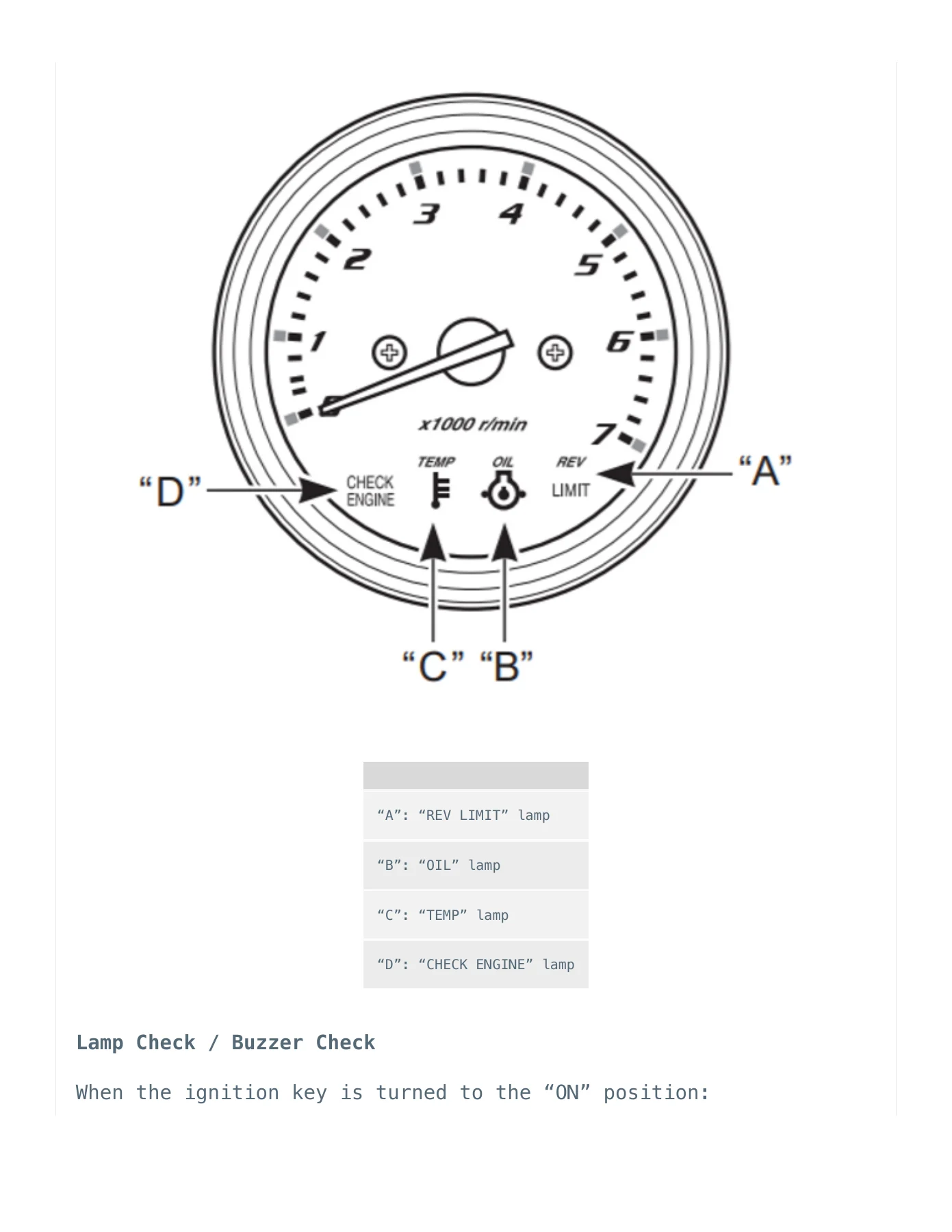
The manual also documents the four caution systems and how the operator sees them on the monitor-tachometer. Over-revolution, low oil pressure, overheat and low battery voltage each have their own trigger conditions, lamp behaviour and buzzer pattern, and the reset procedure for each is spelled out. The gradient overheat logic is covered in detail, including the temperature-difference limits measured over three consecutive ten-second periods on both the cylinder temperature sensor and the exhaust manifold temperature sensor. Knowing those numbers is the difference between condemning a good engine and catching a genuine cooling problem early.
Fail-safe values are another section that earns its place on the bench. If a sensor drops out, the ECM substitutes a pre-programmed value so the engine keeps running, and this manual lists those values item by item – MAP sensor, cylinder temp, IAT, exhaust manifold temp, throttle position, trim and knock. That tells you exactly how the engine will behave while a fault is present, which is often the fastest way to confirm which sensor has actually failed.
Operator-facing systems are covered as well. The operating hour indication chart explains how the tachometer needle position and REV-LIMIT lamp flashes combine to display total engine hours in 500-hour blocks up to and beyond 2,040 hours. The oil change reminder system has its activation logic and the full emergency stop switch cancellation procedure – pull the knob three times within ten seconds and listen for the confirming beep. The water in fuel alert and the troll mode system, including the 50 r/min per press adjustment and the upper and lower limit beeps, are documented with the same care.
Jobs and Repairs This Manual Supports
- Reading and clearing self-diagnostic codes on DF140A, DF115A, DF115, DF115AZ, DF140AZ and DF115AS outboards
- Testing MAP sensor, TPS, IAT sensor, cylinder temperature sensor and exhaust manifold temperature sensor circuits
- Diagnosing CKP and CMP sensor faults, including air gap and resistance checks
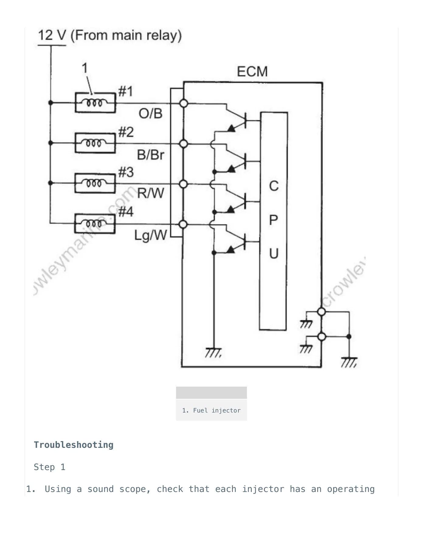
- Fuel injector operation testing and injector resistance verification
- IAC valve resistance and duty cycle testing for idle and trolling faults
- O2 sensor and O2 sensor heater circuit diagnosis
- Knock sensor inspection on DF115A and DF140A
- Trim sensor, oil pressure switch and rectifier/regulator over-charging diagnosis
- ECM power and ground circuit verification using the test cord set
- ECM main relay continuity and coil resistance inspection
- ECM removal and installation
- Troubleshooting unstable idle and trolling with no stored code
Why This Manual Matters
Modern Suzuki outboard faults rarely announce themselves. A misfire, a rev limit that engages early, an intermittent warning lamp or an engine that drops to 3,000 r/min on its own can come from any of a dozen circuits. Working without the correct terminal numbers, wire colours, expected voltages and resistance ranges turns a straightforward diagnosis into parts swapping. This manual supplies those numbers directly from the manufacturer’s test procedure, along with the priority order in which multiple simultaneous codes are displayed, the 20-30 second window the ECM needs to clear an indication after a repair, and the special handling required for the oil pressure switch code. It also carries the safety precautions that matter when you are cranking an engine with fuel injectors still connected or working around a pressurised fuel system.
IMAGES PREVIEW
Instant PDF Delivery
Your Suzuki DF140A DF115A DF115 DF115AZ DF140AZ DF115AS Engine Control service manual is delivered as a downloadable PDF the moment payment clears. There is no shipping, no waiting and no physical book to lose in the workshop. Open it on a laptop, tablet or phone at the boat, print only the pages for the job in front of you, and keep the rest clean for the next fault. Whether you are a dealer technician chasing a stored code or an owner who wants to understand what the CHECK ENGINE lamp is telling you, having the full Engine Control procedure set on hand turns guesswork into a measured, repeatable diagnosis.
Reviews
There are no reviews yet.