Trusted Business
Verified & Licensed
Virus Free Files
100% Safe Downloads
Secure Payment
SSL Protected
Instant Delivery
Available Immediately
Suzuki SX4 RW419D with D19AA Engine Supplementary Service Manual – PDF DOWNLOAD
$30.95
Suzuki SX4 RW419D with D19AA Engine Supplementary Service Manual – PDF DOWNLOAD
Instant PDF Download
Available immediately
Save to Your Device
Download & keep forever
Antivirus Scanned
100% virus-free
Trusted Worldwide
175,000+ customers
Description
Suzuki SX4 RW419D with D19AA Engine Supplementary Service Manual – PDF DOWNLOAD
FILE DETAILS:
Suzuki SX4 RW419D with D19AA Engine Supplementary Service Manual – PDF DOWNLOAD
Language : English
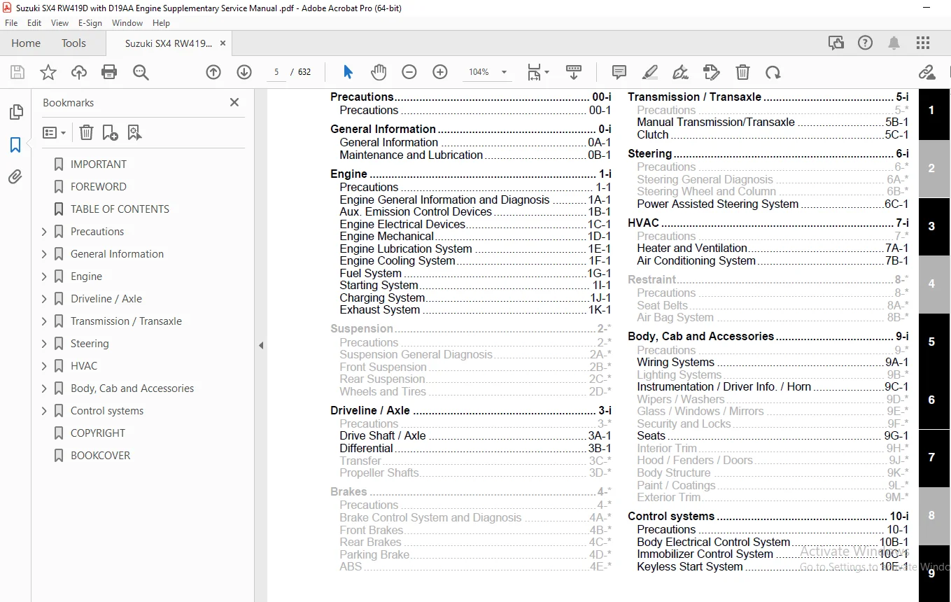
Pages : 632
Downloadable : Yes
File Type : PDF
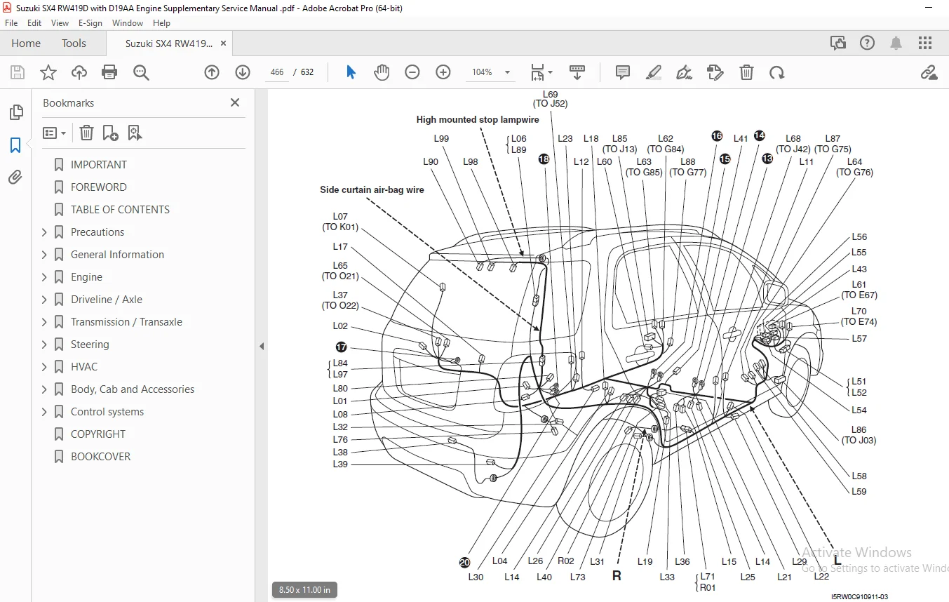
IMAGES PREVIEW OF THE MANUAL:
TABLE OF CONTENTS:
Suzuki SX4 RW419D with D19AA Engine Supplementary Service Manual – PDF DOWNLOAD
IMPORTANT...............................................................................................................................  1
FOREWORD................................................................................................................................  3
TABLE OF CONTENTS.......................................................................................................................  5
Precautions.............................................................................................................................  7
	Precautions.........................................................................................................................  8
		Precautions.....................................................................................................................  8
			General Precautions.........................................................................................................  8
			Precautions for Catalytic Converter and Diesel Particulate Filter........................................................... 10
General Information..................................................................................................................... 11
	General Information................................................................................................................. 12
		General Description............................................................................................................. 12
			Engine Identification Number................................................................................................ 12
		Component Location.............................................................................................................. 13
			Warning, Caution and Information Labels Location............................................................................ 13
	Maintenance and Lubrication......................................................................................................... 15
		Scheduled Maintenance........................................................................................................... 15
			Maintenance Schedule under Normal Driving Conditions........................................................................ 15
			Maintenance Recommended under Severe Driving Conditions..................................................................... 16
		Repair Instructions............................................................................................................. 17
			Accessory Drive Belt Inspection............................................................................................. 17
			Accessory Drive Belt Replacement............................................................................................ 17
			Camshaft Timing Belt Replacement............................................................................................ 17
			Valve Lash (Clearance) Inspection........................................................................................... 17
			Engine Oil and Filter Change................................................................................................ 17
			Engine Coolant Change....................................................................................................... 19
			Air Cleaner Filter Inspection............................................................................................... 19
			Air Cleaner Filter Replacement.............................................................................................. 19
			Fuel Filter Replacement..................................................................................................... 19
		Specifications.................................................................................................................. 19
			Tightening Torque Specifications............................................................................................ 19
		Special Tools and Equipment..................................................................................................... 20
			Recommended Fluids and Lubricants........................................................................................... 20
			Special Tool................................................................................................................ 20
Engine.................................................................................................................................. 21
	Precautions......................................................................................................................... 26
		Precautions..................................................................................................................... 26
			Precautions for Engine...................................................................................................... 26
	Engine General Information and Diagnosis............................................................................................ 27
		Precautions..................................................................................................................... 27
			Precautions on Engine Service............................................................................................... 27
			Precautions in Diagnosing Trouble........................................................................................... 27
			Statement on Cleanliness and Care........................................................................................... 27
		General Description............................................................................................................. 28
			Engine Diagnosis General Description........................................................................................ 28
			OBD System Description...................................................................................................... 28
			CAN Communication System Description........................................................................................ 29
			Electronic Control System Description....................................................................................... 31
			Diesel Particulate Filter Description....................................................................................... 36
			Diesel Particulate Filter Regeneration Description.......................................................................... 36
			Oil Life Monitoring System.................................................................................................. 37
		Component Location.............................................................................................................. 38
			Electronic Control System Components Location............................................................................... 38
		Diagnostic Information and Procedures........................................................................................... 39
			MIL Check................................................................................................................... 39
			Engine and Emission Control System Check.................................................................................... 40
			DTC Check................................................................................................................... 42
			DTC Clearance............................................................................................................... 42
			DTC Table................................................................................................................... 43
			Fail-safe Table............................................................................................................. 47
			Scan Tool Data.............................................................................................................. 50
			Visual Inspection........................................................................................................... 54
			Engine Basic Inspection..................................................................................................... 54
			Engine Symptom Diagnosis.................................................................................................... 55
			DTC P0016: Crankshaft Position - Camshaft Position Correlation.............................................................. 76
			DTC P0045: Turbo Boost Control Solenoid Circuit / Open...................................................................... 77
			DTC P0087 / P0088: Fuel Rail Pressure - Too Low / Too High.................................................................. 78
			DTC P0090: Fuel Pressure Regulator Control Circuit.......................................................................... 79
			DTC P0091: Fuel Pressure Regulator Control Circuit Low...................................................................... 80
			DTC P0092: Fuel Pressure Regulator Control Circuit High..................................................................... 80
			DTC P0093: Fuel System Leak Detected - Large Leak........................................................................... 81
			DTC P0094: Fuel System Leak Detected - Small Leak........................................................................... 82
			DTC P0095: Intake Air Temperature Sensor 2 Circuit.......................................................................... 82
			DTC P0100 / P0101: Mass Air Flow Circuit / Mass Air Flow Circuit Range / Performance........................................ 83
			DTC P010F: Mass Air Flow Sensitivity Drift.................................................................................. 83
			DTC P0110 / P0111: Intake Air Temperature Sensor 1 Circuit / Intake Air Temperature Sensor 1 Circuit Range / Performance.... 84
			DTC P0115: Engine Coolant Temperature Circuit............................................................................... 85
			DTC P0116: Engine Coolant Temperature Circuit Range / Performance........................................................... 85
			DTC P0120: Throttle Position Sensor Circuit................................................................................. 86
			DTC P0122: Throttle Position Sensor Circuit Low............................................................................. 86
			DTC P0168: Fuel Temperature Too High........................................................................................ 87
			DTC P0180: Fuel Temperature Sensor Circuit.................................................................................. 88
			DTC P0190: Fuel Rail Pressure Sensor Circuit................................................................................ 88
			DTC P0201 / P0202 / P0203 / P0204: Injector Circuit/Open - Cylinder 1 / Cylinder 2 / Cylinder 3 / Cylinder 4................ 88
			DTC P0216: Injector / Injection Timing Control Circuit...................................................................... 89
			DTC P0219: Engine Overspeed Condition....................................................................................... 89
			DTC P0220: Pedal Position Sensor Circuit.................................................................................... 89
			DTC P0230: Fuel Pump Primary Circuit........................................................................................ 90
			DTC P0235: Turbo Boost Sensor Circuit....................................................................................... 90
			DTC P0237 / P0238: Turbo Boost Sensor Circuit Low / High.................................................................... 91
			DTC P0262 / P0265 / P0268 / P0271: Cylinder 1 / 2 / 3 / 4 Injector Circuit High............................................. 93
			DTC P0335: Crankshaft Position Sensor Circuit............................................................................... 93
			DTC P0340: Camshaft Position Sensor Circuit................................................................................. 93
			DTC P0380: Glow Plug Circuit................................................................................................ 94
			DTC P0401: Exhaust Gas Recirculation Flow Insufficient Detected............................................................. 94
			DTC P0402: Exhaust Gas Recirculation Flow Excessive Detected................................................................ 95
			DTC P0403: Exhaust Gas Recirculation Control Circuit........................................................................ 96
			DTC P0480: Fan 1 Control Circuit............................................................................................ 96
			DTC P0481: Fan 2 Control Circuit............................................................................................ 97
			DTC P0482: Fan 3 Control Circuit............................................................................................ 98
			DTC P0500: Vehicle Speed Sensor............................................................................................. 99
			DTC P0503: Vehicle Speed Sensor Intermittent / Erratic / High...............................................................100
			DTC P0504: Brake Switch 1 / 2 Correlation...................................................................................100
			DTC P0520: Engine Oil Pressure Switch Circuit...............................................................................101
			DTC P0530: A/C Refrigerant Pressure Sensor Circuit..........................................................................102
			DTC P0560: System Voltage...................................................................................................102
			DTC P0601: Internal Control Module Memory Check Sum Error...................................................................102
			DTC P0606: ECM Processor....................................................................................................103
			DTC P060A: Shut Off Monitoring During Initialization........................................................................103
			DTC P060B: ADC Monitoring...................................................................................................103
			DTC P0611: ECM Performance..................................................................................................104
			DTC P061B: FMTC Map Non Strictly Monotonus..................................................................................104
			DTC P061C: Engine Speed Calculation in Overrun..............................................................................104
			DTC P062D: Injectors Specific Chip 1........................................................................................104
			DTC P062E: Injectors Specific Chip 2........................................................................................105
			DTC P0638: Throttle Actuator Control Range / Performance....................................................................105
			DTC P0641: Sensor Reference Voltage 1 Circuit / Open........................................................................106
			DTC P0645: A/C Clutch Relay Control Circuit.................................................................................106
			DTC P0651: Sensor Reference Voltage 2 Circuit / Open........................................................................107
			DTC P0683: Glow Plug Control Module to ECM Communication Circuit............................................................107
			DTC P0685: ECM Power Relay Control Circuit / Open...........................................................................108
			DTC P0697: Sensor Reference Voltage 3 Circuit / Open........................................................................108
			DTC P0704: Clutch Switch Input Circuit Malfunction..........................................................................108
			DTC P0748: Fuel Flow Actuator Circuit.......................................................................................109
			DTC P0778: Fuel Pressure Regulator Circuit..................................................................................110
			DTC P1205: Diesel Particulate Filter Flow Resistance Monitoring Too Low.....................................................110
			DTC P1206: Diesel Particulate Filter Flow Resistance Monitoring Too High....................................................111
			DTC P1218: Hard Ware Recovery...............................................................................................111
			DTC P1219: Diesel Particulate Filter Regeneration Not Ended.................................................................112
			DTC P1301: Fuel Injector Calibration Code Classification....................................................................112
			DTC P1605: Communication between CY310 and mP...............................................................................112
			DTC P1606: Hard Ware Module Communication...................................................................................113
			DTC P1618: Supply Voltage of CJ940 above Limit..............................................................................113
			DTC P1619: Supply Voltage of CJ940 below Limit..............................................................................113
			DTC P1623: SPI Communication................................................................................................114
			DTC P1667: Fuel Filter Heating..............................................................................................114
			DTC P2080 / P2081: Exhaust Gas Temperature Sensor Circuit Range / Performance / Intermittent................................114
			DTC P2084 / P2085: Exhaust Gas Temperature Sensor-2 Circuit Range / Performance / Intermittent..............................115
			DTC P2100 / P2101: Throttle Actuator Control Motor Circuit / Open / Range / Performance.....................................115
			DTC P2107 / P2108: Throttle Actuator Control Module Processor / Performance.................................................116
			DTC P2111 / P2112: Throttle Actuator Control System - Stuck Open / Stuck Closed.............................................116
			DTC P2135: Throttle / Pedal Position Sensor Voltage Correlation.............................................................116
			DTC P2146 / P2148: Fuel Injector Group 1 Supply Voltage Circuit / Open / High...............................................117
			DTC P2149 / P2151: Fuel Injector Group 2 Supply Voltage Circuit / Open / High...............................................117
			DTC P2226: Barometric Pressure Circuit......................................................................................117
			DTC P2264: Water in Fuel Sensor Circuit.....................................................................................117
			DTC P2293: Fuel Pressure Regulator Performance..............................................................................118
			DTC P2294: Fuel Pressure Regulator Control Circuit..........................................................................119
			DTC P2295: Fuel Pressure Regulator Control Circuit Low......................................................................119
			DTC P2296: Fuel Pressure Regulator Control Circuit High.....................................................................120
			DTC P2299: Brake Pedal Position / Accelerator Pedal Position Incompatible...................................................121
			DTC P2452: Differential Pressure Sensor Electrical Failure..................................................................121
			DTC P2453 / P2455: Differential Pressure Sensor Hose Line Monitoring / Plausibility.........................................122
			DTC P2505: ECM Power Input Signal...........................................................................................122
			DTC P2620: Throttle Position Output Circuit / Open..........................................................................122
			DTC U1601: Control Module Communication Bus Off.............................................................................123
			DTC U1700: Lost Communication with Body Control Module......................................................................124
			DTC U1706: Lost Communication with ABS or ESP‚ Control Module...............................................................125
			DTC U1711: Lost Communication with 4WD Control Module.......................................................................126
			Table - 1040AA: Check on Supply Voltage and Current Uptake..................................................................128
			Table - 1040OA: Fuel Supply System Check....................................................................................128
			Table - 1048OA: Air Intake / Vacuum Circuit Check...........................................................................130
			Table - 1060EA: Fuel Temperature Sensor Check...............................................................................131
			Table - 1060FA: Injector Operation Check....................................................................................132
			Table - 1060FB: Injector Circuit Operation Check............................................................................134
			Table - 1060GD: Barometric Pressure Check...................................................................................137
			Table - 1060GF: Boost Pressure Check........................................................................................137
			Table - 1060GG: Check Measured Air Mass.....................................................................................138
			Table - 1060GH: Diesel Fuel Pressure Check..................................................................................139
			Table - 1060GI: Engine Speed Check..........................................................................................140
			Table - 1060GL: Main Relay Operation Check..................................................................................141
			Table - 1060GM: Sensor Power Supply 1 Circuit Check.........................................................................142
			Table - 1060GN: Sensor Power Supply 2 Circuit Check.........................................................................143
			Table - 1060GO: Inlet Throttle Valve Operation Check........................................................................145
			Table - 1060GP: Sensor Power Supply 3 Circuit Check.........................................................................146
			Table - 1060GQ: Fuel Filter Water Detection Sensor Operation Check..........................................................147
			Table - 1060GR: Fuel Pressure Regulator Operation Check.....................................................................148
			Table - 1060GS: MAF Sensor Operation Check..................................................................................148
			Table - 1060OE: ECT Sensor Operation Check..................................................................................149
			Table - 1064BB: Boost Pressure Control Solenoid Valve Operation Check.......................................................150
			Table - 1064BD: IAT Sensor 2 Check..........................................................................................150
			Table - 1068AC: Accelerator Pedal Check.....................................................................................151
			Table - 1080BE: Particulate Filter Saturation Check.........................................................................153
			Table - 1080BF: Differential Pressure Sensor Operation Check................................................................154
			Table - 1080BG: Exhaust Gas Temperature Sensor-1 Operation Check............................................................155
			Table - 1080BH: Exhaust Gas Temperature Sensor-2 Operation Check............................................................155
			Table - 1080CB: EGR Valve Operation Check...................................................................................156
			Table - 3340AB: Speed Signal Check..........................................................................................157
			Table - 5505AC: Fuel Heater Operation Check.................................................................................157
			Table - 5510CG: CMP Sensor Operation Check..................................................................................158
			Table - 5520CA: Glow Plugs Operation Check..................................................................................159
			Table - 5530BB: Battery Voltage Check.......................................................................................160
			Low Fuel Pressure Circuit Check.............................................................................................161
			High Fuel Pressure Circuit Check............................................................................................163
		Special Tools and Equipment.....................................................................................................164
			Special Tool................................................................................................................164
	Aux. Emission Control Devices.......................................................................................................165
		Repair Instructions.............................................................................................................165
			EGR Valve Inspection........................................................................................................165
			Exhaust Gas Temperature Sensor 1 and 2 Removal and Installation.............................................................165
			Exhaust Gas Temperature Sensor 1 and 2 Inspection...........................................................................165
			Differential Pressure Sensor Removal and Installation.......................................................................165
	Engine Electrical Devices...........................................................................................................166
		Precautions.....................................................................................................................166
			Precaution in Replacing ECM.................................................................................................166
		General Description.............................................................................................................166
			ECM Registration............................................................................................................166
		Repair Instructions.............................................................................................................167
			Idle Speed Inspection.......................................................................................................167
			Engine Control Module (ECM) Removal and Installation........................................................................167
			Registration for ECM Replacement............................................................................................167
			Fuel Injector Registration..................................................................................................168
			Fuel Pressure Sensor Data Initialization....................................................................................168
			Diesel Particulate Filter Data Initialization...............................................................................168
			Differential Pressure Sensor Data Initialization............................................................................168
			Pre-catalytic Converter Data Initialization.................................................................................168
			Diesel Particulate Filter After-sales Regeneration..........................................................................168
			After-sales Regeneration Failure............................................................................................169
			Glow Plug Removal and Installation..........................................................................................170
			Glow Plug Inspection........................................................................................................170
			Accelerator Pedal Position (APP) Sensor Assembly On-Vehicle Inspection......................................................171
			Accelerator Pedal Position (APP) Sensor Assembly Removal and Installation...................................................171
			Accelerator Pedal Position (APP) Sensor Assembly Inspection.................................................................171
			Engine Coolant Temperature (ECT) Sensor Removal and Installation............................................................172
			Camshaft Position (CMP) Sensor Removal and Installation.....................................................................173
			CKP Sensor Removal and Installation.........................................................................................173
			CKP Sensor Inspection.......................................................................................................174
			Boost Pressure Sensor with IAT Sensor-2 Removal and Installation............................................................174
			Fuel Pump Relay, Starting Motor Control Relay, Main Relay and Fuel Heating Relay Inspection.................................174
			Glow Plug Control Module Removal and Installation...........................................................................175
			Boost Pressure Control Solenoid Valve Removal and Installation..............................................................175
			Boost Pressure Control Solenoid Valve Inspection............................................................................175
			MAF Sensor with IAT Sensor-1 Removal and Installation.......................................................................175
			Inlet Throttle Valve Removal and Installation...............................................................................175
			Inlet Throttle Valve On-Vehicle Inspection..................................................................................175
		Specifications..................................................................................................................176
			Tightening Torque Specifications............................................................................................176
	Engine Mechanical...................................................................................................................177
		Diagnostic Information and Procedures...........................................................................................177
			Compression Check...........................................................................................................177
			Vacuum Pump Inspection......................................................................................................178
			Valve Lash (Clearance) Inspection...........................................................................................178
			Valve Lash (Clearance) Adjustment...........................................................................................178
		Repair Instructions.............................................................................................................180
			Air Cleaner Components......................................................................................................180
			Air Cleaner Filter Removal and Installation.................................................................................181
			Air Cleaner Filter Inspection and Cleaning..................................................................................181
			Intercooler Components......................................................................................................182
			Intercooler Removal and Installation........................................................................................183
			Cylinder Head Cover Components..............................................................................................183
			Cylinder Head Cover Removal and Installation................................................................................184
			Inlet Throttle Valve Removal and Installation...............................................................................185
			Vacuum Pump Removal and Installation........................................................................................186
			EGR Valve Components........................................................................................................187
			EGR Valve Removal and Installation..........................................................................................188
			EGR Pipe and EGR Cooler Removal and Installation............................................................................188
			Turbocharger Included in Exhaust Manifold Components........................................................................190
			Turbocharger Included in Exhaust Manifold Removal and Installation..........................................................190
			Turbocharger Included in Exhaust Manifold Inspection........................................................................193
			Timing Belt and Belt Tensioner Components...................................................................................194
			Timing Belt, Belt tensioner and Idler Removal and Installation..............................................................194
			Timing Belt Inspection......................................................................................................198
			Intake Manifold Components..................................................................................................199
			Intake Manifold Removal and Installation....................................................................................200
			Camshaft and Tappet Components..............................................................................................201
			Camshaft and Tappet Removal and Installation................................................................................201
			Camshaft and Tappet Inspection..............................................................................................204
			Valve and Cylinder Head Assembly Components.................................................................................207
			Valve and Cylinder Head Assembly Removal and Installation...................................................................208
			Valve and Cylinder Head Assembly Inspection.................................................................................210
			Valve and Cylinder Head Disassembly and Reassembly..........................................................................210
			Valves and Valve Guides Inspection..........................................................................................212
			Cylinder Head Inspection....................................................................................................213
			Valve Spring Inspection.....................................................................................................214
			Engine Mounting Components..................................................................................................215
			Engine Assembly Removal and Installation....................................................................................216
			Piston, Piston Ring, Connecting Rod and Cylinder Components.................................................................219
			Piston, Piston Ring and Connecting Rod Removal and Installation.............................................................220
			Cylinders, Pistons and Piston Rings Inspection..............................................................................222
			Piston Pins and Connecting Rods Inspection..................................................................................224
			Crank Pin and Connecting Rod Bearings Inspection............................................................................224
			Main Bearing, Crankshaft and Cylinder Block Components......................................................................227
			Main Bearing, Crankshaft and Cylinder Block Removal and Installation........................................................228
			Crankshaft Inspection.......................................................................................................231
			Main Bearings Inspection....................................................................................................231
			Cylinder Block Inspection...................................................................................................233
		Specifications..................................................................................................................234
			Tightening Torque Specifications............................................................................................234
		Special Tools and Equipment.....................................................................................................236
			Recommended Service Material................................................................................................236
			Special Tool................................................................................................................236
	Engine Lubrication System...........................................................................................................238
		General Description.............................................................................................................238
			Engine Lubrication Description..............................................................................................238
		Diagnostic Information and Procedures...........................................................................................238
			Oil Pressure Check..........................................................................................................238
		Repair Instructions.............................................................................................................239
			Oil Pan and Oil Pump Strainer Components....................................................................................239
			Oil Pan and Oil Pump Strainer Removal and Installation......................................................................240
			Oil Pump Component..........................................................................................................242
			Oil Pump Removal and Installation...........................................................................................243
			Oil Pump Disassembly and Reassembly.........................................................................................245
			Oil Pump Inspection.........................................................................................................245
			Heat Exchanger Removal and Installation.....................................................................................246
			Heat Exchanger Disassembly and Reassembly...................................................................................246
		Specifications..................................................................................................................247
			Tightening Torque Specifications............................................................................................247
		Special Tools and Equipment.....................................................................................................248
			Recommended Service Material................................................................................................248
			Special Tool................................................................................................................248
	Engine Cooling System...............................................................................................................249
		General Description.............................................................................................................249
			Cooling System Description..................................................................................................249
			Coolant Description.........................................................................................................249
		Schematic and Routing Diagram...................................................................................................250
			Coolant Circulation.........................................................................................................250
		Diagnostic Information and Procedures...........................................................................................250
			Engine Cooling Symptom Diagnosis............................................................................................250
		Repair Instructions.............................................................................................................251
			Cooling System Components...................................................................................................251
			Coolant Level Check.........................................................................................................252
			Engine Cooling System Inspection and Cleaning...............................................................................252
			Cooling System Draining.....................................................................................................253
			Cooling System Refilling....................................................................................................253
			Cooling System Flushing.....................................................................................................254
			Cooling Water Pipe or Hose Removal and Installation.........................................................................254
			Radiator Cooling Fan Motor On-Vehicle Inspection............................................................................254
			Radiator Cooling Fan Relay Inspection.......................................................................................255
			Radiator Cooling Fan Assembly Removal and Installation......................................................................255
			Radiator Cooling Fan Disassembly and Reassembly.............................................................................255
			Radiator Cooling Sub Fan Removal and Installation...........................................................................256
			Radiator Cooling Sub Fan Inspection.........................................................................................256
			Radiator On-Vehicle Inspection and Cleaning.................................................................................256
			Radiator Removal and Installation...........................................................................................257
			Water Pump Removal and Installation.........................................................................................257
			Water Pump Inspection.......................................................................................................257
			Thermostat Removal and Installation.........................................................................................258
		Specifications..................................................................................................................258
			Tightening Torque Specifications............................................................................................258
	Fuel System.........................................................................................................................259
		Precautions.....................................................................................................................259
			Precautions on Fuel System Service..........................................................................................259
			Fuel System Description.....................................................................................................262
		Repair Instructions.............................................................................................................263
			Fuel System Components......................................................................................................263
			Fuel Pressure Relief Procedure..............................................................................................265
			Fuel Leakage Check Procedure................................................................................................265
			Water Draining of Fuel Filter...............................................................................................265
			Air Bleeding of Fuel System.................................................................................................265
			Fuel Filter Assembly Removal and Installation...............................................................................266
			Fuel Heater and Fuel Temperature Sensor Inspection..........................................................................266
			Fuel Filter Element Replacement.............................................................................................267
			Fuel Hose Disconnecting and Reconnecting....................................................................................268
			Fuel Lines Inspection.......................................................................................................270
			Fuel Pipe Removal and Installation..........................................................................................270
			High Pressure Pipe Removal and Installation.................................................................................271
			Fuel Injector On-Vehicle Inspection.........................................................................................272
			Fuel Injector Removal and Installation......................................................................................272
			High Pressure Pump Removal and Installation.................................................................................274
			Fuel Flow Actuator Inspection...............................................................................................277
			Common Rail, Fuel Pressure Sensor and Fuel Pressure Regulator Valve Removal and Installation................................277
			Fuel Pressure Regulator Valve Inspection....................................................................................278
			Fuel Pressure Sensor Inspection.............................................................................................278
			Fuel Damper Removal and Installation........................................................................................278
			Fuel Filler Cap Inspection..................................................................................................279
			Fuel Tank Removal and Installation..........................................................................................279
			Fuel Tank Inspection........................................................................................................281
			Fuel Tank Purging Procedure.................................................................................................281
			Fuel Pump Assembly Removal and Installation.................................................................................281
			Fuel Pump Inspection........................................................................................................282
		Specifications..................................................................................................................283
			Tightening Torque Specifications............................................................................................283
		Special Tools and Equipment.....................................................................................................284
			Special Tool................................................................................................................284
	Starting System.....................................................................................................................285
		Diagnostic Information and Procedures...........................................................................................285
			Cranking System Test........................................................................................................285
		Repair Instructions.............................................................................................................286
			Starting Motor Unit Components..............................................................................................286
			Starting Motor Dismounting and Remounting...................................................................................286
		Specifications..................................................................................................................287
			Tightening Torque Specifications............................................................................................287
	Charging System.....................................................................................................................288
		Diagnostic Information and Procedures...........................................................................................288
			Generator Symptom Diagnosis.................................................................................................288
			Generator Test (Undercharged Battery Check).................................................................................288
			Generator Test (Overcharged Battery Check)..................................................................................289
		Repair Instructions.............................................................................................................289
			Generator Unit Components...................................................................................................289
			Generator Drive Belt, Tensioner and Idler Pulley Removal and Installation...................................................290
			Generator Drive Belt Inspection.............................................................................................290
		Specifications..................................................................................................................290
			Tightening Torque Specifications............................................................................................290
	Exhaust System......................................................................................................................291
		General Description.............................................................................................................291
			Exhaust System Description..................................................................................................291
			Diesel Particulate Filter...................................................................................................291
		Diagnostic Information and Procedures...........................................................................................291
			Exhaust System Check........................................................................................................291
		Repair Instructions.............................................................................................................292
			Exhaust System Components...................................................................................................292
			Exhaust Manifold Removal and Installation...................................................................................292
			Pre-Catalytic Converter Removal and Installation............................................................................293
			Diesel Particulate Filter (with Main Catalytic Converter) Removal and Installation..........................................293
		Specifications..................................................................................................................294
			Tightening Torque Specifications............................................................................................294
Driveline / Axle........................................................................................................................295
	Drive Shaft / Axle..................................................................................................................297
		Front...........................................................................................................................297
			Component Location..........................................................................................................297
				Front Drive Shaft Assembly Components Location..........................................................................297
			Repair Instructions.........................................................................................................298
				Front Drive Shaft Components............................................................................................298
				Front Drive Shaft Assembly Removal and Installation.....................................................................299
				Front Drive Shaft Disassembly and Reassembly............................................................................300
				Center Shaft and Center Bearing Support Disassembly and Assembly........................................................304
			Specifications..............................................................................................................305
				Tightening Torque Specifications........................................................................................305
			Special Tools and Equipment.................................................................................................305
				Recommended Service Material............................................................................................305
				Special Tool............................................................................................................305
		Rear............................................................................................................................306
			Repair Instructions.........................................................................................................306
				Rear Drive Shaft Disassembly and Reassembly.............................................................................306
			Special Tools and Equipment.................................................................................................307
				Special Tool............................................................................................................307
	Differential........................................................................................................................308
		General Description.............................................................................................................308
			CAN Communication System Description........................................................................................308
		Diagnostic Information and Procedures...........................................................................................308
			DTC Table...................................................................................................................308
			DTC U0100: Lost Communication with ECM......................................................................................309
			DTC U0121: Lost Communication with ABS Control Module.......................................................................310
		Repair Instructions.............................................................................................................311
			Rear Differential Mountings Components......................................................................................311
		Specifications..................................................................................................................311
			Tightening Torque Specifications............................................................................................311
Transmission / Transaxle................................................................................................................313
	Manual Transmission/Transaxle.......................................................................................................314
		General Description.............................................................................................................314
			Manual Transaxle Construction...............................................................................................314
		Repair Instructions.............................................................................................................318
			Manual Transaxle Oil Level Check............................................................................................318
			Manual Transaxle Oil Change.................................................................................................318
			Differential Side Oil Seal Replacement......................................................................................319
			Gear Shift Control Lever and Cable Components...............................................................................320
			Gear Shift Control Lever and Cable Removal and Installation.................................................................321
			Gear Select Control Cable Adjustment........................................................................................321
			Back Up Lamp Switch Removal and Installation................................................................................322
			Manual Transaxle Unit Components............................................................................................323
			Manual Transaxle Unit Dismounting and Remounting............................................................................324
			Gear Shift and Select Shaft Assembly Components.............................................................................325
			Gear Shift and Select Shaft Assembly Removal and Installation...............................................................325
			Gear Shift and Select Shaft Assembly Disassembly and Reassembly.............................................................326
			Manual Transaxle Assembly Components........................................................................................327
			Manual Transaxle Assembly Disassembly and Reassembly........................................................................328
			Right Case Disassembly and Reassembly.......................................................................................331
			Left Case Disassembly and Reassembly........................................................................................332
			Input Shaft and Countershaft and Reverse Gears Components...................................................................334
			Input Shaft Disassembly and Reassembly......................................................................................335
			Countershaft Disassembly and Reassembly.....................................................................................339
			Gear Shift Shaft Components.................................................................................................343
			Gear Shift Shaft and Fork Inspection........................................................................................344
			Differential Components.....................................................................................................344
			Differential Disassembly and Reassembly.....................................................................................344
		Specifications..................................................................................................................346
			Tightening Torque Specifications............................................................................................346
		Special Tools and Equipment.....................................................................................................347
			Recommended Service Material................................................................................................347
			Special Tool................................................................................................................347
	Clutch..............................................................................................................................349
		General Description.............................................................................................................349
			Clutch (Hydraulic Type) Construction........................................................................................349
		Repair Instructions.............................................................................................................350
			Clutch Pedal Position (CPP) Switch Removal and Installation.................................................................350
			Clutch Pedal Position (CPP) Switch Inspection...............................................................................350
			Clutch Pedal Inspection.....................................................................................................350
			Air Bleeding of Clutch System...............................................................................................351
			Clutch Fluid Pipe Removal and Installation..................................................................................351
			Clutch Operating Cylinder Assembly Removal and Installation.................................................................352
			Clutch Cover and Clutch Disc Components.....................................................................................353
			Clutch Cover and Clutch Disc Removal and Installation.......................................................................354
		Specifications..................................................................................................................355
			Tightening Torque Specifications............................................................................................355
		Special Tools and Equipment.....................................................................................................355
			Recommended Service Material................................................................................................355
			Special Tool................................................................................................................355
Steering................................................................................................................................357
	Power Assisted Steering System......................................................................................................359
		Diagnostic Information and Procedures...........................................................................................359
			DTC C1122: Engine Speed Signal Circuit Failure..............................................................................359
			DTC C1155: P/S Control Module Failure.......................................................................................360
			Inspection of P/S Control Module and Its Circuits...........................................................................361
		Repair Instructions.............................................................................................................363
			Motor Assembly Inspection...................................................................................................363
HVAC....................................................................................................................................365
	Heater and Ventilation..............................................................................................................368
		General Description.............................................................................................................368
			Heater and Ventilation Construction.........................................................................................368
			Additional Heater System Description (If Equipped)..........................................................................369
			Additional Heater System Components Location................................................................................369
			Additional Heater System Electronic Input / Output Table (If Equipped)......................................................370
			On-Board Diagnostic System Description for Additional Heater System.........................................................370
		Schematic and Routing Diagram...................................................................................................371
			Heater and Ventilation Wiring Circuit Diagram...............................................................................371
		Diagnostic Information and Procedures...........................................................................................372
			Heater and Ventilation Symptom Diagnosis....................................................................................372
			DTC Check for Additional Heater System......................................................................................373
			DTC Clearance for Additional Heater System..................................................................................373
			DTC Table for Additional Heater System......................................................................................374
			Scan Tool Data for Additional Heater System.................................................................................374
			Additional Heater System Check..............................................................................................375
			Visual Inspection...........................................................................................................377
			DTC B1536: Additional Heater Relay No.1 Output Malfunction..................................................................377
			DTC B1537: Additional Heater Relay No.2 and No.3 Output Malfunction.........................................................378
			DTC B1541: Additional Heater Controller Back-Up Power Supply Malfunction....................................................379
			DTC B1551: Serial Communication Circuit Malfunction.........................................................................380
			DTC B1552: Serial Communication Data Malfunction............................................................................380
			DTC B1553: CAN Communication Circuit Malfunction............................................................................381
			DTC B1556: Engine Speed Data Malfunction....................................................................................381
			DTC B1557: Vehicle Speed Data Malfunction...................................................................................382
			DTC B1559: Ignition Power Supply Voltage Data Malfunction...................................................................382
			DTC B1561: Engine Coolant Temperature Data Malfunction......................................................................382
			DTC B1562: Outside Air Temperature Data Malfunction.........................................................................383
			Inspection of Additional Heater Controller and Its Circuit (If Equipped)....................................................383
		Repair Instructions.............................................................................................................385
			HVAC Unit Components........................................................................................................385
			HVAC Unit Removal and Installation..........................................................................................385
			Blower Motor Removal and Installation.......................................................................................385
			Blower Motor Inspection.....................................................................................................385
			Blower Motor Resistor Inspection............................................................................................386
			Additional Heater Relay Inspection (If Equipped)............................................................................386
			Additional Heater Assembly On-Vehicle Inspection (If Equipped)..............................................................386
			Additional Heater Assembly Removal and Installation (If Equipped)...........................................................387
			Additional Heater Controller Removal and Installation (If Equipped).........................................................387
		Specifications..................................................................................................................388
			Tightening Torque Specifications............................................................................................388
		Special Tools and Equipment.....................................................................................................388
			Special Tool................................................................................................................388
	Air Conditioning System.............................................................................................................389
		Manual Type.....................................................................................................................389
			Precautions.................................................................................................................389
				Precautions on Servicing A/C System.....................................................................................389
			General Description.........................................................................................................390
				Refrigerant Type Identification.........................................................................................390
				Sub-Cool A/C System Description.........................................................................................391
				Manual A/C Electronic Input Output Table................................................................................392
				A/C Operation Description...............................................................................................392
			Schematic and Routing Diagram...............................................................................................393
				Major Components of A/C System..........................................................................................393
				A/C System Wiring Diagram...............................................................................................394
			Diagnostic Information and Procedures.......................................................................................395
				A/C System Symptom Diagnosis............................................................................................395
				Abnormal Noise Symptom Diagnosis of A/C System..........................................................................397
				A/C System Performance Inspection.......................................................................................398
			Repair Instructions.........................................................................................................403
				Operation Procedure for Refrigerant Charge..............................................................................403
				Condenser Cooling Fan Removal and Installation..........................................................................409
				Condenser Cooling Fan Inspection........................................................................................409
				Condenser Assembly Removal and Installation.............................................................................410
				HVAC Unit Components....................................................................................................411
				HVAC Unit Removal and Installation......................................................................................412
				A/C Refrigerant Pressure Sensor and Its Circuit Inspection..............................................................412
				A/C System Relay Inspection.............................................................................................413
				Compressor Assembly and Compressor Bracket Components...................................................................413
				Compressor Pulley Inspection............................................................................................414
				Compressor ON/OFF Valve On-Vehicle Inspection...........................................................................414
				Compressor Drive Belt Inspection........................................................................................414
				Compressor Drive Belt Removal and Installation..........................................................................414
				Compressor Assembly Removal and Installation............................................................................414
			Specifications..............................................................................................................415
				Tightening Torque Specifications........................................................................................415
			Special Tools and Equipment.................................................................................................415
				Recommended Service Material............................................................................................415
				Special Tool............................................................................................................415
		Automatic Type..................................................................................................................416
			General Description.........................................................................................................416
				Auto A/C System Description.............................................................................................416
			Schematic and Routing Diagram...............................................................................................418
				A/C System Wiring Diagram...............................................................................................418
			Diagnostic Information and Procedures.......................................................................................419
				A/C System Symptom Diagnosis............................................................................................419
				DTC Table...............................................................................................................422
				Fail-Safe Table.........................................................................................................425
				Scan Tool Data..........................................................................................................425
				Visual Inspection.......................................................................................................427
				DTC B1551: Serial Communication Circuit Malfunction.....................................................................427
				DTC B1557: VSS Signal Failure...........................................................................................428
				Inspection of HVAC Control Module and Its Circuit.......................................................................429
			Repair Instructions.........................................................................................................431
				HVAC Unit Components....................................................................................................431
				Evaporator Temperature Sensor Removal and Installation..................................................................433
				Evaporator Temperature Sensor Inspection................................................................................433
				Compressor Drive Belt Inspection........................................................................................434
				Compressor Assembly and Compressor Bracket Components...................................................................434
				Compressor Pully Inspection.............................................................................................434
				Compressor ON/OFF Valve On-Vehicle Inspection...........................................................................434
Body, Cab and Accessories...............................................................................................................435
	Wiring Systems......................................................................................................................440
		Precautions.....................................................................................................................440
			Cautions in Body Electrical System Servicing................................................................................440
			Precautions for Wiring System...............................................................................................440
		General Description.............................................................................................................441
			Abbreviations...............................................................................................................441
			Wire / Connector Color Symbols..............................................................................................441
			Symbols and Marks...........................................................................................................442
			How to Read Connector Layout Diagram........................................................................................444
			How to Read Connector Codes and Terminal Nos................................................................................445
			How to Read Ground Point....................................................................................................447
			How to Read Power Supply Diagram............................................................................................448
			How to Read System Circuit Diagram..........................................................................................448
		Harness Routing and Connector Layout Diagram....................................................................................450
			Connector Layout Diagram....................................................................................................450
			Engine Compartment..........................................................................................................450
			Instrument Panel............................................................................................................458
			Door, Roof..................................................................................................................463
			Floor.......................................................................................................................466
			Rear........................................................................................................................470
		Ground Point....................................................................................................................471
			Ground (earth) Point........................................................................................................471
		Power Supply Diagram............................................................................................................472
			Power Supply Diagram (Petrol)...............................................................................................472
			Power Supply Diagram (DSL)..................................................................................................473
			Fuses and the Protected Parts...............................................................................................474
			Fuses in Main Fuse Box (Petrol).............................................................................................474
			Fuses in Main Fuse Box (DSL)................................................................................................474
			Individual Circuit Fuse Box No. 1 (Petrol)..................................................................................475
			Individual Circuit Fuse Box No. 1 (DSL).....................................................................................476
			Individual Circuit Fuse Box No. 3 (DSL).....................................................................................477
			Individual Circuit Fuse Box No. 2 (In J/B)..................................................................................478
			Junction Block (J/B) Connector / Fuse Layout................................................................................480
			Junction Block Inner Circuit (Overview).....................................................................................482
			Junction Block Inner Circuit (Detail).......................................................................................483
		System Circuit Diagram..........................................................................................................488
			System Circuit Diagram......................................................................................................488
			A-1 Cranking System Circuit Diagram (Petrol)................................................................................489
			A-1 Cranking System Circuit Diagram (DSL)...................................................................................490
			A-2 Charging System Circuit Diagram (Petrol)................................................................................491
			A-2 Charging System Circuit Diagram (DSL)...................................................................................492
			A-3 Ignition System Circuit Diagram (Petrol)................................................................................493
			A-4 Cooling System Circuit Diagram (Petrol).................................................................................494
			A-4 Cooling System Circuit Diagram (DSL)....................................................................................495
			A-5 Engine and A/C Control System Circuit Diagram (Petrol)..................................................................496
			A-5 Engine and A/C Control System Circuit Diagram (DSL).....................................................................501
			A-6 A/T Control System Circuit Diagram......................................................................................506
			A-7 Immobilizer System Circuit Diagram (Petrol).............................................................................508
			A-7 Immobilizer System Circuit Diagram (DSL)................................................................................509
			A-8 Body Control System Circuit Diagram.....................................................................................510
			A-10 4WD Control System.....................................................................................................514
			B-1 Windshield Wiper and Washer Circuit Diagram.............................................................................515
			B-2 Rear Wiper and Washer Circuit Diagram...................................................................................516
			B-3 Rear Defogger Circuit Diagram...........................................................................................517
			B-4 Power Window Circuit Diagram............................................................................................518
			B-5 Power Door Lock Circuit Diagram.........................................................................................520
			B-6 Power Mirror Circuit Diagram............................................................................................522
			B-7 Horn Circuit Diagram....................................................................................................523
			B-8 Seat Heater Circuit Diagram.............................................................................................524
			B-9 Keyless Start System Circuit Diagram....................................................................................525
			C-1 Combination Meter Circuit Diagram (Meter)...............................................................................526
			C-2 Combination Meter Circuit Diagram (Indicator)...........................................................................527
			C-3 Combination Meter Circuit Diagram (Warning Light).......................................................................528
			D-1 Headlight System Circuit Diagram........................................................................................530
			D-2 Position, Tail and Licence Plate Light System Circuit Diagram...........................................................532
			D-3 Front Fog Light System Circuit Diagram..................................................................................533
			D-4 Illumination Light System Circuit Diagram...............................................................................534
			D-5 Interior Light System Circuit Diagram...................................................................................535
			D-6 Turn Signal and Hazard Warning Light System Circuit Diagram.............................................................536
			D-7 Brake Light System Circuit Diagram......................................................................................538
			D-8 Back-Up Light System Circuit Diagram....................................................................................539
			D-9 Headlight Beam Leveling System Circuit Diagram..........................................................................540
			D-10 Rear Fog Light Circuit Diagram.........................................................................................541
			E-1 Heater System Circuit Diagram...........................................................................................542
			E-2 Auto A/C System Circuit Diagram.........................................................................................544
			E-3 PTC Heater Circuit Diagram (DSL)........................................................................................546
			F-1 Air-Bag System Circuit Diagram..........................................................................................548
			F-2 Anti-Lock Brake System Circuit Diagram..................................................................................550
			F-3 Electronic Stability Program System Circuit Diagram.....................................................................552
			F-4 Power Steering System Circuit Diagram...................................................................................554
			G-1 Audio System Circuit Diagram............................................................................................556
			G-2 Multi Information Display / Accessory Socket System Circuit Diagram.....................................................557
			G-4 Navigation System Circuit Diagram.......................................................................................558
		List of Connectors..............................................................................................................559
			List of Connectors..........................................................................................................559
			C Connector.................................................................................................................559
			D Connector (DSL)...........................................................................................................560
			E Connector.................................................................................................................561
			F Connector.................................................................................................................563
			G Connector.................................................................................................................563
			J Connector.................................................................................................................565
			K Connector.................................................................................................................566
			L Connector.................................................................................................................567
			O Connector.................................................................................................................569
			R Connector.................................................................................................................569
	Instrumentation / Driver Info. / Horn...............................................................................................570
		Precautions.....................................................................................................................570
			Precautions in Diagnosing Troubles for Combination Meter....................................................................570
		General Description.............................................................................................................570
			CAN Communication System Description........................................................................................570
		Schematic and Routing Diagram...................................................................................................572
			Combination Meter Circuit Diagram...........................................................................................572
		Diagnostic Information and Procedures...........................................................................................573
			Speedometer and VSS Symptom Diagnosis.......................................................................................573
			Fuel Meter Symptom Diagnosis................................................................................................574
			Low Fuel Warning Light Symptom Diagnosis....................................................................................574
			Oil Pressure Warning Light Symptom Diagnosis................................................................................574
			Information Display Symptom Diagnosis (If Equipped).........................................................................575
		Repair Instructions.............................................................................................................576
			Oil Pressure Switch Inspection..............................................................................................576
	Seats...............................................................................................................................577
		Diagnostic Information and Procedures...........................................................................................577
			Front Seat Heater Symptom Diagnosis (If Equipped)...........................................................................577
		Repair Instructions.............................................................................................................578
			Front Seat Removal and Installation.........................................................................................578
			Front Seat Heater Switch (Driver and Passenger Side) Inspection (If Equipped)...............................................578
			Front Seat Heater Wire Inspection (If Equipped).............................................................................578
Control systems.........................................................................................................................579
	Precautions.........................................................................................................................581
		Precautions.....................................................................................................................581
			Precautions for Control Systems.............................................................................................581
	Body Electrical Control System......................................................................................................582
		General Description.............................................................................................................582
			CAN Communication System Description........................................................................................582
		Schematic and Routing Diagram...................................................................................................582
			Body Electrical Control System Wiring Circuit Diagram.......................................................................582
		Component Location..............................................................................................................585
			BCM and Related System Component Location...................................................................................585
		Diagnostic Information and Procedures...........................................................................................586
			BCM Self-Diagnosis Function.................................................................................................586
			DTC Table...................................................................................................................587
			DTC U0073 (No. 0073): Control Module Communication Bus Off..................................................................588
			DTC U0100 (No. 0100): Lost Communication with ECM...........................................................................590
			Inspection of BCM and its Circuits..........................................................................................591
	Immobilizer Control System..........................................................................................................599
		Precautions.....................................................................................................................599
			Precautions in Diagnosing Troubles..........................................................................................599
			Precaution in Replacing Immobilizer Control System..........................................................................599
			Precautions in Handling Immobilizer Control System..........................................................................600
		General Description.............................................................................................................601
			Immobilizer Control System Operation Description............................................................................601
			Immobilizer Control System Components Description...........................................................................601
			On-Board Diagnostic System Description......................................................................................602
		Schematic and Routing Diagram...................................................................................................603
			Immobilizer Control System Wiring Circuit Diagram...........................................................................603
		Diagnostic Information and Procedures...........................................................................................604
			Immobilizer Control System Check............................................................................................604
			DTC Check...................................................................................................................604
			DTC Clearance...............................................................................................................605
			DTC Table...................................................................................................................605
			Scan Tool Data..............................................................................................................606
			SVS Lamp Does Not Come ON with Ignition Switch ON and Engine Stop...........................................................607
			SVS Lamp Remains On after Ignition Switch ON................................................................................608
			DTC B1000: Immobilizer Control Module Internal Failure......................................................................608
			DTC B3040: W-Line Communication Failure.....................................................................................608
			DTC B3042: W-Line Circuit Malfunction Shorted to Ground.....................................................................609
			DTC B3043: W-Line Circuit Malfunction Shorted to Battery....................................................................609
			DTC B3055: No Transponder...................................................................................................610
			DTC B3056: No Fix Code Registered...........................................................................................611
			DTC B3057: No Password Registered...........................................................................................612
			DTC B3059: No Request from ECM..............................................................................................612
			DTC B3060: Incorrect Transponder Detected...................................................................................613
			DTC B3061: Transponder Communication Failure................................................................................614
			DTC B3077: Read-Only Transponder Detected...................................................................................615
			DTC P1610: Secret Key / Password Not Programed..............................................................................615
			DTC P1611: Password Is Not Matched..........................................................................................616
			DTC P1612 / P1613: No Signal from Immobilizer Control Module / Immobilizer System Malfunction...............................616
			DTC P1614: Incorrect Signal from Immobilizer Control Module.................................................................617
			DTC P1615: Steering Lock Unit Communication Error (for Vehicle with Keyless Start System)...................................617
			DTC P1616: Unregistered Keyless Start Control Module (for Vehicle with Keyless Start System)................................618
			DTC P1617: Keyless Start Control Module CAN Communication Error (for Vehicle with Keyless Start System).....................619
			Inspection of Immobilizer Control Module and Its Circuit....................................................................620
		Repair Instructions.............................................................................................................621
			Immobilizer Control Module Removal and Installation.........................................................................621
			How to Register Ignition Key................................................................................................622
			Procedure after Immobilizer Control Module Replacement......................................................................622
			Procedure after ECM Replacement.............................................................................................622
			Registration Procedure of New Immobilizer Control System Components.........................................................623
		Special Tools and Equipment.....................................................................................................623
			Special Tool................................................................................................................623
	Keyless Start System................................................................................................................624
		Schematic and Routing Diagram...................................................................................................624
			Keyless Start System Electric Wiring Circuit Diagram........................................................................624
		Diagnostic Information and Procedures...........................................................................................625
			Precautions in Diagnosing Troubles..........................................................................................625
			DTC No. 13 / No. 14: Release Signal Error from Steering Lock Unit / Steering Lock Unit Malfunction..........................625
			DTC No. 31: Lost Communication with BCM.....................................................................................626
			DTC No. 33: Control Module Communication Bus Off............................................................................628
		Repair Instructions.............................................................................................................630
			Registration Procedure for Remote Controller ID Code........................................................................630
COPYRIGHT...............................................................................................................................632
BOOKCOVER...............................................................................................................................  0
S.S