Trusted Business
Verified & Licensed
Virus Free Files
100% Safe Downloads
Secure Payment
SSL Protected
Instant Delivery
Available Immediately
SUZUKI SX4 RW420 SUPPLEMENTARY SERVICE MANUAL – PDF DOWNLOAD
$27.95
SUZUKI SX4 RW420 SUPPLEMENTARY SERVICE MANUAL – PDF DOWNLOAD
Instant PDF Download
Available immediately
Save to Your Device
Download & keep forever
Antivirus Scanned
100% virus-free
Trusted Worldwide
175,000+ customers
Description
SUZUKI SX4 RW420 SUPPLEMENTARY SERVICE MANUAL – PDF DOWNLOAD
FILE DETAILS:
SUZUKI SX4 RW420 SUPPLEMENTARY SERVICE MANUAL – PDF DOWNLOAD
Language : English
Pages : 294
Downloadable : Yes
File Type : PDF
IMAGES PREVIEW OF THE MANUAL:
TABLE OF CONTENTS:
SUZUKI SX4 RW420 SUPPLEMENTARY SERVICE MANUAL – PDF DOWNLOAD
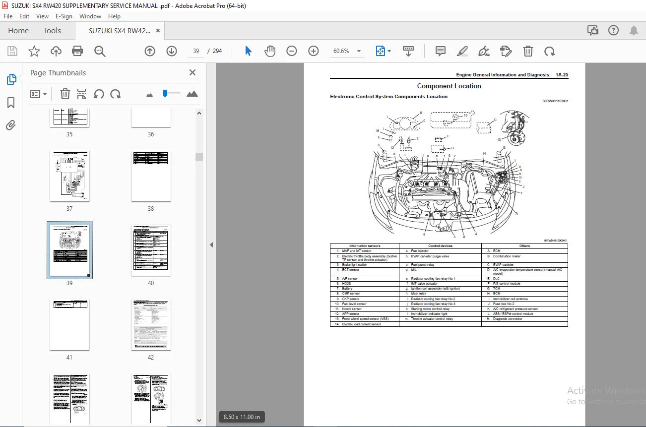
TOP.......................................................................................................................................................  0
MANUAL LIST...............................................................................................................................................  0
IMPORTANT.................................................................................................................................................  1
FOREWORD..................................................................................................................................................  3
TABLE OF CONTENTS.........................................................................................................................................  5
Precautions...............................................................................................................................................  7
	Precautions...........................................................................................................................................  8
		Precautions.......................................................................................................................................  8
			Precaution for Vehicle Equipped with ESP‚ System..............................................................................................  8
General Information.......................................................................................................................................  9
	General Information................................................................................................................................... 10
		General Description............................................................................................................................... 10
			Abbreviations................................................................................................................................. 10
Engine.................................................................................................................................................... 13
	Engine General Information and Diagnosis.............................................................................................................. 15
		Precautions....................................................................................................................................... 15
			Precautions on Engine Service................................................................................................................. 15
			Precautions in Diagnosing Trouble............................................................................................................. 15
			Precautions for DTC Troubleshooting........................................................................................................... 16
			Precautions of ECM Circuit Inspection......................................................................................................... 16
			Precautions of Electric Throttle Body System Calibration...................................................................................... 16
			Precaution on CAN Troubleshooting............................................................................................................. 17
		General Description............................................................................................................................... 19
			Statement on Cleanliness and Care............................................................................................................. 19
			Engine Diagnosis General Description.......................................................................................................... 19
			On-Board Diagnostic System Description........................................................................................................ 19
			DLC (Data Link Connector)..................................................................................................................... 21
			Engine and Emission Control System Description................................................................................................ 21
			CAN Communication System Description.......................................................................................................... 22
			Air Intake System Description................................................................................................................. 24
			Description of Electric Throttle Body System.................................................................................................. 25
			Description of Electric Throttle Body System Calibration...................................................................................... 26
			Generator Control System Description.......................................................................................................... 26
			A/F Sensor Description........................................................................................................................ 27
			Electronic Control System Description......................................................................................................... 28
			Engine and Emission Control Input / Output Table.............................................................................................. 33
		Schematic and Routing Diagram..................................................................................................................... 37
			Engine and Emission Control System Diagram.................................................................................................... 37
		Component Location................................................................................................................................ 39
			Electronic Control System Components Location................................................................................................. 39
		Diagnostic Information and Procedures............................................................................................................. 40
			Engine and Emission Control System Check...................................................................................................... 40
			Malfunction Indicator Lamp (MIL) Check........................................................................................................ 43
			DTC Check..................................................................................................................................... 44
			DTC Clearance................................................................................................................................. 45
			Troubleshooting for Communication Error with Scan Tool Using CAN.............................................................................. 45
			DTC Table..................................................................................................................................... 50
			Fail-Safe Table............................................................................................................................... 54
			Scan Tool Data................................................................................................................................ 56
			Visual Inspection............................................................................................................................. 61
			Engine Basic Inspection....................................................................................................................... 62
			Engine Symptom Diagnosis...................................................................................................................... 63
			MIL Does Not Come ON with Ignition Switch ON and Engine Stop (but Engine Can Be Started)...................................................... 70
			MIL Remains ON after Engine Starts............................................................................................................ 72
			DTC P0031 / P0032: HO2S Heater Control Circuit Low / High (Sensor-1, Bank-1).................................................................. 73
			DTC P0037 / P0038: HO2S Heater Control Circuit Low / High (Sensor-2, Bank-1).................................................................. 76
			DTC P0102 / P0103: Mass or Volume Air Flow Circuit Low / High Input........................................................................... 78
			DTC P0112 / P0113: Intake Air Temperature Sensor Circuit Low / High Input..................................................................... 80
			DTC P0117 / P0118: Engine Coolant Temperature Circuit Low / High.............................................................................. 81
			DTC P0122 / P0123: Throttle / Pedal Position Sensor / Switch “A” Circuit Low / High........................................................... 83
			DTC P0131 / P0132: O2 Sensor Circuit Low Voltage / High Voltage (Sensor-1, Bank-1)............................................................ 85
			DTC P0134: O2 Sensor Circuit No Activity Detected (Sensor-1, Bank-1).......................................................................... 86
			DTC P0140: O2 Sensor (HO2S) Circuit No Activity Detected (Sensor-2, Bank-1)................................................................... 88
			DTC P0171 / P0172: System Too Lean / Too Rich (Sensor-1, Bank-1).............................................................................. 89
			DTC P0222 / P0223: Throttle Position Sensor (Sub) Circuit Low / High.......................................................................... 91
			DTC P0327 / P0328: Knock Sensor Circuit Low / High............................................................................................ 93
			DTC P0335: Crankshaft Position Sensor “A” Circuit............................................................................................. 94
			DTC P0340: Camshaft Position Sensor “A” Circuit............................................................................................... 96
			DTC P0350: Ignition Coil Primary / Secondary Circuit.......................................................................................... 98
			DTC P0443: EVAP Emission System Purge Control Valve Circuit...................................................................................100
			DTC P0462 / P0463: Fuel Level Sensor Circuit Low / High.......................................................................................102
			DTC P0480: Fan 1 Control Circuit..............................................................................................................104
			DTC P0481: Fan 2 Control Circuit..............................................................................................................107
			DTC P0500: Vehicle Speed Sensor “A”...........................................................................................................109
			DTC P0532 / P0533: A/C Refrigerant Pressure Sensor Circuit Low / High.........................................................................110
			DTC P0601 / P0602 / P0607: Internal Control Module Memory Check Sum Error / Control Module Programming Error / Control Module Performance.....112
			DTC P0620: Generator Control Circuit..........................................................................................................113
			DTC P0625 / P0626: Generator Field Terminal Circuit Low / High................................................................................115
			DTC P0660 / P0662: Intake Manifold Tuning Valve Control Circuit Open / High...................................................................117
			DTC P1501 / P1502: Electric Load Current Sensor Circuit Low / High............................................................................119
			DTC P1510: ECM Back-Up Power Supply Malfunction...............................................................................................121
			DTC P2101: Throttle Actuator Control Motor Circuit Range / Performance........................................................................122
			DTC P2102: Throttle Actuator Control Motor Circuit Low........................................................................................123
			DTC P2103: Throttle Actuator Control Motor Circuit High.......................................................................................124
			DTC P2111: Throttle Actuator Control System - Stuck Open......................................................................................125
			DTC P2119: Throttle Actuator Control Throttle Body Range / Performance........................................................................125
			DTC P2122 / P2123: Throttle / Pedal Position Sensor / Switch “D” Circuit Low / High...........................................................127
			DTC P2127 / P2128: Throttle / Pedal Position Sensor / Switch “E” Circuit Low / High Input.....................................................129
			DTC P2135: Throttle / Pedal Position Sensor / Switch “A” / “B” Voltage Correction.............................................................131
			DTC P2138: Pedal Position Sensor (Main / Sub) Voltage Correction..............................................................................132
			DTC P2228 / P2229: Barometric Pressure Circuit Low / High.....................................................................................133
			DTC U0073: Control Module Communication Bus Off...............................................................................................133
			DTC U0101: Lost Communication with TCM........................................................................................................133
			DTC U0121: Lost Communication with ABS / ESP‚ Control Module..................................................................................133
			DTC U0140: Lost Communication with Body Control Module........................................................................................133
			Troubleshooting for CAN-DTC...................................................................................................................134
			Inspection of ECM and Its Circuits............................................................................................................139
			ECM Power and Ground Circuit Check............................................................................................................158
			Fuel Injector Circuit Check...................................................................................................................162
			Fuel Pump and Its Circuit Check...............................................................................................................164
			Fuel Pressure Check...........................................................................................................................167
			A/C Condenser Cooling Fan Control System Inspection...........................................................................................169
			A/C System Circuits Check.....................................................................................................................171
			Electric Load Signal Circuit Check............................................................................................................174
			Radiator Cooling Fan Low Speed Control System Check...........................................................................................176
			Radiator Cooling Fan High Speed Control System Check..........................................................................................178
		Repair Instructions...............................................................................................................................179
			Idle Speed and IAC Throttle Valve Opening Inspection..........................................................................................179
		Special Tools and Equipment.......................................................................................................................180
			Special Tool..................................................................................................................................180
	Engine Electrical Devices.............................................................................................................................181
		Repair Instructions...............................................................................................................................181
			Electric Load Current Sensor On-Vehicle Inspection............................................................................................181
	Charging System.......................................................................................................................................182
		General Description...............................................................................................................................182
			Generator Description.........................................................................................................................182
Suspension................................................................................................................................................185
	Suspension General Diagnosis..........................................................................................................................186
		Specifications....................................................................................................................................186
			Wheel Alignment Specifications................................................................................................................186
	Wheels and Tires......................................................................................................................................187
		Specifications....................................................................................................................................187
			Wheels and Tires Specifications...............................................................................................................187
			Tightening Torque Specifications..............................................................................................................187
Brakes....................................................................................................................................................189
	Brake Control System and Diagnosis....................................................................................................................191
		General Description...............................................................................................................................191
			Front Brake Hose / Pipe Construction..........................................................................................................191
		Diagnostic Information and Procedures.............................................................................................................192
			Brakes Symptom Diagnosis......................................................................................................................192
		Repair Instructions...............................................................................................................................194
			Master Cylinder Removal and Installation......................................................................................................194
		Specifications....................................................................................................................................195
			Tightening Torque Specifications..............................................................................................................195
	Electronic Stability Program..........................................................................................................................196
		Precautions.......................................................................................................................................196
			Precautions in Diagnosing Troubles............................................................................................................196
			Precautions in On-Vehicle Service.............................................................................................................196
			Precautions in Hydraulic Unit Operation Check.................................................................................................196
			Precautions in Sensor Calibration.............................................................................................................196
			Precautions in Speedometer Test or Other Tests................................................................................................197
		General Description...............................................................................................................................197
			Electronic Stability Program Description......................................................................................................197
			ESP‚ Hydraulic Unit / Control Module Assembly Description.....................................................................................197
			Warning Light, Indicator Light Description....................................................................................................198
			CAN Communication System Description..........................................................................................................199
		Schematic and Routing Diagram.....................................................................................................................200
			Electronic Stability Program Schematic........................................................................................................200
			Electronic Stability Program Wiring Circuit Diagram...........................................................................................201
		Component Location................................................................................................................................202
			Electronic Stability Program Component Location...............................................................................................202
		Diagnostic Information and Procedures.............................................................................................................204
			Electronic Stability Program Check............................................................................................................204
			ESP‚ Warning Light Check......................................................................................................................206
			ABS Warning Lamp Check........................................................................................................................206
			EBD Warning Lamp (Brake Warning Lamp) Check...................................................................................................206
			DTC Check.....................................................................................................................................207
			DTC Table.....................................................................................................................................207
			DTC Clearance.................................................................................................................................210
			Fail-Safe Table...............................................................................................................................211
			Scan Tool Data................................................................................................................................213
			ESP‚ Warning Light Does Not Come ON at Ignition Switch ON.....................................................................................215
			ESP‚ Warning Light Comes ON Steady............................................................................................................216
			ABS Warning Lamp Does Not Come ON at Ignition Switch ON.......................................................................................217
			ABS Warning Lamp Comes ON Steady..............................................................................................................217
			EBD Warning Lamp (Brake Warning Lamp) Comes ON Steady.........................................................................................218
			Serial Data Link Circuit Check................................................................................................................220
			DTC C1016: Brake Light Switch.................................................................................................................222
			DTC C1017 / C1023: Lateral G Sensor / Yaw Rate Sensor.........................................................................................224
			DTC C1020 / C1028: Master Cylinder Pressure Sensor Power Supply Failure / Circuit.............................................................224
			DTC C1021 / C1022 / C1025 / C1026 / C1031 / C1032 / C1035 / C1036: Wheel Speed Sensor Circuit / Sensor or Encoder.............................225
			DTC C1024: Steering Angle Sensor..............................................................................................................227
			DTC C1027: ESP‚ OFF Switch....................................................................................................................227
			DTC C1033: Wheel Speed Sensor Deviation.......................................................................................................228
			DTC C1034 / C1039: Yaw Rate / G Sensor Power Supply Failure / Internal Failure................................................................230
			DTC C1037: Steering Angle Sensor Power Supply Failure.........................................................................................231
			DTC C1038: Steering Angle Sensor Detect Rolling Counter.......................................................................................232
			DTC C1040: ESP‚ Continuous Operation..........................................................................................................233
			DTC C1041 / C1042 / C1043 / C1044 / C1045 / C1046 / C1051 / C1052 / C1053 / C1054 / C1055 / C1056: Inlet / Outlet / Cut / Suction Solenoid....233
			DTC C1057: Power Supply Voltage Too High / Too Low............................................................................................235
			DTC C1061: Pump Motor Circuit.................................................................................................................236
			DTC C1063: Solenoid Valve Power Supply Driver Circuit.........................................................................................237
			DTC C1071: Control Module Internal Defect.....................................................................................................238
			DTC C1075: Steering Angle Sensor Calibration..................................................................................................238
			DTC C1091: CAN Invalid Data from ECM..........................................................................................................239
			DTC C1096: Yaw Rate / G Sensor Message Counter Error..........................................................................................239
			DTC U0073: Control Module Communication Bus Off...............................................................................................240
			DTC U0100: Lost Communication with ECM / PCM..................................................................................................240
			DTC U0101 Lost Communication with TCM.........................................................................................................240
			DTC U0114 Lost Communication with Four-Wheel Drive Clutch Control Module......................................................................240
			DTC U0123 Lost Communication with Yaw Rate Sensor Module......................................................................................240
			DTC U0126: Lost Communication with Steering Angle Sensor......................................................................................240
			ESP‚ Hydraulic Unit / Control Module Assembly Power and Ground Circuit Check..................................................................240
		Repair Instructions...............................................................................................................................242
			ESP‚ Hydraulic Unit Operation Check...........................................................................................................242
			Sensor Calibration............................................................................................................................243
			ESP‚ Hydraulic Unit / Control Module Assembly On-Vehicle Inspection...........................................................................243
			ESP‚ Hydraulic Unit / Control Module Assembly Removal and Installation........................................................................244
			Front Wheel Speed Sensor On-Vehicle Inspection................................................................................................245
			Front Wheel Speed Sensor Removal and Installation.............................................................................................245
			Front Wheel Speed Sensor Inspection...........................................................................................................245
			Rear Wheel Speed Sensor On-Vehicle Inspection.................................................................................................245
			Rear Wheel Speed Sensor Removal and Installation..............................................................................................245
			Rear Wheel Speed Sensor Inspection............................................................................................................245
			Front Wheel Speed Sensor Encoder On-Vehicle Inspection........................................................................................245
			Front Wheel Speed Sensor Encoder Removal and Installation.....................................................................................245
			Rear Wheel Speed Sensor Encoder On-Vehicle Inspection.........................................................................................245
			Rear Wheel Speed Sensor Encoder Removal and Installation......................................................................................245
			Master Cylinder Pressure Sensor On-Vehicle Inspection.........................................................................................246
			Yaw Rate / G Sensor On-Vehicle Inspection.....................................................................................................246
			Yaw Rate / G Sensor Removal and Installation..................................................................................................248
			Yaw Rate / G Sensor Inspection................................................................................................................248
			Steering Angle Sensor On-Vehicle Inspection...................................................................................................248
			Steering Angle Sensor Removal and Installation................................................................................................249
			Steering Angle Sensor Inspection..............................................................................................................250
			ESP‚ OFF Switch Removal and Installation......................................................................................................250
			ESP‚ OFF Switch Inspection....................................................................................................................250
		Specifications....................................................................................................................................251
			Tightening Torque Specifications..............................................................................................................251
		Special Tools and Equipment.......................................................................................................................251
			Special Tool..................................................................................................................................251
Restraint.................................................................................................................................................253
	Air Bag System........................................................................................................................................254
		Diagnostic Information and Procedures.............................................................................................................254
			DTC Table.....................................................................................................................................254
Body, Cab and Accessories.................................................................................................................................259
	Instrumentation / Driver Info. / Horn.................................................................................................................260
		General Description...............................................................................................................................260
			CAN Communication System Description..........................................................................................................260
		Schematic and Routing Diagram.....................................................................................................................261
			Combination Meter Circuit Diagram.............................................................................................................261
	Glass / Windows / Mirrors.............................................................................................................................263
		Diagnostic Information and Procedures.............................................................................................................263
			Deicer Symptom Diagnosis......................................................................................................................263
		Repair Instructions...............................................................................................................................263
			Rear End Door Window Defogger Relay Inspection................................................................................................263
			Deicer Switch Inspection......................................................................................................................263
			Deicer Relay Inspection.......................................................................................................................264
			Deicer Wire Inspection........................................................................................................................264
			Deicer Wire Repair............................................................................................................................264
			Power Door Mirror Switch Inspection...........................................................................................................264
			Power Door Mirror Actuator Inspection.........................................................................................................265
	Seats.................................................................................................................................................266
		Diagnostic Information and Procedures.............................................................................................................266
			Front Seat Heater Symptom Diagnosis...........................................................................................................266
		Repair Instructions...............................................................................................................................267
			Front Seat Components.........................................................................................................................267
			Front Seat Removal and Installation...........................................................................................................268
			Front Seat Heater Switch (Driver and Passenger Side) Inspection...............................................................................268
			Front Seat Heater Wire Inspection.............................................................................................................268
			Rear Seat Components..........................................................................................................................269
		Specifications....................................................................................................................................270
			Tightening Torque Specifications..............................................................................................................270
		Special Tools and Equipment.......................................................................................................................270
			Recommended Service Material..................................................................................................................270
Control Systems...........................................................................................................................................271
	Body Electrical Control System........................................................................................................................272
		Precautions.......................................................................................................................................272
			Precautions in Diagnosing Trouble.............................................................................................................272
		General Description...............................................................................................................................272
			BCM General Description.......................................................................................................................272
			Security Alarm Description (If Equipped)......................................................................................................272
		Schematic and Routing Diagram.....................................................................................................................273
			Body Electrical Control System Wiring Circuit Diagram.........................................................................................273
			Connector Layout Diagram of BCM and Junction Block............................................................................................276
		Component Location................................................................................................................................277
			BCM and Related System Component Location.....................................................................................................277
		Diagnostic Information and Procedures.............................................................................................................278
			BCM Self-Diagnosis Function...................................................................................................................278
			Scan Tool Data................................................................................................................................280
			Inspection of BCM and Its Circuits............................................................................................................282
		Repair Instructions...............................................................................................................................290
			Security Alarm Mode Selection Procedure (If Equipped).........................................................................................290
	Keyless Start System..................................................................................................................................291
		Schematic and Routing Diagram.....................................................................................................................291
			Keyless Start System Electric Wiring Circuit Diagram..........................................................................................291
		Diagnostic Information and Procedures.............................................................................................................292
			Precautions in Diagnosing Troubles............................................................................................................292
			Door Lock Operation (Keyless Start System)....................................................................................................292
COPYRIGHT.................................................................................................................................................293
BOOKCOVER.................................................................................................................................................294
S.S