
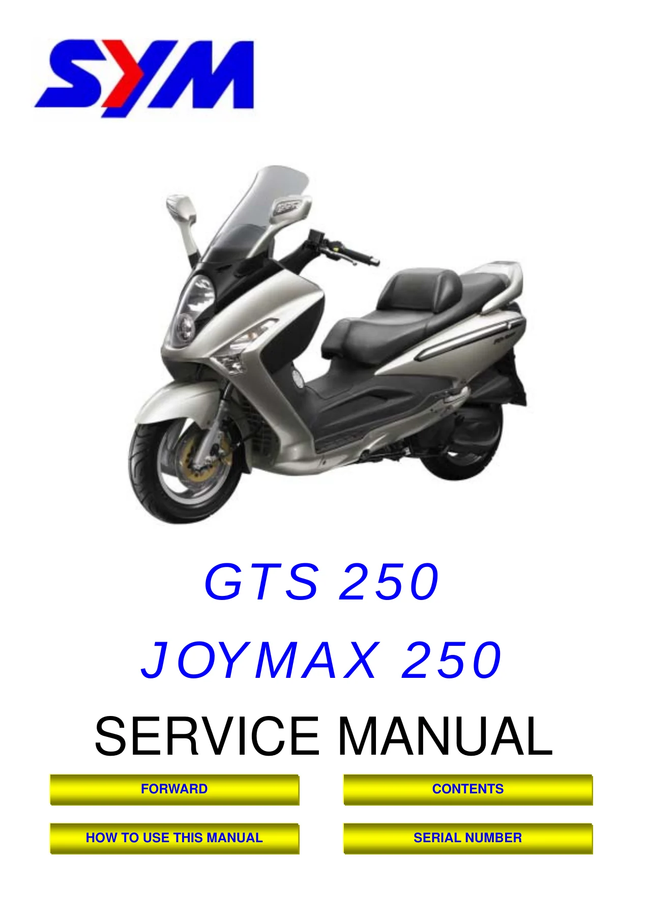
SYM GTS 250 Joymax 250 Scooter Service Manual PDF – LM25W Series Workshop Guide
Original price was: $34.95.$22.95Current price is: $22.95.
Complete 217-page SANYANG service manual for the SYM GTS 250 and Joymax 250 (LM25W series) scooter, covering engine, fuel, lubrication, cooling, CVT drive, brakes, steering, suspension, bodywork and full electrical system.
Description
SYM GTS 250 Joymax 250 Service Manual – LM25W Series
This is the full SANYANG service manual for the GTS 250 and Joymax 250 scooter, built on the LM25W series platform. Published by SANYANG INDUSTRY CO., LTD. Service Department, it is the technical reference used by technicians for component inspection, repair and adjustment across the whole machine. Every chapter is written around three practical pillars – Service Procedures, Operation Key Points and Inspection Adjustment – so you get the exact sequence and the exact value, not just a description of the part.
The SYM GTS 250 Joymax 250 service manual is delivered as an instant-download PDF. It runs to 217 pages across 18 numbered chapters, from general information and torque values through to the final wiring diagram.
File Details
- Manual type: Service Manual (workshop / repair)
- Brand / manufacturer: SANYANG INDUSTRY CO., LTD. (SYM)
- Model series: LM25W
- Marketing names: GTS 250 / Joymax 250
- Language: English
- Page count: 217 pages
- File format: PDF
Chapters Covered
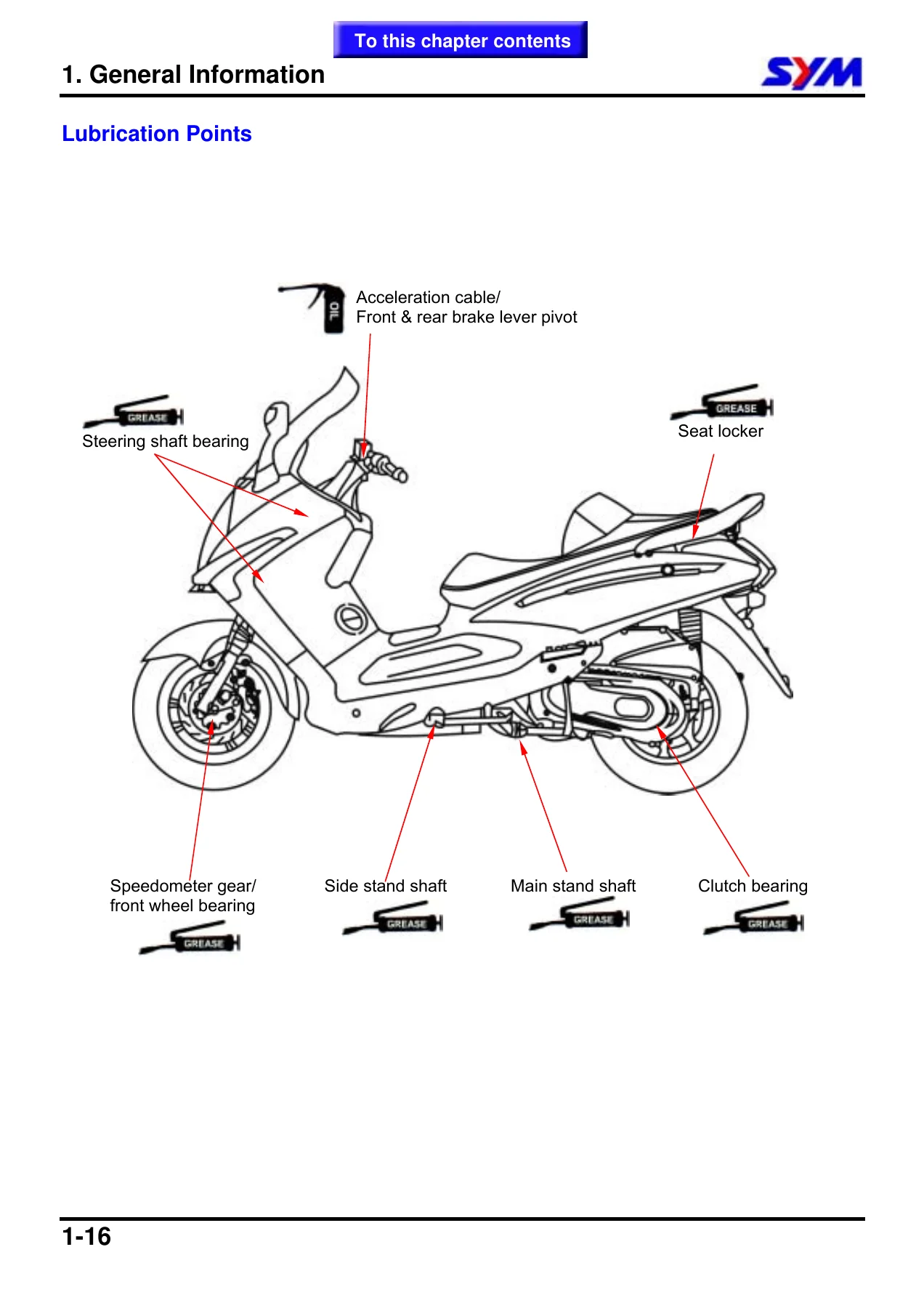
- 1. General Information – symbols and marks, general safety, service precautions, specifications, torque values (standard, engine and frame), trouble diagnosis flow charts, lubrication points
- 2. Service Maintenance Information – periodical maintenance schedule, engine oil and strainer, gear oil, fuel lines / cable, air cleaner, P.C.V. system, valve clearance, carburetor idle speed, ignition system, spark plug, cylinder compression, drive belt, steering head bearing, cushions, disc brake system, brake light / starting inhibitor switch, headlight beam, wheel / tire, battery, nut and bolt tightness
- 3. Lubrication System – mechanism diagram, oil strainer clean, engine oil, oil pump removal / disassembly / inspection / re-assembly / installation, gear oil
- 4. Fuel System – carburetor removal and install, vacuum chamber, air cut-off valve, automatic by-starter, float chamber, idle speed adjustment, fuel tank, fuel pump, air cleaner
- 5. Removal & Installation of Engine – engine removal, engine hanger, rear fork, engine bush removal, engine installation
- 6. Cylinder Head / Valve – cylinder head removal, disassembly, inspection, valve stem replacement, valve seat inspection and service, cylinder head reassembly and installation, valve clearance adjustment
- 7. Cylinder / Piston – cylinder and piston removal, inspection, piston ring installation, piston installation, cylinder installation
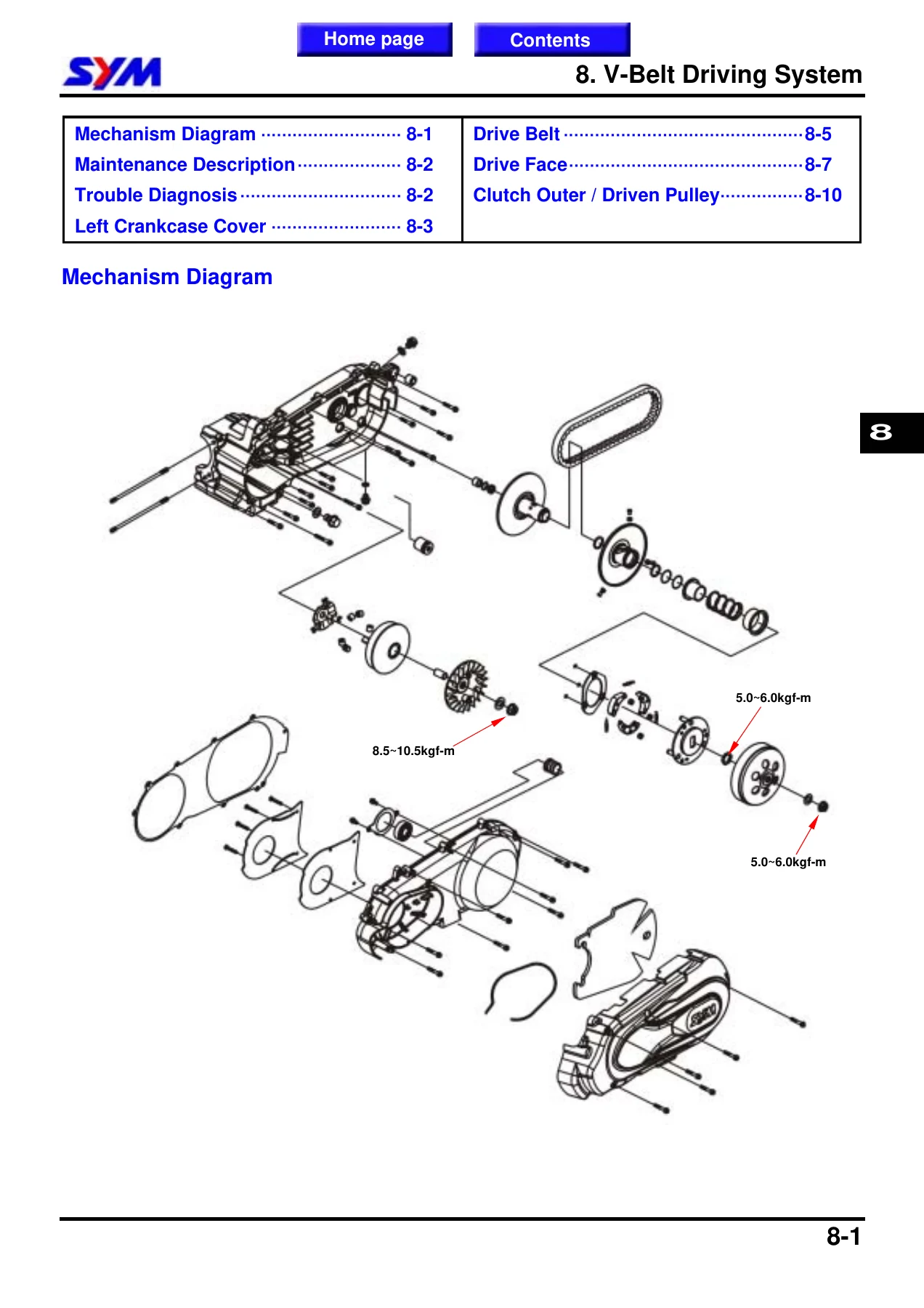
- 8. V-Belt Driving System / Kick-Starter – left crankcase cover, drive belt, drive face, clutch outer / driven pulley, clutch weight replacement, driven pulley bearing
- 9. Final Driving Mechanism – disassembly, inspection, bearing replacement, re-assembly of the final drive
- 10. Alternator / Starting Clutch – right crankcase cover removal, A.C.G. set removal, right cover bearing, flywheel removal, starting clutch, A.C.G. flywheel and set installation
- 11. Crankcase / Crank – crankcase disassembly, crankshaft inspection, crankcase assembly
- 12. Cooling System – coolant change, radiator, water pump, thermostat, troubleshooting chart
- 13. Body Cover – handle cover, front cover, meter panel, inner box, side cover, front under spoiler, rear carrier, luggage box, rear body cover, floor panel, front fender, rear fender
- 14. Brake System – disc brake system inspection, brake fluid adding and replacement / air-bleed, front and rear brake calipers, brake pad replacement, brake disk, master cylinder
- 15. Steering / Front Wheel / Front Cushion – steering handle, front wheel, front cushion, steering stem
- 16. Rear Wheel / Rear Fork / Rear Cushion – muffler, rear wheel, rear fork, rear cushion
- 17. Electrical System – battery, fuse circuit, charging system, ignition system, starting system, meters, lights and bulbs, switches and horn, fuel unit, cooling fan thermo switch, thermo sensor, water temperature meter
- 18. Electrical Diagram – LM25W full wiring diagram
What makes this SYM GTS 250 Joymax 250 service manual genuinely useful is the way it moves between theory and shop floor. The early diagnostic charts trace a fault – hard starting, poor performance, misfire, clutch shudder, brake drag – down to the specific component at fault, and every later chapter then tells you how to remove that component, inspect it against a printed service limit, and install it to a printed torque figure. Torque tables appear at the top of the relevant chapter in both engine and frame categories, so you are never working from memory.
Engine, Drive and Chassis Coverage
The engine chapters deal with the LM25W single-cylinder, four-stroke unit from the top down: cylinder head and valve train, valve stem and valve seat service, cylinder and piston measurements, camshaft and rocker arm inspection, then crankcase split and crankshaft run-out checks. The drive chapters cover the complete CVT chain – drive face, weight rollers, drive belt width limit, clutch outer, clutch weights, driven pulley, spring free length – before moving into the final reduction gearbox and its bearing replacement.
On the chassis side, the SYM GTS 250 Joymax 250 repair manual covers the front and rear disc brake circuits with caliper and master cylinder service, air bleeding and brake pad wear limits, the steering stem with cone race and ball bearing installation, front and rear cushions, both wheels and the rear fork bearing. The body cover chapter lays out the exact strip-down sequence so you can get at the hidden fasteners without cracking clips or bending hooks.
Electrical System and Wiring Diagram
Chapter 17 is a self-contained electrical section – battery removal and charging rates, the fuse box layout and what each fuse feeds, charging circuit and regulator rectifier checks, ignition circuit, starter relay and starter motor, meter circuits, headlight and winker bulb replacement, switch continuity tables, horn, fuel unit resistance values, cooling fan thermo switch test and thermo sensor resistance against temperature. Chapter 18 finishes the manual with the full LM25W electrical diagram.
What This Manual Lets You Do
With this SYM GTS 250 Joymax 250 service manual you can carry out scheduled maintenance to the printed intervals, diagnose a no-start or poor-running complaint through the flow charts, set valve clearance and idle speed, rebuild the top end, replace the drive belt and rollers, service both brake circuits, chase a charging fault through the regulator rectifier and A.C.G., and strip the bodywork in the correct order. Because the SYM GTS 250 Joymax 250 workshop guide gives capacities, clearances, service limits and tightening torques for the LM25W machine specifically, you avoid the two most expensive mistakes on a scooter like this – over-torquing small fasteners and reusing a part that is already past its wear limit.
IMAGES PREVIEW
The file is an instant PDF download. There is no shipping and nothing to wait for – the manual is on your screen in minutes and prints cleanly if you prefer a paper copy in the workshop. It opens on a laptop, tablet or phone, so you can keep the relevant chapter beside the bike while you work.
Reviews
There are no reviews yet.