
T55-L-712 Gas Turbine Engine TM 55-2840-254-23-4 Aviation Maintenance Manual Volume 4
Original price was: $34.95.$20.95Current price is: $20.95.
1,016-page factory-format U.S. Army technical manual TM 55-2840-254-23-4 (26 April 1983) for the T55-L-712 gas turbine engine, covering fuel, electrical/ignition, lubrication, and torquemeter system maintenance. Instant PDF download.
Description
T55-L-712 Gas Turbine Engine Aviation Maintenance Manual (TM 55-2840-254-23-4)
This is the complete T55-L-712 Gas Turbine Engine Aviation Unit and Aviation Intermediate Maintenance Manual, published by Headquarters, Department of the Army as TM 55-2840-254-23-4, dated 26 April 1983 (NSN 2840-01-030-4890). Covering the T55-L-712 engine used in Army rotary-wing aircraft, this Aviation Maintenance Manual Volume 4 delivers the fuel, electrical/ignition, lubrication, and torquemeter system maintenance instructions in one instantly downloadable PDF.
File Details
- Manual type: Aviation Unit and Aviation Intermediate Maintenance Manual (Technical Manual)
- Brand/Engine: T55-L-712 Gas Turbine Engine
- Document number: TM 55-2840-254-23-4
- Publication date: 26 April 1983 (incorporates Changes 1 through 8)
- NSN: 2840-01-030-4890
- Language: English
- Page count: 1,016 pages
- File format: PDF
Chapters Covered
- Chapter 6 — Fuel System Maintenance Instructions
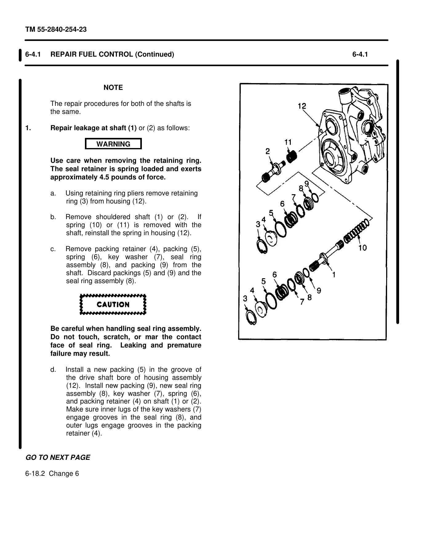
- Section I: Fuel Control – Remove, Disassemble, Clean, Inspect, Repair, Assemble, Install
- Section II: Fuel Control – Preparation for Storage or Shipment
- Section III: Fuel Boost Pump Assembly – Maintenance Procedures
- Section IV: Fuel Boost Pump Assembly – Preparation for Storage or Shipment
- Section V: Left- and Right-Hand Fuel Manifold Assemblies
- Section VI: Primer Tube Assembly
- Section VII: Start Fuel Nozzles
- Section VIII: Main Fuel Filter and Bracket
- Section IX: In-Line Fuel Filter Assembly
- Section X: Flow Divider and Bracket
- Section XI: Fuel Check Valve
- Section XII: Starting Fuel Solenoid Valve
- Section XIII: Fuel Lines – Hose and Tube Assemblies
- Chapter 7 — Electrical and Ignition Systems Maintenance Instructions
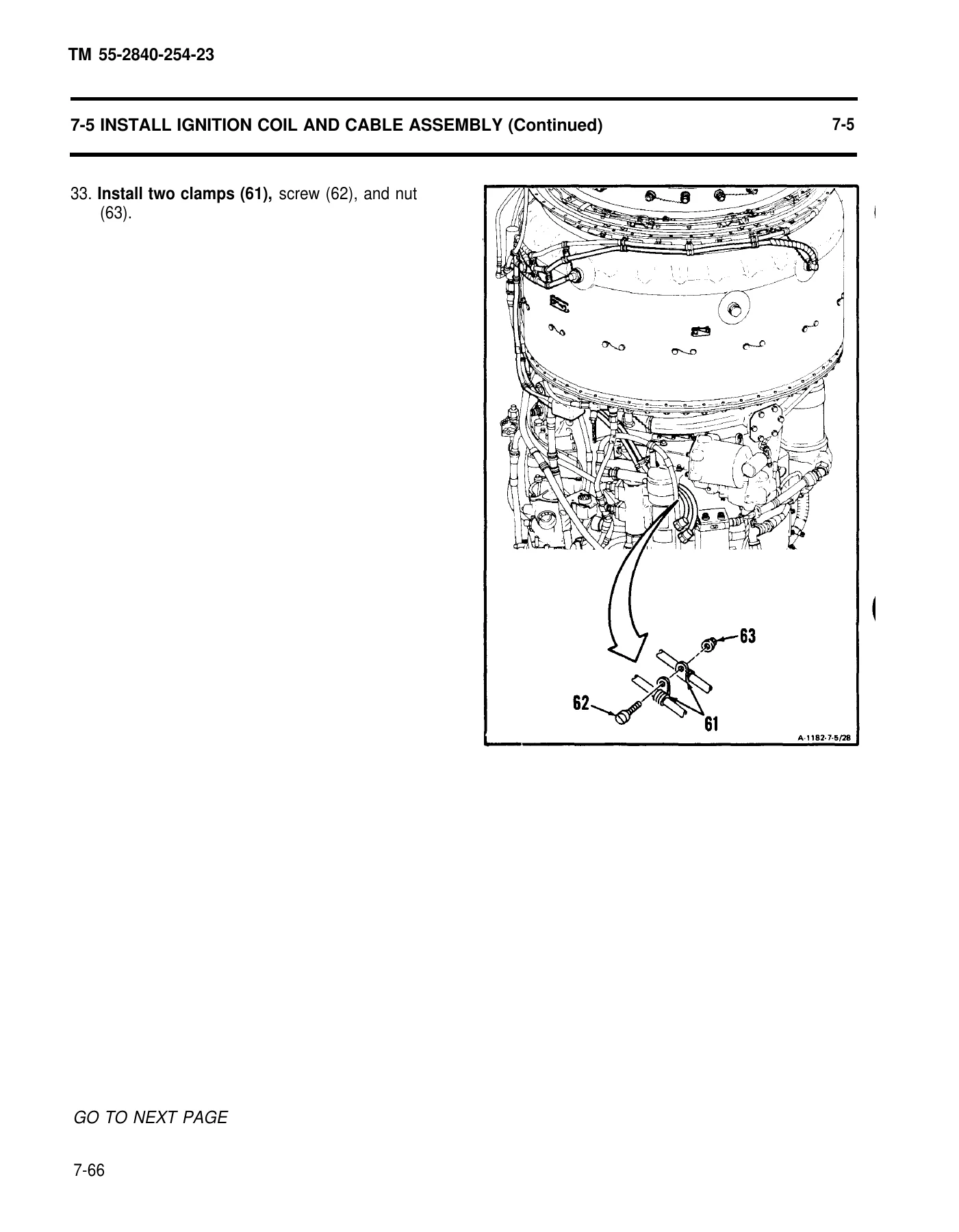
- Section I: Ignition Coil and Cable Assembly
- Section II: Spark Igniters
- Section III: Ignition Exciter
- Section IV: Main Electrical Cable Assembly (Nine and Six Connector variants)
- Chapter 8 — Lubrication System Maintenance Instructions
- Section I: Main Oil Pump and Scavenge Oil Screen, Oil Pump Check Valve
- Section II: Oil Cooler Assembly
- Section III: Oil Temperature Transmitter
- Section IV: Oil Filler Assembly and Oil Filler Strainer
- Section V: Oil Filter Cap and Stem Assembly and Oil Filter Element
- Section VI: Dual Chip Detector
- Section VII: Oil Lines – Hose and Tube Assemblies
- Section VIII: Starter Gearbox Filter
- Section IX: No. 2 Bearing Pressure Oil Strainer
- Section X: No. 4 and 5 Bearing Filter
- Section XI: Oil Drain Cock
- Section XII: Chip Detector
- Section XIII: Oil Level Indicator
- Section XIV: Oil Level Float Assembly
- Chapter 9 — Torquemeter System Maintenance Instructions
- Section I: Torquemeter Junction Box
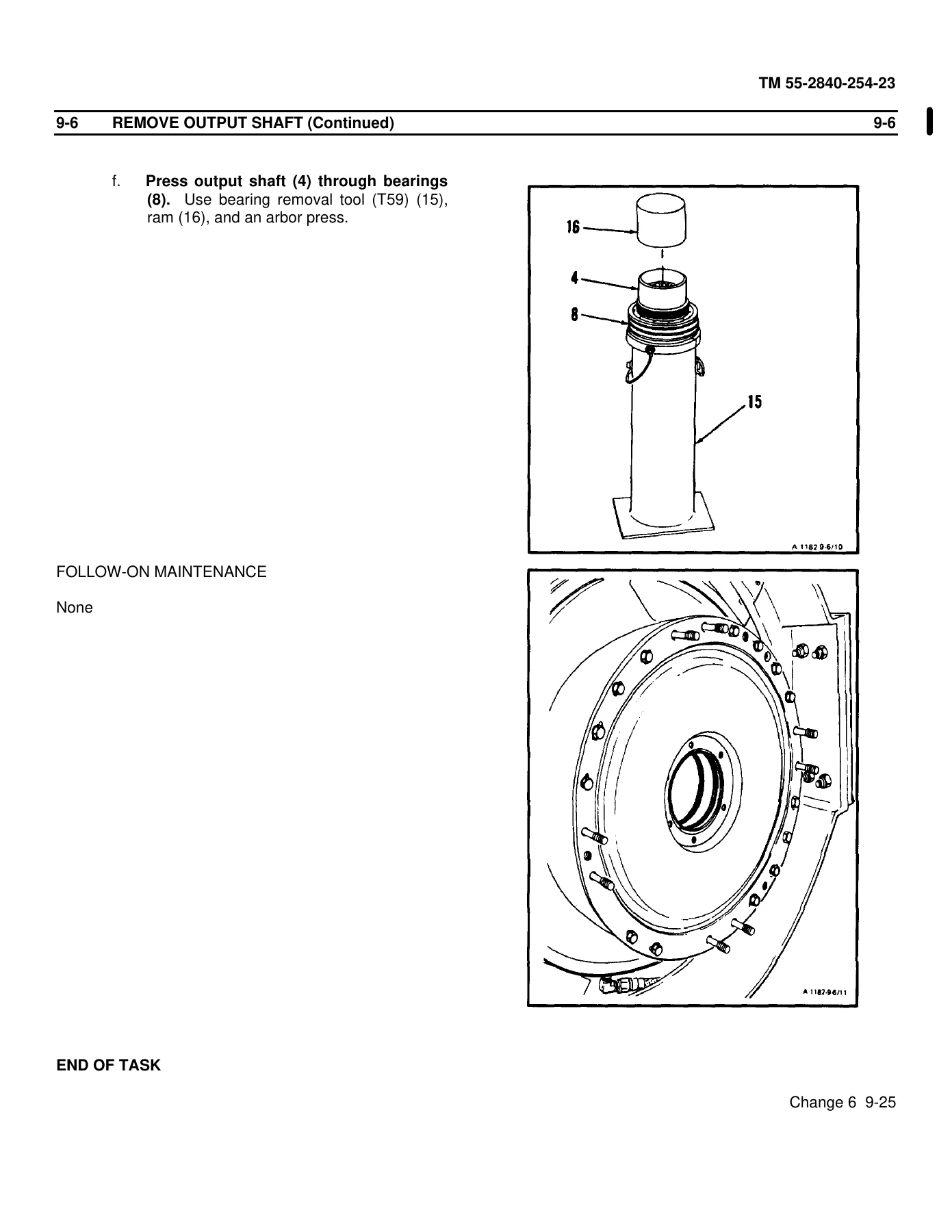
- Section II: Output Shaft
- Section III: Torquemeter Head Assembly
IMAGES PREVIEW


- Appendix A — References
- Appendix C — Expendable Supplies and Materials List
- Appendix D — Wiring Diagrams (Electrical System Schematic)
- Appendix E — Illustrated List of Manufactured Items
- Glossary and Subject Index
Together these chapters give an AVUM/AVIM-level powerplant technician everything needed to remove, disassemble, clean, inspect, repair, assemble, install, and preserve the major fuel, ignition, lubrication, and torquemeter components of the T55-L-712 engine, with initial setup tables listing required tools, materials, parts, and personnel for every task.
What This T55-L-712 Manual Enables
With this T55-L-712 Gas Turbine Engine Aviation Maintenance Manual you can perform factory-sequence removal, disassembly, cleaning, inspection, repair, and reassembly of the fuel control, fuel boost pump, fuel manifolds, ignition coil and cable assembly, spark igniters, ignition exciter, main electrical cable assemblies, oil pump, oil cooler, oil filters, chip detectors, oil level indicator, and the complete torquemeter junction box, output shaft, and head assembly. Every task includes the exact tools, materials, and torque-critical steps called out by the original Army technical manual, helping you avoid the guesswork and mismatched aftermarket instructions that lead to costly rework or safety-critical part failures.
This TM 55-2840-254-23-4 manual downloads instantly as a PDF after purchase — no shipping, no waiting. Use it on a phone, tablet, laptop, or shop PC, and print any page you need at the bench.
Reviews
There are no reviews yet.