
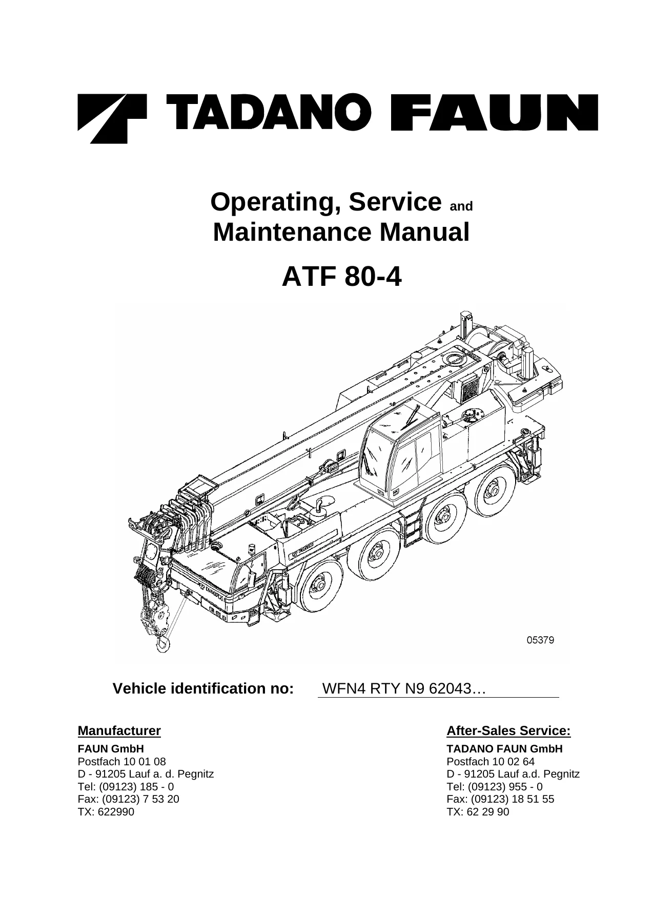
Tadano Faun ATF 80-4 Operating, Service and Maintenance Manual – PDF Download
Original price was: $42.95.$24.95Current price is: $24.95.
Complete English operating, service and maintenance manual for the Tadano Faun ATF 80-4 all-terrain mobile crane, covering chassis and superstructure, technical data, maintenance schedules, hydraulic and wiring diagrams, load charts, testing instructions and troubleshooting in a single 882-page PDF.
Description
The Tadano Faun ATF 80-4 Operating, Service and Maintenance Manual is the complete documentation set for the ATF 80-4 all-terrain mobile crane, following the machine from daily operation through scheduled servicing and fault diagnosis. It is not a single-section handbook: the file combines operating instructions, service and maintenance procedures, circuit and piping diagrams, crane testing instructions, troubleshooting tables and a manufacturer annex covering the ZF gearbox and the PAT DS 350 automatic safe load indicator.
Written in English and running to roughly 882 pages, the Tadano Faun ATF 80-4 Operating, Service and Maintenance Manual is aimed at the crane operator, the workshop technician and the maintenance planner. Because the ATF 80-4 is a carrier and a crane on one chassis, the documentation is duplicated and clearly labelled throughout: Part B1 and Part C1 deal with the chassis, while Part B2 and Part C2 cover the superstructure. Everything needed for safe daily operation, planned servicing and fault finding sits in one place.
File Details
- Manual type: Operating, Service and Maintenance Manual
- Brand: Tadano Faun
- Model: ATF 80-4
- Vehicle identification number (example): WFN4 RTY N9 62043…
- Language: English
- Page count: 882 pages
- File format: PDF
- Parts included: A (Technical Details), B (Operating Instructions), C (Service and Maintenance), D (Circuit and Piping Diagrams), E (Crane Testing Instructions), F (Troubleshooting), G (Annex)
Chapters Covered
- How to use this Operating Manual
- Mounting locations of the vehicle identification number and nameplate
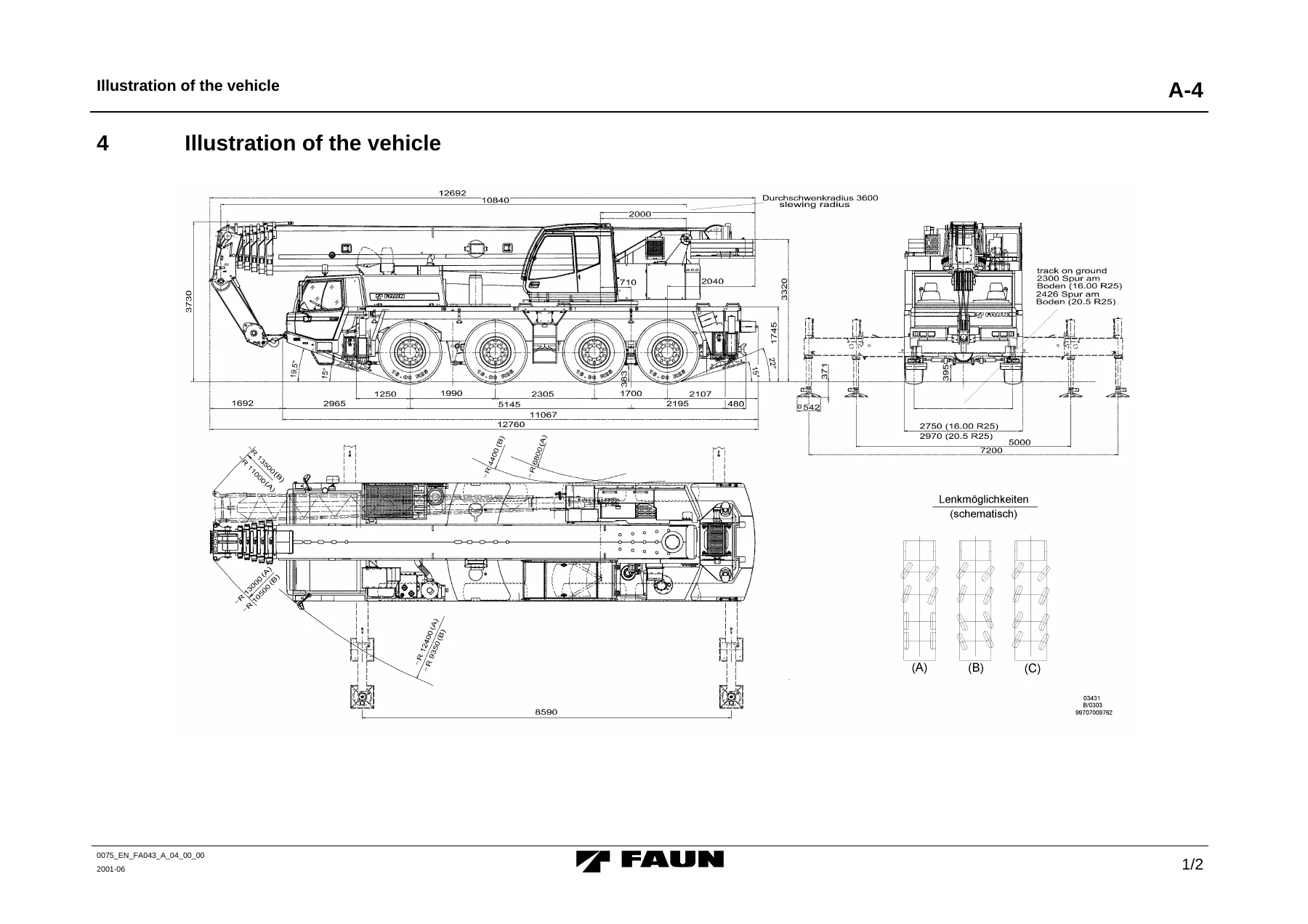
- Part A – General technical details (chassis), dimensions and weights, driving performance data
- Part A – Technical details of components (chassis): engine, gearbox, transfer box, axles, axle suspension, power transmission, wheels and tires, brakes, steering, electrical equipment, instruments, driver’s cab, heating, frame, outriggers, fuel system, tools and accessories, painting, optional equipment
- Part A – Technical details of components (superstructure): engine, hydraulic system, hoisting gear, telescopic boom, boom elevation, swing drive, superstructure frame, safety equipment, electrical equipment, electronic automatic safe load indicator (ASLI), crane cabin, heating, painting, acceptance inspection, counterweights, optional equipment, noise and vibration data
- Part A – Illustration of the vehicle
- Part A – Notes referring to the load (lifting capacity) and supporting forces charts
- Part B0 – Safety Instructions: public road traffic requirements, tire load ratings and travelling speeds, instructions for the crane operator, applications planning, outrigger support, counterweight, hoist winch and rope reeving, wind velocities, hand signals, work near overhead lines, grounding the crane and load, work near supply lines, two-crane lifts, fire and explosion hazards, compressed air tank regulations
- Part B0 – Instruction sheet for overload safety devices for boom cranes
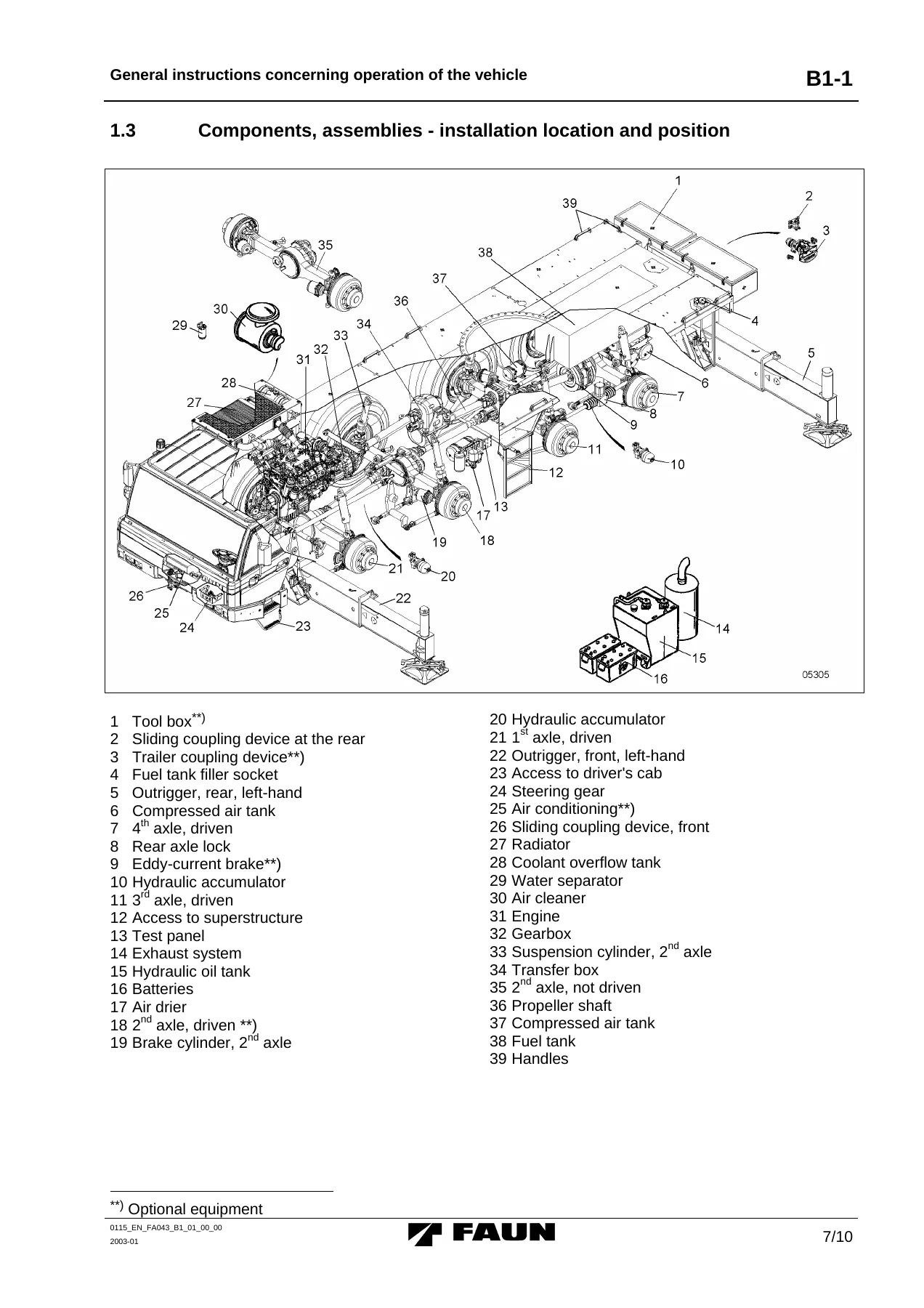
- Part B1 – Chassis Operating Instructions: general operation, warning and instruction plates, components and assemblies, transport condition for public road traffic
- Part B1 – Driver’s cab: control elements, seat adjustment, steering wheel adjustment, roller sun visor, seat belts, cab lighting
- Part B1 – How to put the machine into operation: pre-start checks, electrical equipment, functional checks, air distribution and heating, starting the engine, monitoring indicating and warning lamps
- Part B1 – Gearshift and driving operation: gearbox, transfer box, differential locks and inter-wheel locks, second axle drive, brakes, cruise control, Temposet, steering
- Part B1 – Outrigger the vehicle: locking the axle suspension, electric outrigger actuation, extending and retracting outrigger beams and cylinders
- Part B1 – Emergency control features: emergency control of the hydraulic system
- Part B1 – Operation in winter: engine, gearbox, hydraulic oil, batteries, adjustable air vents, windshield washing system
- Part B1 – Attachments, optional equipment and accessories: electronic immobilizer, fog lights, horns, acoustic reversing signal, centralized lubrication, eddy-current brake, Rockinger and Ringfeder trailer couplings, refrigerator box, tool box, external power source starting, battery charging plugbox, air conditioner, Webasto heaters, emergency OFF switches, spare wheel
- Part B1 – Instrument panel: pilot, indicator and warning lamps, other components, instruments, switches
- Part B2 – Superstructure Operating Instructions: general instructions, warning and instruction plates, components and assemblies
- Part B2 – Crane cabin: control elements, seat adjustment, roller sun visor and skylight, opening the windscreen, rear window, cab lighting, emergency exit, assignment of functions to the crane control levers, superstructure locking system
- Part B2 – How to put the machine into operation: pre-start checks, electrical equipment, functional checks, blower fan, heating, air regulation, starting the engine, monitoring lamps and instruments
- Part B2 – Gearshift and driving operation and actuation of the outriggers from the superstructure
- Part B2 – Crane movements in no-load condition: actuation of the crane control levers, hoisting gear, boom elevation, telescoping, slewing, counterweights, work involving metallic ropes, inspection of the safety equipment
- Part B2 – Crane operation with a load fixed to the boom: outrigger-stabilized operation, free on wheels, driving with a load, moving in full rig arrangement on construction sites
- Part B2 – Emergency operation
- Part B2 – Operation in winter
- Part B2 – Attachments, optional equipment and accessories: double ladder, 9.0/16.0 m boom extension, 2 m boom extension, centralized lubrication, mirror heating, aircraft warning lamp, working floodlights, emergency control of the superstructure via hydraulic motor, supplementary heating, air conditioner, anemometer, front-end pulley, second hoist winch, ASLI shut-off warning, hoist winch service hour monitoring, external starting, battery charging plugbox
- Part B2 – Instrument panel
- Part C1 – Chassis Service and Maintenance: general instructions, welding and straightening, screw coupling inspection, hydraulic leakage checks, cleaning, electronic component configuration
- Part C1 – Maintenance intervals and maintenance schedule (chassis)
- Part C1 – Engine: oil level, oil change and filter replacement, charge air hose clamps, fuel tank, coolant, radiator cleaning, air cleaner, exhaust system
- Part C1 – Gearbox: oil level, oil change and filter replacement, clutch and clutch control mechanism
- Part C1 – Transfer box: oil level, oil change, radiator cleaning
- Part C1 – Axles: oil level and oil change in axle drives and planetary gears, greasing intermediate bearings, greasing axles, leakage and control function checks, axial play and wheel bearing backlash, bolt tightness, preservation, propeller shaft flange screws
- Part C1 – Propeller shafts: backlash, noise test, flange couplings
- Part C1 – Eddy-current brake and breather
- Part C1 – Hydraulic system: oil level, filter cartridge replacement, oil change, oil type change, steering assembly hydraulics, suspension hydraulics, outrigger hydraulics, test connectors and measured values
- Part C1 – Brake system: drainage valves, air drier, pressure governor, brake cylinders, wheel brakes, pressure limiting valve, automatic anti-block system (ABV), engine brake, test connectors, setting values
- Part C1 – Electrical equipment: batteries, three-phase generator, starter, lamps and lights, fuse and relay arrangement
- Part C1 – Wheels and tires: accident prevention, wheel nut tightness, tightening torque, tire pressure, disc wheel replacement, wheel interchange
- Part C1 – Outriggers: guide pad adjustment, cable drag chain check
- Part C1 – Driver’s cab: warm water heating, wiper blades, air conditioner, supplementary heater, engine pre-heating
- Part C1 – Miscellaneous: other lubrication points, filter replacement in the supplementary heater fuel pipe, trailer coupling devices, sliding coupling, steering, suspension, centralized lubrication
- Part C1 – Summary of oil types and filling capacities, lubricating grease types, approved consumables, inspection/cleaning/oil level/lubrication schemes
- Part C2 – Superstructure Service and Maintenance: maintenance intervals and maintenance schedule (superstructure)
- Part C2 – Engine, hydraulic system, swing mechanism, hoisting gear and auxiliary hoisting gear, winch rope, electrical equipment, crane cabin, other points of lubrication, servicing and maintenance
- Part C2 – Summaries, schemes and charts
- Part D – Circuit and piping diagrams: chassis electric circuits, pneumatic diagrams, hydraulic piping diagrams; superstructure electric circuits, hydraulic diagrams
- Part E – Crane testing instructions: supporting steel structures, hook blocks, lifting ropes, working life of the rope winch gear assemblies, monitoring the slewing device
- Part F – Troubleshooting: chassis and superstructure
- Part G – Annex: ZF gearbox operating instructions and chart of lubricants, PAT DS 350 load moment limiter manual, centralized lubrication system, heating, ventilation and air conditioning documents
Read as a whole, the Tadano Faun ATF 80-4 Operating, Service and Maintenance Manual ties the carrier and the superstructure together in one reference. The operating sections explain how both halves of the machine are put into service and driven, the service sections define what has to be greased, drained, checked and adjusted at every interval from daily to 2000 operating hours, and the diagrams and troubleshooting sections provide the wiring, hydraulic and fault-finding back-up when something goes wrong. Load charts, supporting force charts, rope reeving diagrams and counterweight assembly sequences are included so that lifting work is planned against the crane’s real capacities rather than estimates. The annex collects the ZF gearbox documentation and the PAT DS 350 automatic safe load indicator operating manual, which together remove the need for separate OEM brochures during routine workshop work.
What This Manual Enables You To Do
- Operate both the carrier and the superstructure safely, including outrigger setup, counterweight handling, rope reeving and free-on-wheels lifts
- Carry out scheduled maintenance on the Mercedes-Benz OM 501 LA carrier engine and the Mercedes-Benz OM 904 LA superstructure engine
- Service the ZF AS-Tronic 12AS2302 gearbox, transfer box, axles, brakes and hydraulic system to the specified intervals and capacities
- Diagnose faults in the chassis and superstructure using the dedicated troubleshooting tables
- Read and apply the load charts, supporting force charts and ASLI codes for the correct rig arrangement
- Follow the crane testing instructions for supporting structures, hook blocks and lifting ropes
Why Correct Procedures and Specs Matter
Mobile crane work leaves no margin for approximate torque values, incorrect tire pressures or guessed maintenance intervals. The ATF 80-4 carries high-tensile fine grain steel structures, hydro-pneumatic suspension, an air-operated dual-circuit brake system and a six-section telescopic boom, and each of those systems has a defined service routine with measurable values. This manual records those values so the machine can be kept within the limits the manufacturer intended, from the pre-start inspection through to the rope discard criteria and the slewing device wear check.
IMAGES PREVIEW
Instant PDF Delivery
The Tadano Faun ATF 80-4 Operating, Service and Maintenance Manual is delivered as an instant PDF download after payment. There is no shipping and no waiting for a printed copy. The file opens on any laptop, tablet or phone, and pages can be printed for the cab or the workshop when a paper copy is more practical on site.



Reviews
There are no reviews yet.