
Taylor-Dunn Electrical Troubleshooting Manual M7-001-69 – Curtis PMC AC Sevcon DC Charger Diagnostic Guide
Original price was: $34.95.$21.95Current price is: $21.95.
265-page Taylor-Dunn electrical troubleshooting manual M7-001-69 covering Curtis PMC, Curtis AC, Sevcon DC, Sevcon AC, and Power-Tron 240/350 motor speed control systems plus Lester, Signet, Delta-Q, and Summit battery chargers with diagnostic trouble codes, component testing, and system identification procedures.
Description
Taylor-Dunn Electrical Troubleshooting Manual M7-001-69
The Taylor-Dunn Electrical Troubleshooting Manual M7-001-69 is the definitive diagnostic resource for technicians working on Taylor-Dunn electric vehicles. This 265-page manual provides structured troubleshooting procedures for every major motor speed control system and battery charger used across the Taylor-Dunn vehicle line. Whether you are diagnosing a fault code on a Curtis PMC controller, testing a Sevcon Gen4 AC system, or tracing a charging issue through a Lester Summit charger, this manual delivers the test sequences, voltage specifications, and component-level procedures needed to isolate the problem.
Published by Taylor-Dunn Manufacturing and revised through May 2020, this manual is written for qualified electrical technicians familiar with digital multimeters, test lights, and electronic diagnostic tools. It covers vehicles equipped with Curtis PMC, Curtis PMC-EEC, Curtis AC, Sevcon PowerPak, Sevcon MicroPak, Sevcon AC, Sevcon Gen4 AC, Power-Tron 240, Power-Tron 350, and Power-Tron II control systems.
File Details
- Manual Type: Electrical Troubleshooting Manual
- Brand: Taylor-Dunn
- Document Number: M7-001-69
- Publication Date: Originally Published August 20, 2012; Revision V, May 20, 2020
- Language: English
- Page Count: 265 pages
- File Format: PDF
- Publisher: Taylor-Dunn Manufacturing, 2114 West Ball Road, Anaheim, CA 92804
Chapters Covered
- Introduction — About this manual, Who Should Read This Manual, Replacement Parts, Web Site Registration, Conventions, Signal Words and Their Definitions, Glossary, Vehicle Modifications, Using Non-OEM Replacement Components, Motor Speed Control Programming
- READ ME FIRST, Instructions — Safety warnings, test preparation, vehicle support requirements
- Motor Speed Control System Identification — Curtis PMC (Taylor-Dunn), Curtis PMC-EEC, Curtis AC, Sevcon PowerPak, Sevcon MicroPak, Sevcon AC, Power-Tron 240, Power-Tron 350, Power-Tron II
- Charger Identification — Lester Lestronic II, Lester X-Series, Lester Summit, Lester Summit II, Signet model HB, Signet model HBS, Delta-Q QuiQ, Delta-Q IC650
- Component Identification — Directional Solenoid (F&R), Isolator Solenoid (ISO), Circuit Breaker (Main and 10/20 Amp), Throttle Module T/D, Throttle Module Sevcon, Direction Control Switch, Motor Windings (Armature and Field), Series Wound Motors, SEPEX/SEM Motors, AC Motors
- Tools Available from Taylor-Dunn — Throttle Module Analyzer, Throttle Module Test Harness, Test Light, Sevcon DC System Handsets, Curtis AC System Handset, Sevcon Gen4 Handset, Hydrometer, Pin Removing Tools
- PMC Control System (std) — Electrical Test Equipment Required, Instructions, Symptoms, Quick Test, Complete System Diagnosis, Test Procedure 1 through 8, Symptom Troubleshooting, Motor, Solenoids, Motor Control, Plugging Diode, ISO, Freewheel Diode, HPD
- PMC Control System (EEC) — Electrical Test Equipment Required, Instructions, Definitions, Symptoms, Preliminary System Tests, Controller Battery Supply, Controller Output, Controller Small Signal Input, Forward/Reverse Switch (Model ET-150-74 and 48 Volt System), Motor, Contactors, ISO Contactor, Contactor Negative Return, Symptom Troubleshooting
- Curtis AC Control System — Electrical Test Equipment Required, Instructions, Handset Connection, Control Voltage Inputs, System Fault Codes (DTCs), Using the Handset, Adjustable Parameters, Taylor-Dunn Parameter Table, Monitor Menu
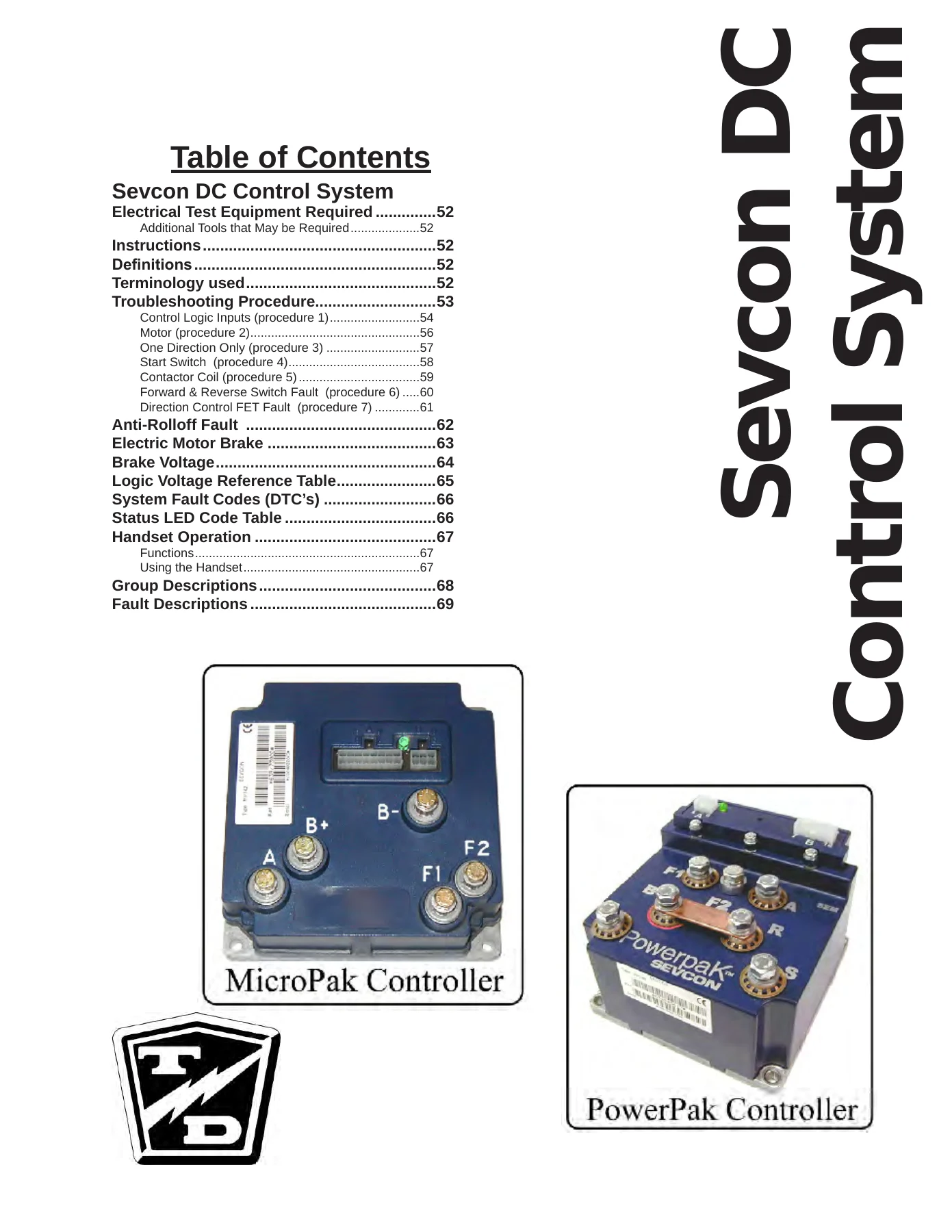
- Sevcon DC Control System — Electrical Test Equipment Required, Instructions, Definitions, Terminology, Troubleshooting Procedure, Control Logic Inputs, Motor, One Direction Only, Start Switch, Contactor Coil, Forward & Reverse Switch Fault, Direction Control FET Fault, Anti-Rolloff Fault, Electric Motor Brake, Brake Voltage, Logic Voltage Reference Table, System Fault Codes, Status LED Code Table, Handset Operation, Group Descriptions, Fault Descriptions
- Sevcon AC Control System — Theory of Operation, Diagnostic Information, Electrical Test Equipment Required, Faults, Vehicle Status Screen, Vehicle Inputs Monitor, Definitions, Handset Connection
- Power-Tron 240/350 Control System — Electrical Test Equipment Required, Instructions, Diagnosis Procedure, Solenoids, ISO, Forward Only, Forward Contacts, Reverse Only, Reverse Contacts
- Diagnostic Trouble Codes — Sevcon PowerPak and MicroPak (F01004 through F05046), Curtis PMC AC (DTC 12 through DTC 77), Sevcon Gen4 AC (F16010 through F53008)
- Lestronic II Charger — Test Equipment Required, Instructions, Theory of Operation, Built-in Charger, Portable Charger Troubleshooting
- Lester X-Series Charger — Electrical Test Equipment Required, Instructions, Theory of Operation, Fault and Diagnostic Error Code Table, Fault Code Chart, Internal Wiring Diagram, Self Diagnostics, Testing the Charging Cycle, SCR Assembly, Transformer, Lock Out Relay, Relay Board Assembly, Control Board Assembly, Profile Setting
- Signet HBS Charger — Electrical Test Equipment Required, Instructions, Definitions, Operating Instructions and Theory of Operation, Testing the Charging Cycle, Status Light Error Code Table, Troubleshooting
- Signet HB Charger — Electrical Test Equipment Required, Instructions, Operating Instructions and Theory of Operation, Charging Status Lights, HB/PT and GEL Indicator Lamps, Testing the Charging Cycle, Status LED Error Code Table, Troubleshooting
- Delta-Q ‘QuiQ’ Charger — Electrical Test Equipment Required, Instructions, Theory of Operation, Fault and Diagnostic Error Codes, Troubleshooting, Charging Profiles, Confirming Active Profile, Changing the Profile
- Delta-Q IC650 Charger — Electrical Test Equipment Required, Instructions, Theory of Operation, Fault Code Table, Changing the Charging Profile
- Lester Summit Charger — Electrical Test Equipment Required, Instructions, Theory of Operation, Diagnostic Fault Codes
- Component Testing — Electrical Test Equipment Required, Instructions, Throttle Module T/D (Handset and Test Harness), Throttle Module FS-1 Fault (Curtis DC, Curtis AC, Sevcon AC, Sevcon DC), Throttle Switch Rheostat, Solid State Relay, 12v DC-DC Converter, Low Speed Module, Contactors (Solenoids), AC Motor Specs (DLGF 112150-4, 191624805/191624806, VCM1714416DAD-E0, ACX-3266, IM150229, 191668501), AC Motor Thermal Sensor Graph, DC Motors (Separately Excited Fields, Series Wound Fields, Exploded Armature, Burnt Commutator, Burnt Brush Lead), Charger Interlock Relay, Speed Sensor Magnetic
This manual is organized around the diagnostic workflow: identify the control system installed on the vehicle, perform the preliminary voltage checks, follow the test procedures in sequence, and use the symptom-based troubleshooting tables when the fault matches a specific pattern. Every control system chapter includes a complete system diagnosis sequence that walks through power output tests, control wire inputs, power wire inputs, motor testing, start switch verification, direction control switch testing, and solenoid/contactor checks. The diagnostic trouble code chapters provide code-specific causes, troubleshooting steps, and clearing procedures for Sevcon PowerPak/MicroPak, Curtis PMC AC, and Sevcon Gen4 AC systems.
Diagnostic Trouble Code Coverage
The DTC sections are among the most practical parts of this manual. Each code entry includes the circuit function, known causes, troubleshooting steps, and how to clear the code. For Sevcon PowerPak and MicroPak systems, codes like F01004 (Low Battery Volts), F02000 (Accelerator), F04003 (MOSFET Short Circuit), and F05000 (VA Fail) are documented with wiring diagrams. Curtis PMC AC DTCs from 12 (Controller Overcurrent) through 77 (Supervisor Fault) include detailed circuit function descriptions. Sevcon Gen4 AC fault codes are cross-referenced by display code and controller fault ID, covering battery faults, motor faults, encoder faults, contactor faults, and MOSFET short circuits.
Charger Systems Covered
Charger troubleshooting covers the full range of Taylor-Dunn battery charging systems. The Lestronic II chapter explains the semi-automatic charging theory and provides separate procedures for built-in and portable configurations, including transformer, capacitor, diode, and timer board testing. The Lester X-Series chapter includes a full fault code chart, self-diagnostics procedure, charging cycle testing, SCR assembly testing, lockout relay testing, relay board assembly checks, and profile setting for WET/FLA versus SLA/AGM batteries. Signet HB and HBS chargers are covered with their LED status codes and charging cycle test procedures. Delta-Q QuiQ and IC650 chargers include charging profile confirmation and change procedures, plus complete fault code tables. The Lester Summit charger chapter provides diagnostic fault codes based on the three status LEDs.
Component Testing
The component testing chapter provides bench and in-vehicle test procedures for individual components. Throttle module testing covers both the Taylor-Dunn module using the analyzer or test harness, and the FS-1 fault diagnosis for Curtis DC, Curtis AC, Sevcon AC, and Sevcon DC systems. The rheostat throttle switch, solid state relay, 12v DC-DC converter, and low speed module each have dedicated test procedures. Contactor testing includes specifications for coil voltage, coil resistance, actuation current, and pick-up voltage for SPST (ISO) and SPDT (F&R) contactors. AC motor specifications are provided for DLGF 112150-4, 191624805, 191624806, VCM1714416DAD-E0, ACX-3266, IM150229, and 191668501, including phase winding resistance, thermal sensor resistance versus temperature, and encoder testing. DC motor sections cover separately excited and series wound field motors with armature and field resistance specifications. The charger interlock relay and magnetic speed sensor round out the component coverage.
What This Manual Enables
With the Taylor-Dunn Electrical Troubleshooting Manual M7-001-69, a technician can systematically diagnose electrical faults across the entire vehicle control system. The manual supports:
- Identifying which motor speed control system and charger are installed on a given vehicle
- Performing preliminary voltage and continuity checks at the controller, solenoids, and motor
- Following complete system diagnosis procedures for PMC, PMC-EEC, Curtis AC, Sevcon DC, Sevcon AC, and Power-Tron systems
- Interpreting diagnostic trouble codes from controller status LEDs and handsets
- Testing and evaluating throttle modules, contactors, motors, encoders, and thermal sensors
- Diagnosing charger faults using fault code tables, self-diagnostics, and component-level tests
- Confirming whether a component has failed before replacing it
- Verifying that the control system is functioning correctly after a repair
The manual emphasizes proper test sequence, warns against skipping steps, and includes safety requirements such as supporting the drive wheels off the ground during testing and discharging controller capacitors before working on power terminals. Voltage reference tables, logic input tables, and symptom-to-procedure cross-reference charts help narrow down faults quickly.
Why This Manual Matters
Electrical faults in electric vehicles can be difficult to isolate without the correct test procedures and voltage specifications. Replacing parts by guesswork is expensive and may not address the root cause. This manual provides the manufacturer’s test sequences, expected voltage readings, resistance values, and fault code definitions needed to diagnose problems correctly the first time. It covers the interaction between the motor controller, throttle, direction control, contactors, motor, and charger, so the technician can understand how a fault in one area produces symptoms in another.
Note: This manual is for testing and diagnosis only. It does not include repair procedures. Refer to the vehicle service manual for repair information.
Delivery
IMAGES PREVIEW
This Taylor-Dunn Electrical Troubleshooting Manual M7-001-69 is delivered as an instant PDF download after payment. No shipping, no waiting for a physical book. The file can be viewed on any device — laptop, tablet, or smartphone — and printed if a paper copy is preferred for the shop. With 265 pages of diagnostic procedures, fault code tables, wiring diagrams, and component specifications, this manual is a practical reference for any technician servicing Taylor-Dunn electric vehicles.
Reviews
There are no reviews yet.