
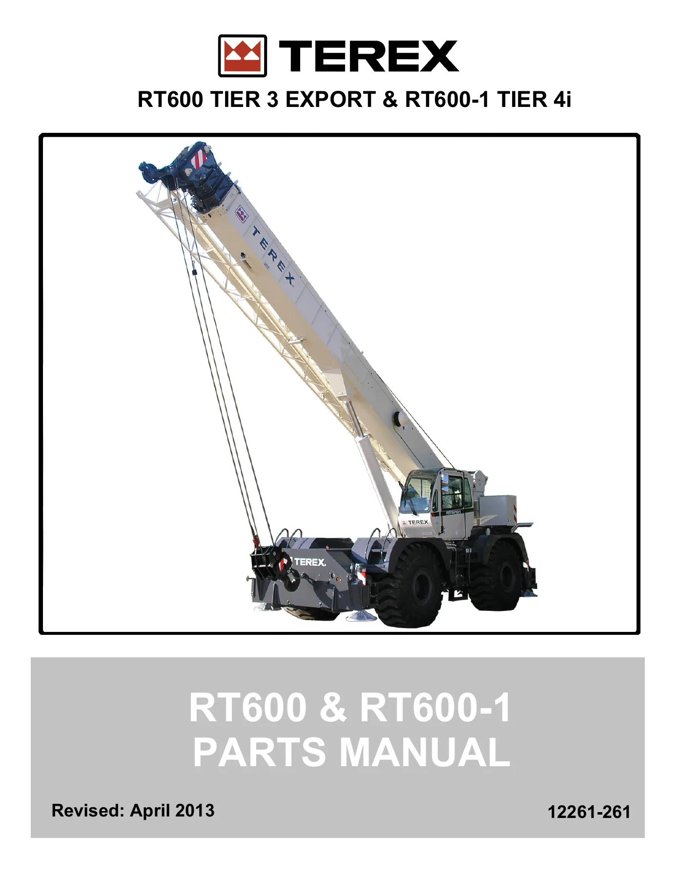
Terex RT600 and RT600-1 Rough Terrain Crane Parts Manual 12261-261
Original price was: $39.95.$24.95Current price is: $24.95.
Complete parts manual for Terex RT600 and RT600-1 Rough Terrain Cranes (Part No. 12261-261, Revised April 2013). Features fully illustrated exploded parts diagrams, component breakdowns, and exact part numbers across Cummins QSB6.7 engines, Dana 32000 transmission, AxleTech and ArvinMeritor axles, full hydraulics, 111-foot boom, winch assemblies, and cab.
Description
Terex RT600 and RT600-1 Rough Terrain Crane Parts Manual 12261-261
The Terex RT600 and RT600-1 Rough Terrain Crane Parts Manual 12261-261 provides an exhaustive, factory-level catalog of every serviceable assembly, subassembly, and individual component for the RT600 Tier 3 Export and RT600-1 Tier 4i rough terrain cranes. Revised in April 2013 under Terex Cranes publication number 12261-261, this publication serves as the authoritative parts reference for crane owners, fleet managers, field mechanics, and parts procurement specialists. Whether maintaining a Tier 3 Cummins export unit or a Tier 4i crane equipped with advanced exhaust aftertreatment, this manual delivers complete exploded illustrations, exact part numbers, quantities required per assembly, and clear structural relationships to keep your rough terrain crane operating at peak jobsite reliability.
Manual File Details
- Manual Type: Parts Manual / Illustrated Parts Catalog
- Brand: Terex Cranes
- Equipment Covered: Terex RT600 & RT600-1 Rough Terrain Cranes (Tier 3 Export, Tier 4i, and Non-North America)
- Document / Part Number: 12261-261
- Publication Revision: Revised April 2013
- Total Page Count: 370 Pages
- Language: English (includes marking decals in Spanish, Portuguese, French, and Russian)
- File Format: Adobe Digital PDF
Chapters and Parts Groups Covered
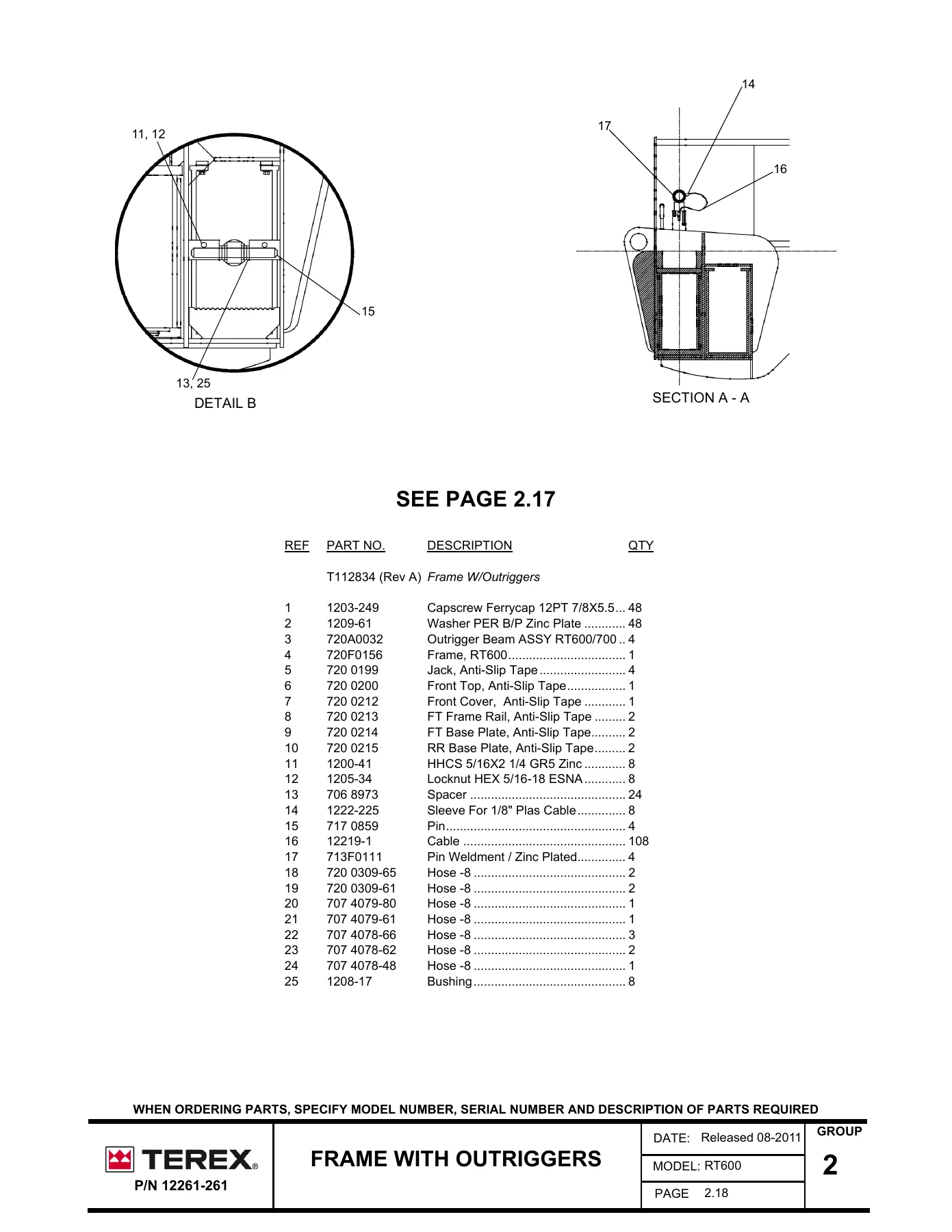
- Group 2 — Carrier Frame & Fuel Tank: Fender & Deck Assembly, Carrier Frame Weldments, Machining Details, Hydraulic Reservoir Tank Assemblies, 80-Gallon Fuel Tank Assemblies, Axle Lock-Out Assembly, Axle Lock-Out Cylinders, Pintle Hook Assemblies, and Frame with Outrigger Box Structures.
- Group 3 — Outriggers: Outrigger Beam Assemblies, Jack Cylinders, Extension Cylinders, Outrigger Control Valve Hydraulics, Extension/Retraction Valves, Hydraulic Selector Valves, Aluminum Outrigger Pads, Outrigger Proximity Sensor Installation, and Sensor Mount Assemblies.
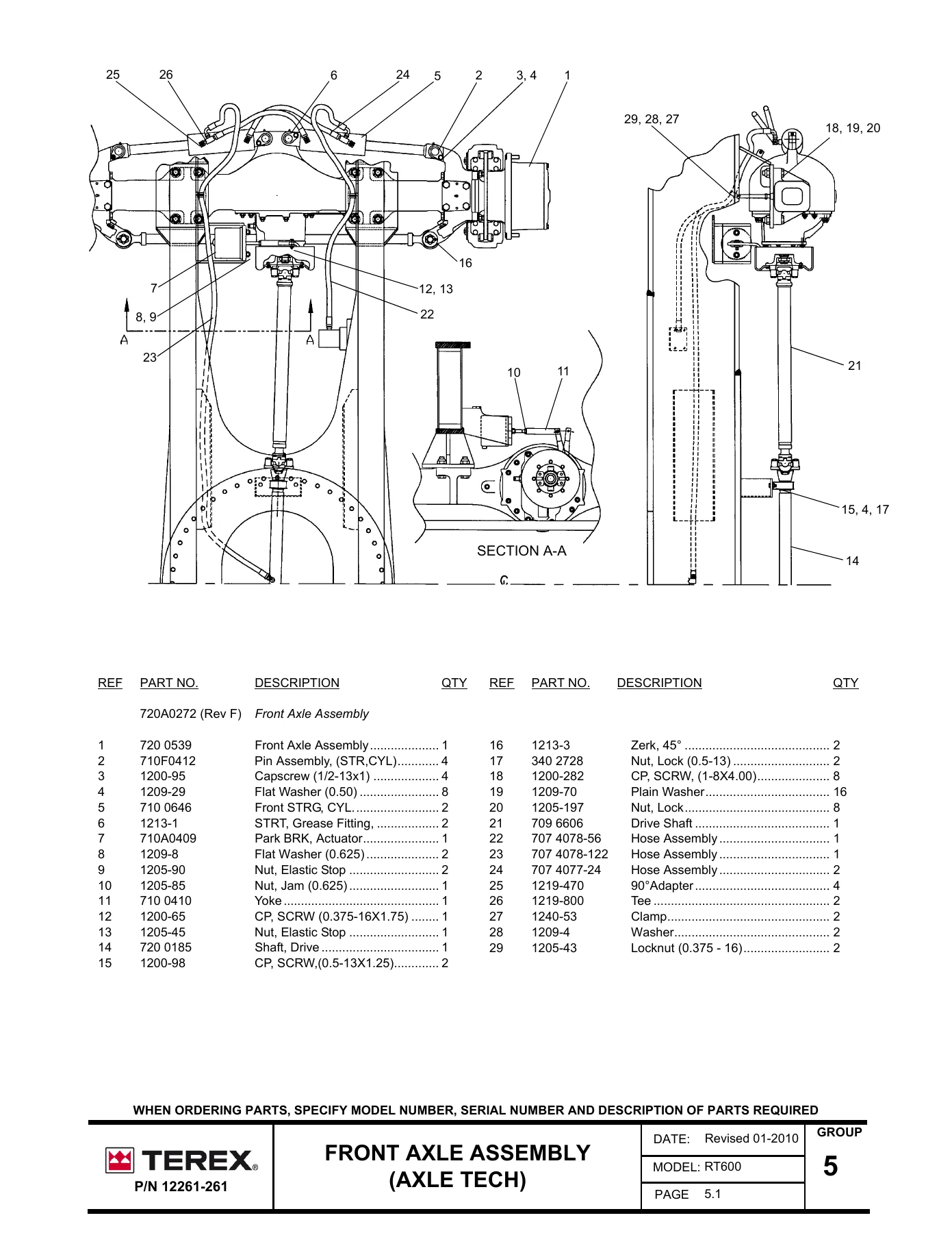
- Group 5 — Carrier Axles (AxleTech): Front Axle Assemblies, Planetary Front Axles, Axle Housing Groups, Front & Rear Disc Brake Assemblies, Differential Carrier Assemblies, Hub & Shaft Groups, Steering Knuckles, Tie Rod Assemblies, Rear Axle Assemblies, and Rear Planetary Groups.
- Group 5A — Carrier Axles (Welded Meritor Axle): Front Axle Assemblies with Welded Housing, ArvinMeritor Front Axle Components, Planetary Wheel End Assemblies, Rear Axle Assemblies with Welded Housing, and ArvinMeritor Rear Axle Components.
- Group 5B — Carrier Axles (Cast Meritor Axle) & Wheels: Front Axle Assemblies with Cast Housing (Beginning with SN # 161240), ArvinMeritor Cast Axle Internals, Planetary Wheel End Groups, Rear Axle Assemblies with Cast Housing, and 29.50×25 Heavy-Duty Wheels and Tires.
- Group 6 — Carrier Engine (Export Tier 3): Cummins QSB6.7 215 HP Tier 3 Engine Installation, Air Intake Piping, Exhaust Piping and Muffler, Engine Mounts, and Shift Valve Assembly.
- Group 6A — Carrier Engine (Tier 4i): Cummins QSB6.7 220 HP Tier 4i Engine Installation, Diesel Particulate Filter (DPF) Subassembly, Flexible Exhaust Piping, Cooling Package, Radiator and Charge Air Cooler Mounts, and Hydraulic Pump Drive Mounting.
- Group 6B — Carrier Engine (Non-North America Tier 3): Cummins QSB6.7 220 HP Tier 3 Engine Installation for Rest of World (ROW), Spark Arrestor Muffler and Exhaust Assembly, Air Cleaner Mounting, and Fuel Lines.
- Group 7 — Transmission: Dana 32000 Series Powershift Transmission, Torque Converter Groups (Aluminum and Steel Converter Designs), Converter & Transmission Case Group, Reverse, 3rd, Forward & 2nd Clutch Groups, Low 1st Clutch & Output Shaft Group, Transmission Charging Pump, Pressure Regulating Valve & Filter Assembly, Electric Control Valve Assembly, High/Low Shift Control Assembly, Pump Disconnect Mechanism, and Drive Plate Group.
- Group 9 — Drive Shafts: Front and Rear Drive Shaft Assemblies, Universal Joint Spider and Bearing Kits, Slip Yokes, and Center Support Bearings.
- Group 10 — Brakes: Service Brake Line Piping, Relay Valves, Air Reservoirs, Hydraulic Pressure Converters, Stop Light Switches, Dual Pressure Air Supply Systems, Air Dryers, and Operator Cab Air Brake Kit.
- Group 11 — Steering: Orbitrol Steering Control Unit, Steering Column Assembly, Front and Rear Steering Cylinders, Steering Mode Selector Valve Hydraulics, and Hydraulic Steering Control Valves.
- Group 12 — Superstructure: Upper Superstructure Frame Weldment, Heavy-Duty Swing Bearing Assembly, Cab Mounting Brackets, and Vibration Isolators.
- Group 13 — Counterweight: 13,100 lb Counterweight Assembly (with Auxiliary Winch configuration) and 14,200 lb Counterweight Assembly (without Auxiliary Winch configuration).
- Group 22 — Swing System: Braden Swing Drive Unit, Planetary Swing Reduction Gearbox, Eaton Hydraulic Swing Motor, and Swing Brake Assembly.
- Group 24 — Pump Drive Case & Hydraulic Pumps: Triple and Tandem Hydraulic Gear Pumps, Winch Drive Pumps, and Boom/Telescope/Swing Hydraulic Supply Pumps.
- Group 25 — Hydraulic System: Lower Chassis Hydraulics, Swivel Joint / Center Rotary Manifold, Outrigger Solenoid Valves, Diverter Valves, Upper Superstructure Hydraulics, Winch Control Valves, Telescoping Boom Control Valves, Steering Priority Valve, Counterbalance Hold Valves, and Hydraulic Oil Reservoirs.
- Group 27 — Operator’s Cab & Machinery Housing: Cab Shell Weldment, Windshield and Roof Hatch Glazing, Wiper Mechanisms, Adjustable Operator Seat, Engine Cowling, and Cab Floor Pedals.
- Group 28 — Operator’s Controls: Multi-Axis Hydraulic Joystick Modules, Single-Axis and Dual-Axis Armrest Controllers, Transmission Gear Shifter, Directional Signal Control, Swing Brake Pedal, Swing Lock Controls, and Foot Throttle Control.
- Group 30 through 30D — Markings & Decals: Complete Tier 3 and Tier 4i Crane Decal Kits, Warning Labels, and Multi-Language Markings in Spanish, Portuguese, French, and Russian.
- Group 31 — Cab Heater & Air Conditioning: Hydraulic Air Conditioning Systems, LP Gas Heaters, Suburban Heaters, and Deluxe Flameless Cab Climate Systems.
- Group 33 — Electrical System: Cab Dash Assemblies, Instrument Clusters, Wiring Harness Routing, Relay Panels, Circuit Breakers, 12V Battery Configurations, and Strobe/Work Light Packages.
- Group 39 & 39A — Telescoping Boom & Jibs: 111-Foot Four-Section Telescopic Boom, Boom Extension Cylinder, Boom Hoist Cylinder, Boom Head Sheave Assemblies, 32-Foot Fixed Jib, and 33-Foot to 57-Foot Offsettable Lattice Jib Assemblies with Stowage Brackets.
- Group 40, 44 & 45 — Winches, Hook Blocks & Wire Rope: Main and Auxiliary Hydraulic Winches, Rexroth and VOAC Piston Winch Motors, Tension Rollers, 60-Ton 5-Sheave Hook Block, Heavy-Duty Overhaul Ball, and Hoist Wire Rope Reeving Arrangements.
- Group 50 & 52 — Attachment Options & RCI: Auxiliary Winch Assemblies, Auxiliary Boom Nose Sheave, Greer RCI 510 Rated Capacity Indicator Computer, Cable Extension Reels, and Anti-Two Block Sensors.
- Group 54, 55 & 56 — Filters, Spare Parts & Options: Preventive Maintenance Filter Kits (Tier 3 and Tier 4i), Recommended Stocking Spare Parts Lists, 3rd Wrap Winch Drum Indicators, and Emergency Engine Shutdown Kits.
This comprehensive directory provides technicians, parts inventory specialists, and crane mechanics with direct access to every factory assembly group. Rather than relying on guesswork when matching hydraulic hoses, structural pins, clutch friction discs, or electronic sensors, this manual provides exact Terex part numbers and physical component layouts to verify every installation.
Chassis, Carrier Frame, and Outrigger Subsystems
The chassis foundation of the Terex RT600 and Terex RT600-1 crane utilizes an integrated box frame designed to withstand high torsional and bending stresses during heavy lifting and rough terrain transit. Group 2 and Group 3 of the parts catalog document the primary structural weldments, including front and rear outrigger box structures, frame machining details, deck plating, access ladders, and fender assemblies. Hydraulic fluid and fuel storage systems are fully detailed, featuring complete breakdowns of the 80-gallon fuel tank with sending units, adapters, and mounting hardware, alongside hydraulic reservoirs equipped with internal suction strainers, return filters, sight level gauges, and pressure bypass valves.
Outrigger assemblies feature high-strength extend beams, double-acting hydraulic jack cylinders (Part No. 717 0001), and internal extend cylinders (Part No. 720 0043). The manual illustrates the internal seal rebuild kits, cylinder barrels, chrome-plated rods, piston heads, and integrated Sun dual counterbalance check valves. In addition, the catalog provides complete coverage of chassis outrigger hydraulics, including solenoid control valves, hydraulic diverter manifolds, Parker selector valves, removable aluminum outrigger float pads, and proximity sensor mounting brackets used with outrigger position monitoring systems.
Axle Tech and ArvinMeritor Axle Configurations
Crane drivelines experience extreme loads, and this manual provides complete, dedicated parts coverage across three distinct axle designs fitted to the RT600 and RT600-1 series:
- AxleTech Planetary Drive-Steer Axles: Detailed in Group 5, including front axle assembly (720 0539) and rear axle assembly (720 0540). Exploded views detail the central axle housing, magnetic drain plugs, spindle bushings, heavy-duty kingpins, steering knuckles, disc brake calipers with four-piston finish, carrier differential assemblies with limited-slip differentials, planetary ring gears, sun gears, thrust washers, and tie rod assemblies.
- ArvinMeritor Welded Housing Axles: Fully broken down in Group 5A, featuring welded axle housings (T105751 front, T105753 rear), kingpin caps, grease fittings, spiral pins, universal joint shaft assemblies, internal planetary wheel ends, metal face oil seals, tapered roller bearings, and disc brake caliper mounting brackets.
- ArvinMeritor Cast Housing Axles: Documented in Group 5B for cranes beginning with serial number 161240. This section specifies cast housing components (T128553 front, T128556 rear), upgraded tie rod end assemblies, wheel hubs, planetary carrier spiders, pinion gear needle bearings, and 46-stud wheel hub assemblies matching heavy-duty 29.50×25 earthmover tire fitments.
Complete driveline connections are documented in Group 9, including heavy-duty front and rear drive shafts, universal joint cross and bearing repair kits, slip yokes, dust caps, and center bearing supports.
Cummins Tier 3 Export, Tier 4i, and Global Engine Packages
Because engine specifications vary by manufacturing year, emissions standard, and geographic delivery, this parts manual provides segregated, detailed groups for each power plant installed on the RT600 and RT600-1 crane platforms:
- Export Tier 3 Cummins QSB6.7 (215 HP): Group 6 breaks down engine package T118709, illustrating charge air connections, intake manifolding, Donaldson heavy-duty air cleaners, flexible exhaust downpipes, commercial mufflers, rain caps, rubber vibration isolator mounts, and the chassis shift valve assembly.
- Tier 4i Cummins QSB6.7 (220 HP): Group 6A details engine installation T109820 and engine subassembly T103328. This comprehensive section covers the Diesel Particulate Filter (DPF) subassembly, V-band exhaust clamps, hot and cold charge air cooler (CAC) aluminum piping, heavy-duty cooling package with modular fan shroud, transmission oil cooler, hydraulic cooler, radiator, and dedicated fuel filter water separator mounts.
- Non-North America Tier 3 Cummins QSB6.7 (220 HP): Group 6B covers the Rest of World (ROW) engine package (T117307 / T103329), documenting specialized air intake routing, flexible exhaust joints, and spark-arresting mufflers with integrated heat shields for refinery and industrial site compliance.
Dana 32000 Series Powershift Transmission
Group 7 of the parts catalog covers the Dana 32000 Series powershift transmission (Part No. 710 0321), delivering component-level breakdowns across every mechanical, hydraulic, and electronic subsystem. Illustrated pages document both aluminum and steel torque converter impeller and turbine configurations, reaction members, stator supports, and input charging pumps. The transmission casing group details oil suction tubes, internal lube manifolds, magnetic drain plugs, and speed sensor shims.
The manual provides complete clutch pack exploded views, showing inner friction discs, outer steel separator plates, piston return disc springs, Belleville springs, lip seals, and piston metering seals for the Reverse, 3rd, Forward, 2nd, and Low 1st speed gear sets. Supporting controls include the main transmission charging pump with integrated pressure regulating relief valve, filter adapter assemblies, the multi-spool electric shift control valve with 12V solenoid cartridges, the air-actuated High/Low range shift cylinder, and the hydraulic pump disconnect mechanism allowing pump disengagement during highway travel.
Hydraulic Systems, Rotary Swivel, and Superstructure Winches
The hydraulic system of the Terex crane is mapped out with engineering precision across Group 24 and Group 25. Group 24 documents the primary hydraulic pump configuration, detailing multi-section gear pumps powering main winch, auxiliary hoist, boom telescope, and superstructure swing functions. Group 25 covers all chassis and superstructure hydraulic plumbing, beginning with the heavy-duty central hydraulic swivel (Part No. 720 0107) and electrical slip ring assemblies (Part No. 723A0106 and T120717) that transfer fluid and electrical signals continuously across the 360-degree rotating turret.
Superstructure control valves include the proportional boom hoist and telescope valve, the main winch control valve, the Eaton swing valve, and steering priority flow divider valves. Hoist mechanics are supported by detailed breakdowns of the main hoist winch (Part No. 720 0408), Rexroth 9-piston and VOAC bent-axis hydraulic winch motors, internal multi-disc wet brakes, cable tension rollers, and wire rope spooling guides. Superstructure rotation is detailed through the Braden swing reduction gearbox (Part No. 710 0304), showing internal planetary carriers, sun gears, output pinion shafts, and mechanical swing lock assemblies.
Four-Section Telescopic Boom, Jibs, and Operator Cab
Boom and lifting hardware are detailed in Group 39 and Group 39A. The 111-foot four-section full-power telescoping boom includes structural boom sections, internal boom extend hydraulic cylinders, counterbalance holding valves, wear pads with adjustment shims, wire rope sheaves, and the 5-sheave boom head assembly. Jib equipment includes 32-foot fixed lattice swing-on jibs and 33-foot to 57-foot offsettable telescopic jibs with stowage pins and anti-two-block sensor switches.
Operator station coverage in Group 27, Group 28, and Group 33 details the cab shell, safety glass windshield, overhead skylight, wiper assemblies, sliding cab door, suspension operator seat, and multi-axis electro-hydraulic pilot joysticks. Safety monitoring is reinforced with complete schematics and part numbers for the Greer RCI 510 Rated Capacity Indicator computer console, extension reel potentiometers, boom angle sensors, and load cells.
Parts Identification and Accurate Ordering Guide
Using the Terex RT600 and RT600-1 Rough Terrain Crane Parts Manual 12261-261 ensures accurate part identification and prevents costly ordering errors. Every illustrated plate features exploded line art keyed with numbered reference balloons corresponding directly to the tabulated parts list on the opposite page. Each line entry specifies:
- Reference Number: Keyed to the exploded drawing balloon.
- Terex Part Number: The exact part number to quote to your Terex Cranes distributor or parts supplier.
- Component Description: Exact engineering nomenclature, including thread sizes, dimensions, and material specifications.
- Quantity Required: Total quantity of that specific part utilized per assembly or subassembly.
- Model Applicability & Serial Breakpoints: Specific callouts distinguishing between RT600, RT600-1, Tier 3, Tier 4i, or serial number changes such as Meritor cast axle updates beginning at SN 161240.
Maintain Jobsite Uptime with Complete Factory Parts Data
Maintaining a heavy rough terrain crane requires absolute precision in component replacement. The Terex RT600 and RT600-1 Rough Terrain Crane Parts Manual 12261-261 empowers maintenance superintendents, field technicians, and crane repair shops to independently inspect, source, and rebuild complex crane assemblies. By referencing exact exploded diagrams and OEM part numbers, you eliminate the delays, costly returns, and machine downtime associated with incorrect part deliveries. From complete axle overhauls and transmission resealing to hydraulic valve repacking and boom sheave replacement, having the authentic Terex catalog ensures that every fastener, seal, bearing, and hydraulic fitting matches factory specifications.
Available as an instant digital PDF download, this manual delivers immediate jobsite access on any computer, tablet, or mobile smartphone without waiting for printed shipments. Store the PDF locally in your service truck or maintenance bay for rapid searchability and reference, or print individual assembly schematics to take directly into the workshop. Secure your copy of the Terex RT600 and RT600-1 Rough Terrain Crane Parts Manual 12261-261 today to keep your crane operating safely, reliably, and profitably on every project.


Reviews
There are no reviews yet.